Note : Les descriptions sont présentées dans la langue officielle dans laquelle elles ont été soumises.
2~l3S5~
Background of the Ill~ention ~d Plior Art
The invention relates to a brake installation for railborne vehicles comprising at
least one wheel axle driven by a coupled motor-transmission unit in which the
unit is connected for driving to the wheel axle in a manner avoiding an
intermediate gear, preferably by way of a hollow shaft concentrically
enveloping this wheel axis and the wheel axle or the hollow shaft is connected
for transmitting a driving force to a disc brake provided on that side of the
wheel axle which is opposite to the unit.
,
A const~uction is known for suburban coaches, haYing relatively low power and
10 low mass, in which a pinion of the drive motor directly drives a gear on the
wheel set shaft, whereby an intermediate gear which increases losses of engine
power can be avoided. On that side of the wheel set which is opposite to the
motor, a special power take-off is provided on the gear to which a floating
brake disc is fitted. However, this method sf mounting of a brake disc is not
15 suitable for relatively high motor powers respectively relatively high vehicle
weights because of the required increased brake capacity and the stressing of the
mountings for the brake installations connected therewith.
:
1 7or ~at reason, in the case of ~ailborne vehicles ha~ving higbe~ motor capacities
and relatively high weight, the brake discs h~ve been built onto the wheel axis
2 0 respectively the hollow shaft surrounding the latter, involving the drawback,
however, that the distance between t~e motor and the wheel a~le must be
increased in order to provide room for the brake discs, so that it is then
necessary to provide an intermediate gear in the transmission which results in
additional power loss. Moreover, in that case only relatively limited space is
2 5 a~lailable for Iqt~ng the brake discs.
2~06~48
General Description of the In~ention
Accordingly, it was the object of the present invention to provide a brake
installation suitable also for high motor power and high vehicle weights, havingadequate brake capasity and wherein simultaneously the loss of motor power
5 can be reduced to a miniml~m and wherein the available space in the region of
the wheel axis is well utilised.
This object is attained in accordance wi~ the invention in that the brake disc is
fitted on a brake shaf~ arranged parallel to the wheel set a~le and to the motorshaft and mounled on two sides to the motor-transmission unit. Due to the
0 mounting of the brake shaft on two sides, a mechanically substantially more
stable construction is attained which can accommodate a substantially hi~her
brake capacity. At the same time, however, it remains possible to arrange the
motor as close as possible to the wheel a~le, thereby avoiding the intermediate
gear in the transmission which would increase the power loss. This is of
5 particular importance with motors havLng more than 1 MW cruising capacity,
where even power losses or gains in a percentage range are of decisive
importance.
The raising of the brake capacity rendered possible for the construction
according to the invention also results in a reduction of the thermal and
2 o mechanical stressing of the wheels, because the employment of block brakes ~ -
acting onto the wheels can be avoided.
According to a fur~er ~eature of ~e invention, it is a~vantageous for a bealing
of the brake shaft, preferably that bearing which is opposite to the dnving
connection to the wheel axle or the hollow shaft, to be releasable. I~nis renders
25 it easy to expose one end of the shaft in order to perform a brake disc
replacement or to be able, if necessary, to remove the entire shaft in a simple
ma~er.
~,.
~''.','.
, . , , , . . ... . . , . .. . .. . . . . . . ... , . - . . . . .
. . . ... ... . . .. . . : ~.
' ' ' ~ ' ' ; . ' ' . ' . : . . . ' : ' , 'i ! 1
210~5~8
It is possible for a plurality of brake discs to be mounted on the brake shaft In
conjunction with the aforementioned feature of the releasable beanng, it is alsopossible to provide a modular construction with a number of brake discs on the
brake shaft which is variable depending on the intended puIpose of use. The
5 railborne vehicle equipped in accordance with the invention may be provided
with whatever brake capacity is suitable for the purpose, the upper limits thereof
depending solely on the a~ailable space on the brake shaft.
E7Or that purpose it is possible on the one hand to interchange the çntire brakeshaft and replace it by another brake shaft having a different number of brake
10 discs firmly mounted thereon. However, advantageously according to a further
feature of the invention the brake discs are fitted to the brake shaft in a
releasable manner so that in a less expensiYe manner it is possible to increase or
decrease the brake capacity merely by additionally ~ltting or removing the
desired number of brake discs.
15 According to a further feature of the invention the brake callipers as well are
fitted to the motor-transmission unit. In ~his manner relative movements
between the brake discs and the brake callipers are avoided so that a uniform
application of the brake power and a design of simple construction is made
available whilst avoiding floa~ngly molmted components.
2 0 Blqef DescFi~tion oî thç~hl~s
. .
An advantageous working e~anaple is to be further e~plained in the following
description with reference to the drawings. There is shown in:
~ig. 1 a side elevation of a motor-transmission unit including a brake
arrangement ~nstallation accordi~g to the invention, and
2 5 Fig.2 a plan view onto the module according to Fig. 1.
, .:', :', . " ' , , '
. ', ; ., . ,,; " , , ' , . ~ . , . ' . ., ' ' ,' ,, ' ~ . . ., :,,
~ ;, , . ., "
:, . , ; ,. .
2106~8
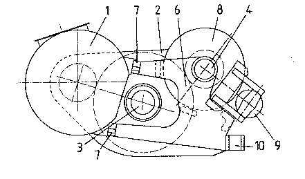
DescIiption of Specif~c Embodiment
The drive motor is denoted as 1 and typically supplies in modern, high capacity
locomotives a cruising capacity of about 1,6 MW. A transmission 2 flange-
connected ~ereto drives on the one hand a hollow shaft 3 which is connected in
5 driving relationship to the wheel set a~is (not illustrated3. At the same time,
however, also on ~hat side which is opposite to the motor 1 of the hollow shaft 3
a power take-off is provided to which a brake shaft 4 is fitted in driving
relationship.
l~e brak~ shaft 4 is now mounted rotatively on the one side at 5 in the casing of
0 the transmission 2 and at the opposite end in the front region 6 of a beam
projecting from the motor 1.
As indicated at 7 by a flange connection, the front portion 6 of the beam is
releasable and removable and thereby also the bealing which is opposite to the
driving connection of the brake shaft to the hollow shaft 3. As a result the
5 brake discs 8 provided on the brake shaft 4, if they are releasably fitted, can be
readily removed res~ectively refitted to the bl~ke shaft 4 or, where appropriate,
the entire brake shaft 4 including the brake discs 8 provided thereon can be
disconnected .
The brake callipers 9 acting onto the brake discs 8, in order to avoid relative
2 o movements, are advantageously likewise fitted to the motor-transmission u~it 1,
2, but can also be fitt~d to the bogey chassis (not illustrated).
: "
Although ~n ~e drawing, by way of example, two brake discs 8 are illustrated,
their maximum number is limite~ in an upward direction only by the length of
the brake shaft 4, whereas, even in the event of a single brake disc only, the
2 s brake capaci~ is clearly increased as compared with conven~onal cons~uc80ns
~ j,.....
,. .. ' ' ' ', ' . ' . ' ' ' . , . .. . " ,' ,' ',"' ', ',,, ' ' ' ' ' ' ' . ', . ~ ,. ' ', , " " ' ' ' " ' .' , . , '
' ' ' ': : ., ' :: .'. ' ' : ' . " ' . , :, ', , , ', .,, .: .. .. . .
- 210~48
of a brake disc due to the mechanically substantially more stable two-sided
mounting of the brake shaft 4.
An additional advantage results with the employment of the illustrated module
in a dual axle power bogey, because due to the reduced distance between the
5 motor 1 and the hollow shaft 3 wi~in which the wheel set axle extends, a bogeycan be attained having a clearly reduced a~le spacing, which due to this short
wheel base provides a clearly improved curve going ability.
The increased space requirement on that side of the hollow shaft 3 which is
opposite to the motor 1 is of no importance, because that space in conventional
0 bogeys is largely unu~lised.
The regions of the casing for the transmission respectively of the front portion 6
of the beam on the side which is opposite to the casing of the transmission 2,
proYided for the accommodation of the bearings of the brake shaft 4 may
advantageously at ~e sarne time be u~lised in conjunction with fitt~ng means 10
15 for components for suspending the motor-~¢ansmission unit 1, 2 together with
the brake installation on the bogey chassis or also on the vehicle chassis.
The claims which follow are to be considered an integral part of the present
disclosure. Reference numbers (directed to the drawings) shown in the claims
serve to facilitate the correlation of integers of the claims with illustrated
2 o features of the prefeIred embodiment(s), but are not intended to restrict in any
way the language of the claims to what is shown in the drawings, unless the
contrary is clearly apparent from ~e context. ~i
. ' . .
.. ., , .; . ;, . . , . ,, - , , , ... . . .. :,
.. . . . . . . . .. . . .
.,,. ~ , " ,; ~ ,, ... , , .. ;.,:
, . , , , . . :