Note : Les descriptions sont présentées dans la langue officielle dans laquelle elles ont été soumises.
~ - 21~7~7~
-1- Docket: 0116-76
ADHESIVE TAPE ROLL
.. A nf th~ Tnv-.ntinn
Fi~1-1 of ~h~ Tnve~
The irlvention relates to an adhesive tape roll, in particular for a
5 clothes cleaning device.
An adhesive tape roll for a clothes cleaning device is known from
German ærrli~stinn DE 31 11 150 C2 in which a single adhesive tape is
wound on a winding mandrel. The adhesive tape consists of a stressed
st~ip coated on only its outside with adhesive. The adhesive tape is
10 provided with separation lines formed by weakened points in the tape at
,t,;hw;i~ distances crosswise to the l~ ;llw;i~c direction
of the tape. The distAgnces between the s~ps Ytin~ lines are equal to one
another. A layer made of an a~hesive-repellir~g material is applied in each
case on the imner side of the tape, a layer that extends in the l~ Slhw;i~
15 direction of the tape to less than two thirds of 1~.5;1.w~c separation of
adjacent separation lines. The separatiorl lines aTe placed in each cæe in
the middle of the adhesive-repelling layer and are made æ lines of
perforations. However, when a used tape section is torn off, fu~z can
remain on the edges between the p~.rv-dlivll~ that adheres to the adhesive
20 layer of the tdpe section Iying under it and makes it more difficult to grasp the unused tape section.
1 2~7~
- 2 - Docket: 0116-76
~llmm~l~y of th~ T~Avention
The primary object of the present invention is to provide an adhesive
tape roll, in particular for a clothes cleaning device, in which the grasping
of a new tape section can be performed in a practically ~ manner.
To achieve this object, an a&esive tape roll for a winding mandrel,
according to the invention, has several separated a&esive tapes, which, in
each case, have a stressed strip made of flexible, ~ material, in
particular paper, an a&esive layer on only the one side of the strip, and
on the other side of the strip, in an end section of the strip extending over
the entire strip width, an adhesive-repelling mate~ial layer. The a&esive
tapes are wound on top of one another, alternately in one and then the
other direction around the winding mandrel, so that the a&esive-free sides
at least of all a&esive tapes wound after the f~rst adhesive tape, face the
winding mandrel, and for each adhesive tape, the adhesive-repelling
material layer lies on the adhesive layer of the same a&esive tape.
With this design, each of the originally separated adhesive tapes can
be grasped at the end section provided with the a&esive-repelling material
layer and can be pulled off the adhesive tape roll without .l . rr;. ~ ,, arising
during the grasping of the adhesive tape, because the exposed end has no
20 fuzz at all and does not adhere to the adhesive layer Iying, \.~AIl. it.
Because the winding ~irection alternates from adhesive tape to adhesive
tape, when an adhesive tape is pulled off, it ig also assured that the
following adhesive tape is not pulled off with it, because the direction in
which the outermost adhesive tape is pulled off ~o l~,~ull ;Is to the winding
direction of the following adhesive tape.
7~7~
- 3 - DoGket: 0116-76
Preferably, the adhesive-repelling material layer of each wound
adhesive tape lies on the adhesive layer at the other end section of the same
adhesive tape. Here, each adhesive tape is smaller than two maximum
wh~,u~l~f~ L~l lengths of the adhesive tape roll and only slightly larger
S than o~e maximum ~ul.lf~ ,.,t;al length of the adhesive tape roll, so that
this adhesive tape roll is especially suited for a clothes deaning device in
which it is sought to minin~ize the extent that each adhesive tape is longer
than the maximum winding c..~u..lf~.~,..~, to use the entire adhesive layer
of each adhesive tape to clean an item of clothing, i.e., not to let the end
10 sectio~s of an adhesive tape overlap too much, to save material.
Then, the overlap area of the end sections of each adhesive tape,
relative to the overlap area of the end section of the previously wound,
adjacemt adhesive tape can be offset in the ~,~...~.~..tial direction of the
winding mandrel. This design has the dvantage that the adhesive tape
roll, despite the overlap of the end sections of each adhesive tape, remains
largely circular, which makes it eæier to clean an item of clothing by
rolling the adhesive tape roll on the item of clothing with the adhesive layer
on the outside.
Further, the end section, having a material layer with no adhesive,
of the adhesive tape wound first, can be turned under on its adhesive-free
side. The turned-under section then adheres to the outside of the winding
mandrel somewhat tightly, so that the first adhesive tape, with its turned-up
section, is fixed on the winding mandrel when the adhesive tape is wound
and does not slip in the Uil~U uf~ direction during winding.
These and further objects, features and adv; ~ of the present
invention will become apparent f~om the following ~l~g~nrtil~n when taken
in c~ with the accc~ g drawings which shows, for purposes
- 4 - Docket: 0116-76
of illllit~thm only, a single ~ ~odi~ in ~Ic~,v~ l~ with the present
invention.
BnPf Descri~tion of the Drawin~c
Figure 1 is a L~~ ,Lv~ view of a clothes cleaning device with
5 adhesive tapes according to the present invention;
Figure 2 is an end view of an a&esive tape }oll according to the
invention, and
Figure 3 is a pc. ~,~,Lv~ view of an adhesive tape according to the
invelntion.
l~pto;lpA DPe~tion of thP Preferred F ~o~
The clothes cleaning device .~ d irl Figure 1 has a slightly
conically tapered handle 1 and a clothes cleaning roll 2 that is mounted to
rotate on an axial extension of handle 1. Clothes cleaning roll 2 has a
hollow ~Lr.dl;~l wir~ding mandrel 3 (see Figure 2) that is made of stiff
15 cardboard. Winding mandrel 3 is provided with an adhesive tape roll 4
which is composed of a plurality of separate adhesive tapes 5, as it is
,l.tcd in Figure 2. An unwound adhesive tape S is 1~ in
Figure 3, in ~ ,liv~;. Winding mandrel 3 is bordered on its ends by
871
- 5 - Docket: 0116-76
disks 6, which are mounted to rotate on the axial extension of handle 1 and
which carry the winding mandrel 3.
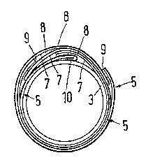
In Figure 2, as an example, only three adhesive tapes 5 are
ll.,~)lC ' 1, although, in practice, a far larger number of adhesiYe tapes 5
S is wound on winding mandrel 3.
As Figures 2 and 3 show, each adh~sive tape 5 comprises a stressed
strip 7 made of a flexible, " ~, material, in particular paper,
preferably crepe paper, which is provided on only one side with an
a&esive layer 8 and, on its opposite side, in an end section extending over
the entire s~ip width, with an adhesive-repelling material layer 9.
Adhesive tapes 5 are wound on winding mandrel 3, one on top of another,
alternately in one direction and then in the opposite direction, so that the
adhesive-free side of strips 7 of at least the second and b"l,~ a&esive
tapes 5, i.e., all but the first-wound adhesive tape 5, face winding mandrel
3 and, for each a&esive tape 5, adhesive-repelling material layer 9 lies on
top of the adhesive layer 8 of the same adhesive tape 5. The area of the
end sections of each adhesive tape 5 is offset in the
cihl,u~llf~ lidl direction of winding mandrel 3 relative to the area of the
uv~ d end sections of the ~Icv;u~.sly woun~, adjacent adhesive tape
5 . End section 10, of f ir6t wound adhesive tape 5, i5 ~olded
under on its adhesive-~ree side so as to bring a portion of
the adhesive side into contact with the winding mandrel 3.
The a&esive-repelling material can involve the use of stearin or
paraffin. Instead of paper, strip 7 can also be made of another material,
25 for example, plastic. Then, the adhesive tapes S can use an adhesive
plaster or other adhesive tapes.
2107~71
- 6 - Docket: 0116-76
To pull off outermost adhesive tape S after, in the case of a clothes
cleaning roll, it is used up, i.e., the outside of adhesive layer 8 is
surLc;~ ly dirty that it will not pick up any more dirt particles, the
outermost adhesive tape S is grasped in its end section that is provided with
S the adhesive-repe11ing material layer 9 and is unwound from a&esive tape
roll 4. The grasping of this end section entails no ~iffl~ , because it
does not a&ere to the other end section of the same adhesive tape 5.
When ullwi~-dillg the outermost adhesive tape 5, the a&esive tape 5 lying
under it is not ~ r-v~ y unwound because the pull exerted on the
10 ' 'y, ' ~;llg adhesive tape 5, when the outermost adhesive tape
5 is pulled off, is directed in the winding direction of the ;~llllf"l 'f' ly
underlying adhesive tape 5.
The turned-under end section 10 prevents the adhesive tape 5 which
is first wound on the winding mandrel 3, from slipping during winding
15 since the turned-under end section 10 a&eres, by adhesive layer 8, to
winding mandrel 3.
It is noted further c.. ~.. r.g Figures 2 and 3, that, for ill~lgtr~tir~n
purposes, the adhesive tapes S have been IG~lGJ~llt~d in a
.li.~u~ ionately enlarged scale, since the individual layers of adhesive
20 tapes 5 cannot be I-~ d on a natural scale.
While various ~1ll1){ " in ~,u..ld~e with the present invention
have beGn shown and described, it is . ~ I..od that the invention is not
limited thereto, and is - -r 1 '- to numGroUs changes and mo-lifir~ti~nc
as known to those sl~lled in the art. Therefore, this invention is not
25 limited to the details shown and described herein, and includes all such
changes and m~lifif ~fionc as are, ~ by the scope of the
appended claims.