Note : Les descriptions sont présentées dans la langue officielle dans laquelle elles ont été soumises.
CA 02108034 2002-08-O1
WO 92/18729 PCT/SE92/00209
Tent and method for p~~tr~l~,na thereg~~
FIELD OF THE INVENTION AND PRIOR ART
The present invention relates to a substantially cone-shaped
tent and a method for pitching such a tent.
Example of this type of tents are huts and tepees and it is of
course a desire to be able to rapidly pitch and disassemble
them, so that it is possible to use them also in occasional
arrangements, such as _itch a camp for one single night or for
any activity for one day or a part thereof.
The invention relates in particular but not exclusively to the
larger so called "giant tent huts", which may have a top height
and base diameter rather often of 7 and 10 metres, respective-
ly. The cone-shaped tents hitherto known of this order of mag-
nitude require too much time to pitch and disassemble in order
to make it reasonable to use them for more occasional or tem-
porary arrangements. First of all it is required to tie the
rods diverging downwardly towards the ground and supporting the
tent cloth at the top so as to interconnect them, which is de-
licate to achieve in an appropriate manner, so that they are
well held together also after the pitching. The rods are tied
together after the very erection, but this. is for natural rea-
sons bothering. Is thereby the conventional technique utilized,
so that the rods cross each other just below the upper end
thereof for obtaining the top bunch characteristic for huts, it
will then be extremely difficult to afterwards get the tent
cloth over the top, should a tent cloth completely sewn up be
used, so that it will be necessary to make the tent cloth cone
brokable by buttons, zipfastener or the like, and this makes
CA 02108034 2002-08-O1
WO 92/18729 PCT/SE92/00209
2
of course the cloth weaker. Also when such a characterizing
bunch or top cross is omitted it will be too difficult to get a
tent cloth with substantially the form of a continuous cone in
place by means of known techniques on huts being so high and
when the tent cloth weight is so considerable that may some-
times be the case. Another disadvantage of the tents of this
kind hitherto known consists in that the means necessary for
interconnecting adjacent rods may not be applied in a
sufficiently rapid and secure way, since 'they generally are
made of cross bars which have to be tied at the respective ends
thereof to the rod in question.
BRIEF DESCRIPTION OF THE INVENTION
'the present invention is directed towards the provision of a
tent and a method for pitching thereat cf the kind mentioned in
the introduction, which enable a more rapid and at the same time
also easier and more secure pitching and disassembling of such a
tent, so that it will be motivated to use even larger such
tents, such as so called "giant tent huts" for temporary
arrangements.
Thanks to the fact that according to a feature of the invention
the means in question adapted to interconnect adjacent rods
~romprise elongated rigid elements with first engaging members
and the tads have second engaging members fitting therewith, it
will accordingly be possible to rapidly and easily after the
erection of the rods interconnect these, so that they occupy
the desired positions defined for supporting and stretching the
~.ent cloth and securely maintain these positions. This leads to
a considerable saving of time and improvement of the accuracy
with respect to the tying method used before.
WO 92/18729 PCflSE92/0~2~9
,. .~a ~s r.~ , .
d ~ \.' ',. ~ , .s ~..
3
According to a second preferred embodiment of the invention the
tent comprises members for pivotally connect the upper end of
each rod to a frame of a support arrangement in the region of
the top of the tent, said frame being intended to be arranged
substantially horizontally and each rod is pivotable substan-
~ially about the horizontal tangent of the frame in connection
points between the rods and the frame when the frame is direr-
ted horizontally. Thanks to these characteristics the rods may
be interconnected when the tent top is located low, preferably
on the ground, and the tent top may thereafter be brought up-
wardly while pivoting. the .lower ends of the rods in the
direction °towards each other until the desired divergence is
obtained. The rods will also in the pitched position be safely
connected to each other through said frame. Thus, in the
definition "connected to each other" or °°interconnected" in the
claims an indirect connection is also comprised such as in this
case obtained by the frame.
According to a further preferred embodiment of the invention
the support arrangement of the tent mentioned above comprises a
support element rigidly connected to said frame, said support
element being arranged under the frame and designed with an
outer circumference arranged to be touch by and support the
resgaective rod extending from the frame and downwardly towards
the ground, when the rods are in the determined mutual position
- for interconnection by means of the rigid elements. This
enables a rapid obtension of the divergence of the rods desi-
red, since a straight line running between the outer periphery
of the frame and the support element forms a gen~ratrix of an
imagined cone created by the inner side of the rods in the
desired pos-ition, and the rods have only to be pivoted so that
they come into abutment on the outside of the support element,
but the support element has above everything also the; advantage
that it owing to the abutment of the rods thereagainst from
difi~erent directions removes every risk for tilting of the
support arrangement and by that improves the stability of the
tent considerably. ,
WO 92/1 ~i729 ' PCf/SE92/~0209
4
Further characteristics being of help for making the pitching
and disassembling of the tent of the type in question more
rational are defined in the other dependent claims and in the
description following hereafter, a particularly advantageous
embodiment of the method according to the invention comprising
features enabling an easy and rapid application of the tent
cloth.
BRIEF DESCRIPTION OF THE DRAWINGS
With reference to the appended drawings, below follows a
specific description of a preferred embod~.m~~xt of the : invention
cited as an example.
In the drawings:
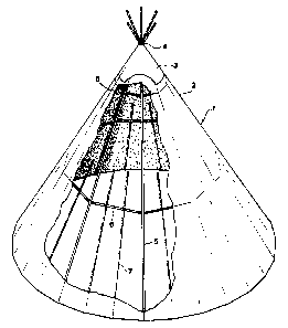
Fig 1 is simplified perspective view of a tent according to the
invention, in which ~ part of the tent clottx has .been broken
away for illustrating the construction of the tent,
Fig 2 is an expioded perspective view illustrating a support
arrangement being a part of the tent according to Fig l: for
holding the rods t~gether in the tog of the tent,
Fig 3 is a side elevation of the supp~rt arrangement according
to Fig 2, which illustrates how the rods are connected thereto,
Fig 4 is a detailed view illustrating how the interconnection
of two adjacent rods takes place in a tent according to Fig 1.
Fig 5 is aside elevation showing a tool applicable in the fop
of the tent according to Fig l for bringing the tent cloth onto
and also pulling the tent cloth off the stand defined by the
rods,
Fig 6 shows in perspective the initial face of an hoisting of a
tent cloth by means of the tool shown in Fig 1, and
VI»192/18729 ~C1'/SE92/~029
Fig 7 shows a view corresponding to Fig 6 in a later phase, in
which the tent cloth has been brought to pass the top of the
stand.
DE ED ESCRZPTZON OF A ERR D EMBODZM NT OF TFi INVENT O
A tent 1 according to the invention of the type °'giant tent
hut'°, which in this case iw the reality is meant to have a
height of about 7 metres and a base diameter of about 1.0,2
metres, as schsmatical.l~r shown in 'Fig 1. The tent 2 has a
' svibst~antial~.y cone=shap~d'~'.t~rit cl'~th r 2 ~ which':-has' an :~~per
::,~;, .~pshing" ~aot vx~s~:ble ' h~~e''for~~discharging~ flue ' gas~~' wheaa
'making
.~ fire . in the tent: Said ~pening 'is in the -~s~.ate'l shown in Fig 1
covered by a flue gas fly or valve 3 which consists of a
substantially cone-shaped cloth hanging from the top 4 of the
tent and which may be hoisted by means not shown or closer
described here for exposing a desired part of said flue gas
Openings
Furthermore; the tent has a stand for supp~rting and stretching
the tent cloth 2, said stand comprising as main components rods
5 connected to each other in the region of the top of the tent
and extending divergingly dc~wnwardly to the ground on which ~.he
tent stand and bear thereagainst each such rod substantially
forming a generatriac of an imagined cone. The rods 5 are
interconnected by elongated rigid elements 6, hereafter celled
cross bars, which in the tent shown are arranged on two diffe°-
rent levels around the tent.,~t will by means of ~'ig 4 later on
be explained how the adjacent rods 5 is coupled to each other
by means of the cross bars 6. Further supporting or carrying
elements 7-~ih the form of long pins are arranged between two
adjacent rods 5 and t~ extend from the ground and upwardly in
the direction of the top of the tent while bearing on the
outside of the cross bars, and they are terminated a little bit
above the lower cross bars.
The construction of the tent according to the invention will
VV~O 92/18729 ~ ~ ~ g ~ ~ (~' ~ . . PGT/5E92/00209
6
now be explained more in detail while describing how the tent
is pitched, a disassembling of the tent being intended to take
place in substantially inverted order of the working moments
should not the contrary be expressed.
Reference is now made to Fig 2 and 3 for explaining the top
construction of the tent. The tent comprises a support
arrangement 8, which is made, of a central tube 9, which is
intended to be arranged so that is extends substantially in
correspondence with the height axis of the tent cone, and rings
~,~ .;~A, ,11 arranged .on different levels around this tube-,,; -which are
:rigidly,. connected.to the tube through three bars 1.2:~ The
.. . .. . :. ,. ., : , , . , :;
surface circumscribed by the respective.ring~is substantially
perpendicular to the extension of the tube 9 and the rings are
concentrically arranged with respect thereto. The upper, first
ring to has a diameter which is smaller than the lower. A
sleeve I3 with a substantially circular top plate-1.4 may be
pushed over the tube 9 and bear on an annular flange 15 on the
tube. The plate 14 is adapted to function as a support flange
for supporting the upper part of the flue gas fly 3 thereon. An
opening 16 is arranged in the centre of the plate 14 for
receiving a pin 17 of a bunch construction 18. The pin 17 is
secured to the underside of the. plate l9, the underside of
which has a shape coanplementary to the upper side of the plate
l~, but spacer members are arranged so as to keep the plates
away from each other for enabling turning of the-flue gas fly.
Six rods 20, preferably of metal, are secured on the upper side
of the plate 19 and bent outwardly-upwardly . The rods 20 are
evenly distributed along the plate 19 and a wood pin 21 hating
a length of about 1 m and with a centre bore for receiving the
respecti.ve.rod 2~ is pushed onto each of the rods. Qnly two
wood pins 22 are shown in Fig 2 for the sake of clearness, but
such pins shall be arranged on all rods 20 yand they,shall be
longer than the both shown in the Figure. Members not shown,
such as strings, are preferably winded around the pins 21 at
the lower end thereof so as to anticipate a formation of cracks
in the pins in the region of the rod bores. The pins,21 are so
WO 92/18729 ~ ~ ~ ~ ~.~°~~ .~ ~., : ' ~'C'T/SE92/00209
7
directed that they in the state applied on the support
arrangement 8 together form a bunch dummy and seem. to
constitute a prolongation of the rods 5, such as in
conventional huts, i.e. the pins 21 constitute prolongations of
the generatrixes of the cone described by the tent cloth. In
this way it is possible to obtain a hut with a traditional
appearance, but' in spite thereof apply a flue gas fly and
easily apply the tent cloth.without being disturbed by the
bunch, since this is applied afterwards.
:;:~ .It is shown in Fi.g 3 how the rods- 5 are intended to be connec-
°ted:.to each other by-an-indirect interc~nnection~'wthrough'~the
-~ support arrangement 8 .The upper ' end - of: the respective rod is
provided with a U-shaped member 22, the two legs of which are
intended to be pushed beyond the first ring l0, so that this is
received in the bottom of the U. Furthermore, the legs of the U
have at the upper ends thereof an opening 23 each for receiving
a locking pin 24 interconnecting the legs, which together with
the legs of the U are arranged to hold the upper end of the rod
in place at the ring 10. The U-shaped member 22 is formed by
securing a flat iron in the rod 5 and bending it in the way
shown in Fig 3. ~y pushing the ends of the .rods onto the ring
10, so that this is received between the legs of the respective
U and after that, introducing the locking pin 24 obliquely from
above, the rods 5 may be rapa.dly and easily connected to the
- support arrangement 8. This connection makes it possible to
piv~t the rods 5 about the tangent of the ring in the connec-
tion point in question. It is at the same time possible to
displace the rods along the rings. The diameter of the second
rang 11 are chosen so that the rods 5 bear on the outside
thereof on..assuming the desired divergence degree from the top
of the tent and downwardly towards the ground. When pitch~:ng
the tent all rods 5 may by that first be applied evenly
distributed around the first ring 10 and the rods after that be
pivoted with their lower ends towards the future centre of the
tent while lifting the support arrangement 8 until they come to
bear against the second ring 11. A possible readjustment may
WO 92/18729 ' Pf.'q'/SE92/00209
take place thereafter. The ring 11 ensures in this way also
that the support arrangement 8 may not tilt, since the rods 5
bear from different directions against the second ring.
After the pivoting just described of the rods 5 to the desired
position the cross bars 6 shown in Fig 1. are applied on two
different levels between the adjacent rods, and how this is
carried out is described more.in detail in Fig 4. The cross bar
6 has at each end a male member 25 directed substantially
perpendicularly to the longitudinal direction of the bar in the
form of an extension:; A loop 26 is arranged , on:;the side .of each
;:~. rod;; intended. >to .face ,; the adjacent :;rod, said.loop :~ defining v
a
female member 27 for receiving an extension 25 of the cross bar
6. The two extensions of the cross bar 6 are preferably direc-
ted parallelly with each other and the loop is arranged with
the female opening thereof directed substantially perpendicu-
larly to the longitud~.nal direction of the rod, so that at
erected rods diverging downwardl:y an introduction of the
extensions 25 therein may take place ~bliquely from above-from
outside and downwardly-inwardly towards the inner ~f the tent
and the gravitation tends by that 'to )seep the cross bar 6 in
place. Thus, the cross bars 6 may be applied at a high fre-
quenCe, since thl~ eXtensl~ns 25 ~nly have to be ptlShed ~nt0 the
loop openings 27 and the interconnnection of adjacent rods 5 is
completed thereafter, in which some small readjustment of the
rods 5 after their pivoting upwardly may be required so as to
make the cross bar 6 to fit therein, and this readjustment is
easily possible thanks to the movable arrangement of the rods 5
in the support arrangement 8. The application of the cross bars
6 will lead to an align~eent of the support arrangement 8, so
that the tube 9 points towards the centre of the base of the
tent, and it may after that not levee this aligned position
thanks to the abutment of the rods 5 therearound.
The moments of the pitching of the tent so far described may be
carried out in a comparatively short period of time, and the
CA 02108034 2002-08-O1
WU 92/18729 PCT/SE92/00209
9
thing now remaining is substantially only to bring the tent
cloth in place, and this is preferably carried out by means of
a cloth hoist tool 28 illustrated in Fig 5, Which may be
applied on the top of the support arrangement 8 before lifting
it by pivoting the rods 5. The cloth hoist or elevating tool 28
consists of a double-armed lever with a first 29 and a second
30 arm, which is pivotably arranged at a post 31, which is de-
signed to fit in the tube 9 of the support arrangement through
the opening 16. A diverting member 32 in the form of a wheel is
arranged at the outer end of the second arm 30 and designed to
divert a traction element 33 in the farm of a cord or line
running thereon. This line 33 is on one side of the substan-
tially cone-shaped tent cloth led from the upper end of the
tent cloth and downwardly to the lower end. thereof in guide
members, preferably a channel sewn on the tent cloth or straps,
wherein members are arranged to prevent the line from leaving
the upper end of the tenth cloth and these members could be
formed by the fact that the line is simply secured to said end.
When starting to bring the tent cloth in plar_e the first arm 29
of the tool 28 is first of all secured in the position shown in
Fig 5 by connecting an eye arranged close to the outer end
thereof with one of the rods 5 through for example a belt. The
line part leaving the lower end of the tent cloth is after that
brought around the diverting whee;L 32 and downwardly towards the
ground. It should be pointed out that these movements of the
hand may take place before the support arrangement 8 is lifted
by pivoting the rods 5. The line 33 is after that pulled in the
direction of the arrow pointing downwardly in Fig 5, by which
the line will catch the lower end cf the tent cloth by the
upper end of the tent cloth thanks to the guide members and in
this way pull the tent cloth folded together on the outside of
the stand towards the tool 28 (see Fig 6~, said pulling being
continued until substantially the entire tent cloth part folded
together has been hoisted and bears on ths: tool 28. A person
climbs after that on a ladder or the like up to the region cf
the tent top and secures the cloth porticn folded together by
means of a belt or the like to the outer eyes of the tool,
WO 92/x8729 ~ : ' ' Pt'Jf/SE92/00209, .
whereupon he releases the first arm 29 from the rod 5 and
pivots the tool so that the second arm 30 will point down-
wardly. Said cloth portion is after that loosened from the tool
and it may now slide downwardly on the side of the tent top
laying directly opposite to the side it was hoisted on. This
position is shown in Fig 7. The tent cloth may after that be
slightly pulled so that it through the gravitation slides down
in place around the rods 5. The carrying elements 7 see Fig 1)
may be applied and possible tent pins may be draven into the
ground at the lower end of the tent cloth when this has been
w~ done': A person may-: after that.r; through .: a .; ;ladder or the like
°'r~v'climb up-sand remove they tool 28 and., apply the , flue gas fly
~ 3
.'and after that a bunch dummy 18:
Disassembling of the tent is preferably started by climbing up
to the top, removing the bunch dummy 18 and the flue gas fly 3
and applying the tool 28 in tire position shown in Fig 5,
whereupon the line 33 is led around the diverting wheel 32; but
now with the line part leaving the upper end ~f the tent cloth,
so-that the lower end o~ tie tent, cloth will be displaced
upwardly towards the tool under folding the tent cloth portion
in question together. Tilting of the tool and sliding down-
wardly of the tent cloth takes place after that in a way
corresponding to what has been described in c~nnection with the
pitching of the tent. Each end of the line 33 has preferably a
member with a greater cross s~cti~n than the guide memdbers of
the tent cloth so as to obtain said function, so that one and
the same line may be used for pitching as well as for discs-
sembling.
It appears...from above that the tent according to the invention
by mexns of the pitching method according to the invention well
may be used f~r temporary arrangements, even in the case of a
so called "giant tent hut°° which may take more than 50 persons,
since the time c~nsumption for pitching and disassembling is
comparatively small.
WO 92/18729 ~ ~ ~ ~ ~ ~~; ' , PCT/SE92100209
1.1,.
The invention is oy course not in any way restricted to the
preferred embodiment described above, but several possibilities
to modifications thereof would be apparent to a man skilled in
the art without departing from the scope of the invention.
It would for example be possible to have another number of
rods, carrying elements and cross bars than shown by the
drawings.
The male and female members arranged on the crossbars and. the
rods, respectively; ,:.:; cold :-of,> :course ;:~be ~: replaced by~.~female.
and
male members, respectively, and be designed in other ways, s~
far as they' form members being.: able to , enter -into .. engagement
with each other. For example the rigid elements could for
example be of the type varying their length in a telescopically
or screwably way and'arxanged to ;bring tha first and second
engaging members into and out of their mutual engagement,
respectively, by modifying the lengi~h of the rigid elemQnts.
The two rings of the support arrangement could be. replaced by
frames with another shape than circu3.ar, the definition "frame"
in the claims relating to the fact that it is h question of any
endless member extending around and surrounding' a greater
opening therein; so that it is possible to completely grip
around parts of the frame as the ends of the rods do in the
embodiment described: The lower support ring could of course be
'constituted by a continuous plate or the like. ~t would also be
possible to provide the ring f0 with members'for making it
impossible to displace the rods attached thereto therealong and
by that exactly defining the connecting points of the rods.
The bunch dummy could of course be omitted when desired, but it
certainly confer a more attractive appearance to the tent
according to the invention.