Note : Les descriptions sont présentées dans la langue officielle dans laquelle elles ont été soumises.
- WO92/l~g6 PCr/US92/0~K9
,;
j
2108136
~u~,lNG A88EMBLY
FIELD OF THE Ihv~NllON
The present invention relates to the cutting of
vegetables, and in its preferred P~hoA; ment to a novel
tool for cutting potatoes into a plurality of helical
strips.
BACKGROUND OF THE lNV ~:N~l loN
Raw potatoes and other vegetables have long been
cut into various sized pieces for cooking or processing by
a variety of methods and machines. Early examples
include, U.S. Patent Nos. 97,047, issued November 23, 1869
to Chrysler (device for cutting vegetables into narrow
strips or slices); 101,520, issued April 5, 1870 to Schaub
(improvement in cabbage cutter); 497,675, issued May 16,
1983 to Miller (fruit or vegetable cutter); 1,534,078,
issued April 21, 1985 to Ruffner (vegetable slicing
machine); and 2,017,559, issued October 15, 1935 to
Wolfinger (beet slicer).
A number of cutting tools and methods are also
known for slicing or otherwise cutting potatoes. See,
e.g., U.S. Patent Nos. 2,464,9g3, issued March 22, 1949 to
Ross; 2,610,664, issued September 16, 1952 to Thompson;
3,057,386, issued October 9, 1962 to Massaro; 3,217,768,
issued November 16, 1965 to Lamb; 3,952,621, issued April
27, 1976 to Chambos; and 4,387,111, issued June 7, 1983 to
Mullender.
One known method of cutting potatoes into a
plura~ ty of helical strips involves rotating a potato
against a fixed blade cutter. The device includes a
cutting plate having a pivot pin for engaging one end of 2
WO 92/18296 ` . PCI`/US92/02869
- 2 _ 2 1 08 1 3 6
potato. The other end of the potato is engaged by a
toothed drive disk which is mounted opposite the plate on
a crànk driven shaft. A set of slitting knives protrude
from the surface of the cutting plate and a cutting knife
is mounted to the cutting plate adjacent the pivot pin.
The blade of this knife extends radially from the pivot
pin in a plane parallel to the surface of the cutting
plate. These knives cut the potato into a plurality of
helical strips as it is rotated against the cutting plate.
Although this device produces helically-cut
potato strips, it suffers from several problems. First,
since the potato is rotated against the cutting plate, a
center core of the potato is progressively crushed against
the plate resulting in waste and degradation of the
product. The toothed drive disk also causes further waste
since the potato cannot be cut into helical strips from
end to end without interference between the teeth of the
drive disk and the cutting knives. The speed of operation
of this device is further limited by the time required to
load a potato into axial alignment with the pivot pin and
drive disk and by the limitations on rotational speed of
the crank.
Further discussion of the history and operation
of such cutting devices can be found in U.S. Patent No.
4,644,838 entitled "Apparatus for Helical Cutting of
Potatoes", issued to Samson et al. on February 24, 1987
and assigned to Rogers Walla-Walla, Inc. (hereinafter the
'838 patent). That patent discloses a method and
apparatus for cutting articles such as potatoes into
helical strips wherein the potato is held against rotation
and aligned by a plurality of fingers and moved
longitudinally against a rapidly rotating cutting head.
The particular cutter head disclosed in the '838
patent included a plurality of slitting knives which
extend outward in a generally parallel alignment with the
axis of rotation of the cutter head. The knives were
positioned to form concentric longitudinal cuts in the
potato. Helical strips are produced by a transverse
blade, the cutting edge of which protrudes from the face
WO92/18296 PCT/US92/0~9
` - 3 - 2108136
of the cutter head as the cutter head is rotated against
the potato. The cutter head may include a center pin for
engaging the potato or, alternatively, could have included
an upstA~ing cutting tube mounted at the rotational
center of the cutting head. That tube is sharpened and
- cuts a cylinder of material from the center of the potato.
While operation of the cutting device of the
'838 patent overcame many of the difficulties of prior art
cutting devices and provided a method for rapidly cutting
a potato into a plurality of helical strips without waste
of a significant portion of the potato, there remains a
need for a cutting head which would improve the efficiency
of the cut. Moreover, while various cutting heads are
known, such as those shown to be useful in food processors
and the like (see, U.S. Patent Nos. 4,393,737, issued July
19, 1983 to Shibata and 4,228,963, issued October 21, 1980
to Yamauchi), or those shown in the patents cited above,
such known cutting heads fail to fully address the
foregoing deficiencies.
SUMMARY OF THE INVENTION
The present invention features a tiered, cone-
shaped blade which is useful in a variety of applications,
such as for automatically cutting vegetables, such as
potatoes, into elongated helical strips. The present
invention, in its preferred embodiment, comprises a
cutting assembly having a plurality of blades arranged in
tiers. The blades are positioned to form concentric
longitudinal cuts in the potato, such that helical strips
are produced in an efficient and reproducible manner.
How the present invention provides these
benefits will become apparent shortly as the preferred
embodiment thereof is described in connection with the
drawings. Generally, however, the benefits are provided
by mounting a cutting assembly in an apparatus for helical
cutting of potatoes. The cutting assembly may be utilized
in the same manner as conventional cutter heads. When so
used, improved cutting efficiency is obtained.
W092/182~o ~ PCT/USg2/02~9
~ - 4 ~ 2 1 0 8 1 3 6
Other ways in which the benefits of the present
invention can be embodied and modified by those skilled in
the art for a variety of applications will be discussed in
the following sections of this specification.
BRIEF DESCRIPTION OF THE DRAWINGS
A preferred exemplary embodiment of the present
invention will hereinafter be described in conjunction
with the appended drawings,-wherein like designations
denote like elements. Furthermore, scale is not employed
in the drawings and some components of a typical cutting
apparatus have been eliminated for purposes of showing
with greater clarity those components which pertain to the
present invention.
Figure 1 is a perspective view of a cutting
apparatus with which the cutting assembly according to the
present invention may be employed;
Figure 2 is an exploded perspective view of the
f ~in~, holding and cutting mechAnicms of the cutting
apparatus of Figure 1 with parts broken away;
Figure 3 is a top plan view of the cutting
apparatus of Figure 1 with parts broken away;
Figure 4 is a perspective view of the cutting
assembly according to the present invention; and
Figure 5 is a cross-sectional view of the
cutting assembly according to the present invention taken
along line 5-5 of Figure 4.
DESCRIPTION OF THE PREFERRED EMBODIMENT
The present invention will be described in this
section of the specification as part of a cutting
apparatus, but it should be appreciated that the novel
features of the invention make the invention particularly
suitable for use in many other types of devices and
apparatus such as, but not limited to, machines for
slicing, cutting or otherwise processing vegetables or
other food stuffs, where the object to be cut is held
against rotation and moved into engagement with a rotating
cutting assembly.
WOg2/182~ PCT/US92/0~9 -
~ ~ 5 ~ 2108136
Before proc~e~ing to a more de~ailed description
of the preferred embodiment, it will be helpful to point
out the basic elements of the present invention as
incorporated in a cutting apparatus such as the one
disclosed in the '838 patent. For this purpose, reference
should first be made to the schematic diagrams shown in
Figures 1 and 2, depicting a cutting apparatus 10. It
should be understood at the outset, however, that the
cutting apparatus could be widely varied and that the
potato f~e~ing and other components of the '838 patent
could be changed without departing from the scope of this
invention. The cutting assembly described in detail later
could be used with any cutting apparatus in which the
object is held against rotation and forced through a
rotating cutting head.
As best shown in Figure 1, this apparatus
includes a frame 11 to which is mounted a rotatable feed
mechA~i-cm 12 driven by an ;n~eying mechAni-~m 13. A
plunger merhAnism 14 and a cutting mechanism 16 are
positioned about the periphery of apparatus 10. A
vibrating conveyor 17 transports potatoes to an annular
supply tray 18 rotatably mounted to frame 11.
As shown in Figure 1, feed merhAni~m 12 includes
a feed table 19 mounted on a rotatable vertical shaft 21.
Feed table 19 is of generally circular configuration and
includes a plurality of open-bottomed feed cups 22 mounted
in apertures about its periphery. The open lower ends of
cups 22 are positioned immediately above an annular
support plate 23 which is mounted to frame 11 and
supported above the surface of a lower table 24 by a
plurality of support legs 26.
As best illustrated in Figure 2, a strip 27 of
low friction plastic material is positioned beneath cups
22 and mounted to support plate 23 by a plurality of
screws 28. A plurality of apertures 30 are suitably
provided in support plate 23 and strip 27 such that the
potatoes to be cut can be loaded into cutting system 16.
Referring again to Figures 1 and 3, indexing
mechanism 13 is operated by a pneumatic drive cylinder 29
WO92/182g6 ~ ~ PCT/US92/O~Kg
~ 6 - 21 08136
and a pneumatic locking cylinder 31. One end of drive
cylinder 29 is mounted to frame 11 and the other is
attached to the free end of a ratchet arm 32. The other
end of ratchet arm 32 is pivotally mounted to shaft 21. A
pawl 33 is pivotally mounted to ratchet arm 32 adjacent
the attachment point of drive cylinder 29 and is spring
biased into engagement with a ratchet wheel 36 which is,
in turn, mounted on the shaft 21. A pair of limit
switches 34, 35 are positioned, respectively, to close
when cylinder 29 is in its fully retracted and extended
positions. Extension of drive cylinder 29 thus results in
rotation of arm 32, pawl 33, ratchet wheel 35 and drive
shaft 21. Since feed table 24 is also attached to drive
shaft 21, operation of drive cylinder 29 results in
rotation of feed table 24. The length of arm 32 and
stroke of cylinder 29 are chosen such that operation of
cylinder 29 sufficiently moves table 24 to position the
next set of cups 22 above the apertures 30 in support
plate 23.
With continued reference to-Figure 1, plunger
merh~ni~cm 14 comprises four identical plunger units 42.
Each plunger unit 42 includes a double acting pneumatic
cylinder 43 mounted to frame 11, such as by upper and
lower brackets 44, 46. Plunger head 47 is mounted on the
shaft of pneumatic cylinder 43. A rod 48 is mounted to
plunger head 47 and is slidably supported by lower bracket
46 for vertical movement with plunger head 47. Upper and
lower limit switches 49, 51 are mounted, respectively, on
upper and lower brackets 44, 46 in position for actuation
by a tab 52 mounted on the free end of rod 48,
respectively, when pneumatic cylinder 43 is fully
retracted or extended.
Referring more particularly to Figure 2, plunger
head 47 is formed with a plurality of grooves 53 extending
longitudinally-along the sides of plunger head 47.
Grooves 53 cooperate with elements of cutting mechanism
16, as described below, to provide complete and accurate
cutting of potatoes or other vegetables.
WO92/182~ PCT/US92/O~K9
-
~ 7 ~ 2108136
Cutting me~hAnism 16 preferably comprises four
identical cutting units 56. As best shown in Figures 1
and 2, cutting units 56 include a holder 57, a rotatable
cutting assembly 58, a support 59 for rotatably mounting
the cutting mech~n;cm to the table 24, and a drive unit 61
for rotatably driving cutting assembly 58.
Holder 57 receives and aligns potatoes for
cutting and secures the potatoes against rotation during
the cutting process. Referring more particularly to
Figure 2, holder 57 includes a tubular body 62 for
receiving potatoes and is mounted on a base plate 71. A
plurality of fingers 63 are hinged to body 62 adjacent the
upper lip of body 62 and extend into body 62 through
corresponding slots 64. The inner surface 66 of each
finger 63 is blunt to prevent cutting of the potatoes held
in body 62. In accordance with the illustrated embodiment
of the invention, six fingers 63 are hinged to body 62.
A pin 68 is pivotally connected to each finger
63. Preferably, six pins corresponding to each of the six
fingers 63 are employed. Each pin 68 extends through a
corresponding slot 72 in a ring 69 and includes a head 73
which bears against the outer surface of ring 69 to limit
inward travel of finger 63. A spring 67 is positioned
about each pin 68 for independently biasing each
corresponding finger 63 into the interior of body 62. The
outer end of springs 67 bear against ring 69. Ring 69 is
not mounted on base plate 71, but rather is free to float
as each finger 63 moves upon positioning of a potato in
holder 57, thus allowing holder 57 to accommodate and
align even highly irregularly shaped potatoes within body
62.
As shown best in Figure 2, a pair of nozzles 65
are mounted on base plate 71 for supplying rinse water to
cutting assembly 58. Preferably, holder 57 is constructed
such that ring 69 is mounted in a groove (not shown) in
base plate 71, and a plurality of drain holes 75 are
provided in base plate 71. In this manner, rinse water
supplied to cutting assembly 58 is readily drained away.
WO92/182g6 PCT/US92/0~69
~ 8 - 21 081 36
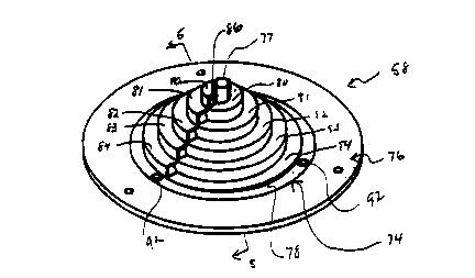
As shown in Figures 2 and 4, cutting assembly 58
preferably includes a blade assembly 74 and a flanged
mounting plate 76. A plurality of mounting holes 75 are
provided about the periphery of plate 76 which correspond
to a like plurality of mounting holes (not shown) on the
cutter drive assembly 61 to receiver mounting means such
as flush screws. Alternatively, the outer flange 95 of
the mounting plate 76 may be threaded for mounting on the
cutter drive assembly 61.
As shown best in Figures 4 and 5, blade assembly
74 has a generally spiroidal configuration. Blade
assembly 74 includes a central cutting tube 77, a base
plate 78 and a plurality of cutting tiers helically
disposed therebetween. Preferably, blade assembly 74
comprises one or more tiers, and more preferably two or
more tiers. In accordance with a preferred embodiment,
five tiers 80, 81, 82, 83 and 84 form blade assembly 74.
In accordance with the preferred embodiment of the present
invention, each tier 80-84 is helically disposed about
central cutting tube 77.
Each tier of blade assembly 74 includes at least
one open cutting end 86. For example, as shown in Figures
4 and 5, tier 80 includes an open cutting end 86. Each
tier also includes three walls. For example, tier 80
includes an inner side wall 87, an outer side wall 88 and
a generally planar but inclined top wall 89. In
accordance with a preferred embodiment of the invention,
the open cutting ends of each tier are aligned with the
cutting ends of the other tiers as illustrated best in
Figure 4.
With continued reference to Figures 4 and 5,
tier 80 is helically wound downwardly about cutting tube
77 such that top wall 89 is below top 91 of tier 81.
Preferably, the top walls of each of tiers 80-84 falls
approximately 0.25 inches per 360 revolution (depending
on the cross-sectional size of the desired final product).
In this manner, when cutting assembly 58 including blade
assembly 74 is used to cut potatoes or other vegetables,
helical strips are formed and cut by each tier 80-84. The
` WO92/182~ ~ PCT/US92/0~9
-
- 9 - 2 1 08 ~ 36
downward slope of each tier 80-84 causes the helically-cut
strips of potato or other vegetable to pass through the
interior of blade assembly 74 and be collected as
- hereinafter described.
Preferably, tiers 80-84 have a width of from
about 0.2 to about 0.4 inches. More preferably for a
helical potato of about 0.25 inch cross section, the width
of tiers 80-84 is in the range of from about 0.23 to about
0.28 inches, and most preferably about 0.2750 inches. The
height of each tier 80-84 is preferably in the range of
about 0.2 to about 0.4 inches, and is most preferably
about 0.250 inches for a 0.25 inch product. As noted
above, the top wall of each tier, and thus the tier
itself, is angularly aligned with respect to base plate 78
such that each tier rises about 0.250 inch over the
helical path about central tube 77. It should be
appreciated that these dimensions are illustrative for a
helically cut potato strip having a cross-section of about
0.25 inch. These dimensions therefore may be
appropriately increased or decreased, as desired, for
resulting larger or smaller cross-section strips of
helically cut potato.
Central cutting tube 77 is positioned interiorly
of tiers 80-84 and is fixedly attached to tier 80.
2S Preferably, the upper surface of tube 77 extends upward
from top wall 89 of tier 80 to a position approximately
0.125 inch above top wall 89. Cutting tube 77 of blade
assembly 74 may be cut off at an angle (not shown), and is
sharpened about its periphery so that it not only
penetrates the potato but actually cuts a cylindrical core
from the center of the potato, the core being preferably
in the range of about 0.3 to about 0.35 inch, and most
preferably about 0.313 inch. In commercial use, this core
should be quite small since it usually is separated from
the helical cuts prior to further processing.
Cutting tube 77 is oriented such that the
lowermost end of tube 77 extends below the top wall of the
second horizontal tier blade 81. As such, breakage of the
innermost helical strip cut by blade assembly 74 is
WOg2/182~ ~ PCT/US92/02869
O- 2108136
minimized, since this strip has a radius approximately
equal to the radius of the cutting tube 77. The presence
of tube 77 tends to minimize damage and breakage of the
spiral strips of potatoes as they are cut and eliminates
crushing of any portion of the potato against the surface
of the blade assembly 74.
The cutting portion of assembly 74 preferably
has an overall diameter in the range of about 2.S to about
3.5 inches, and most preferably about 3.0 inches. In this
manner, even large potatoes can be easily cut into helical
strips. For potatoes, or other vegetables that are
smaller than the diameter of the cutting portion of blade
assembly 74, only the uppermost tiers, e.g., tiers 80 and
81, would be used to cut the potato into helical strips.
Base plate 78 of blade assembly 74 includes a
plurality of mounting holes 92 about its periphery which
correspond to a plurality of holes 93 in the recessed
interior flange 94 of mounting plate 76. Flush mounting
screws (not shown) preferably are used to secure blade
assembly 74 to mounting plate 76 and do not project from
either the upper or lower surface of the cutting assembly
58.
Breakage of the helically-cut strips of
vegetable is also reduced by the shape of the tier blades
80-84. The open ends of these blades extend vertically
from the blade assembly 74 and travel in a circular path
as the blade assembly is rotated. Preferably, the radius
of curvature of each tier blade is approximately equal to
the radius of the circular path traveled by such blade,
advantageously reducing the tendency of the helical strips
of potato to break during cutting and handling.
Additionally, the downward inclination of each tier,
described above, tends to force the helically-cut strips
downward through apparatus 10 further preventing breakage.
Blade assembly 74 is preferably made by
machining a stainless steel preform, and thereafter,
cutting tube 77 is drilled such that open top and bottom
ends are obtained.
WO g2/182g6 PCr/USg2/02869
- 2 1 0 8 1 3 6
With reference to Figure 2, cutter drive
assembly 61 includes a drive tube 9 which is rotatably
supported in the cutter support housing 59 by upper and
lower ball bearings (not shown). The upper end of drive
tube 96 is threaded to receive cutting assembly 58 and a
seal 9 is positioned between support housing 59 and drive
tube 86 to seal out water from the nozzles 65. Drive tube
9 is preferably driven by an electric motor and pulley
arrangement, known to those skilled in the art. Cutter
housing 59 and holder 57 are both mounted to table 24.
Spray shield 102 is mounted to frame 11 and
encircles the lower end of drive tube 96. A tubular chute
100 is mounted to spray shield 102 and extends upwardly
into drive tu~e 96 to a position just beneath cutting
assembly 58. Chute 96 conducts the helically-cut potato
strips and rinse water away from cutting assembly 58, and
prevents contact between the helically-cut potato strips
and the rotating drive tube which otherwise could result
in the strips being held against the walls of the tube by
centrifugal force. Any water which leaks between drive
tu~e 96 and chute 100 drains to the bottom of drive tube
96 and is caught by spray shield 102 and drains out
through holes 104 in the bottom of shield 102. The
helically-cut potato strips may be collected in hoppers
(not shown) located proximate apparatus 10.
In operation, potatoes are transported to
annular conveyor 18 by a vibrating conveyor 19. Workers
are positioned about the periphery of the machine to take
potatoes from conveyor 18 and insert them into cups 22
mounted on feed table 19. Alternatively, the loading of
potatoes into feed caps 22 may be automated, as is known
in the art and is described in the '838 patent. Apparatus
- 10 is then activated. Pneumatic cylinders 43, originally
in their retracted position, once energized, are extended,
causing plunger head 47 to extend and push a potato from
cup 22 into holder 57. Fingers 63 and holder 57 are
pushed outward as potatoes enter tubular body 62 and grip
the potatoes by their sides, aligning them vertically and
holding them against rotation.
WO92/182~ PCT/US92/0~9
~ 12 - 2 1 0 8 1 3 6
The downward stroke of cylinders 43 force the
potatoes into contact with rotating cutting assemblies 58.
The novel blade assembly 74 of the present invention then
cuts the potato into helical strips. The cutting
cont;n~ until cutting tube 77 reaches plunger head 47.
As plunger head 47 moves downward through holder 57,
vertical grooves 53 in plunger head 47 receive fingers 63.
Grooves 53 are of a sufficient depth to avoid interference
with finger 63, which must continue to hold the potato
against rotation throughout the entire downward stroke of
cylinder 43. As tier blades 80-84 cut the potato into
helical strips, a cylindrical core is also cut also from
the potato by cutting tube 77.
The operation of cutting apparatus 10 may be
advantageously monitored and controlled by a conventional
programmable controller, such as is discussed in the '838
patent. It will be understood that the above description
is of a preferred exemplary embodiment of the invention,
and that the lnvention is not limited to the specific
forms shown. For example, different numbers of tiers may
be used to form the blade assembly. Moreover, the blade
assembly is useful in cutting apparatus distinct from that
shown herein, as is known or is hereafter devised by those
of ordinary skill in the art. Various other
substitutions, modifications, changes and omissions may be
made in the design and arrangement of the elements of the
invention without departing from the scope of the
invention as expressed in the appended claims.