Note : Les descriptions sont présentées dans la langue officielle dans laquelle elles ont été soumises.
~;~';g','' ';
rw~;:~
- 1 -
DOWNHOLE TOOL
BACKGROUND OF THE INVENTrON
The invention relates to a downhole tool such as a
well-logging tool, and more particularly to a tool of the
measure-while-drilling (MWD) type.
When oil wells or other.boreholes are being
drilled it is frequently necessary to.detexmirte the
orientation of. the drilling tool so that it can be steered
in the correct direction. Additionally, information may be
required concerning the nature of the.strata being drilled,
or the temperature or pressure at the base of the borehole,
for example. There is thus a need for measurements of
drilling parameters, taken at the base of the borehole, to
be transmitted to the surface.
One method of obtaining at the surface the data
taken at the bottom of the borehole is to withdraw the drill
string from the hole, and to lower measuxxng instrumentation
including an electronic memory system down the hole. The
relevant information is encoded in the memory to be read
when the instrumentation is raised to the surface. Among
the disadvantages of this method are the considerable time,
.' effort and expense involved in.withdrawing and replacing the
drill string. Furthermore, updated information on the
drilling parameters is not available while drilling is in
progress.
A much-favoured alternative is to use a measure-
while-drilling tool, wherein sensors or transducers
~.r ~ ~ :.; a :::~ ~
~i .,Z il t~ SJ
positioned at the 7,ower end of the drill string continuously
or intermittently mpnitor predetermj,ned drilling parameters
and the tool transmits the appropriate information to a
surface detector while drilling is in progress. Typically,
such MWD tools are positioned in a cylindrical drill collar
close to the drill bit, and use a system of telemetry in
which the information is transmitted to the surface detector
in the form of pressure pulses through the drilling mud or
fluid which is circulated under pressure through the drill
string during drilling operations. Digital information is
transmitted by suitably timing the pressure pulses. The
information is received and decoded' by a pressure transducer
and computer at the surface. -
The drilling mud or fluid is used to cool the
drill bit;, to carry chippings from the base of the bore to
the surface and to balance the pressure in the rock
foxmations_ Drilling fluid is pumped at high pressure down
the centre of the drill pipe and through nozzles in the
drill bit. It returns to the surface via the annulus
between the exterior of the drill pipe and the wall of the
borehole.
In a number of known MWD tools, a negative
pressure pulse is created in the fluid by temporarily
opening a valve in the drill collar to partially bypass the
flow through the bit, the open valve allowing direct
communication between the high pressure fluid inside the
drill string and the fluid at lower pressure returning to
the surface via the exterior of the string. However, the
high pressure fluid can cause serious wear on the valve, and
often pulse rates of only up tv about 1 pulse per second
have been achieved by this method. Alternatively, a
positive pressure pulse can be created by temporarily
restricting the flow through the downpath within the drill
String try partially blocking the downpath.
US-A-4914637 (positec Drilling Controls Ltd)
discloses a number of embodiments of MWp tool having ~z
! ...1 :1 ~.~ ~.o
) I ,,
!J~_.I_.~:1 1U
__ 3 _.
pressure modulator for generating positive pressure pulses.
The tool has a number of blades equally spaced about a
Central body, the blades being split in a plane normal to
the longitudinal arts of the body to provide a set of
stationary half-blades, and a set of rotary half-blades. A
temporary restriction in the fluid flow is caused by
allowing the rotary half-blades to rotate through a limited
angle, so that they are out ox alignment with the stationary
half-blades, the rotation be~.ng controlled by a solenoid-
actuated latching means. In one embodiment, the drilling
fluid is directed through angled vanes in front of the split
blades in order to impart continuous torque to the rotary
half-blades, such that the rotary half-blades rotate through
a predetermined angle in the same direction each time the
latch is~released, thus being rotated successively into and
out of alignment with the stationary half-blades.
The provision of angled driving vanes or blades
upstream of the pulse--generating rotary half-blades is a
generally convenient way of providing the necessary torque
to the rotary half-blades to enable them to rotate and thus
generate the pusses. we have tound, however, that this
arrangement can give rise to certain problems. In
particular, as the flow of drilling fluid acts on the
driving blades to provide the required driving force, an
equal and opposite force is exerted on the fluid Which, as a
result, develops a swirling motion.' The swirling rnotion of
the fluid then tends to impair the operation of the
downstream pulse-generating half-blades. In particular, the
swirl of the fluid acts on the half-blades in the direction
opposite to that in which the half-blades are being driven
to generate the pressure pulses. clearly, this may impede
or even prevent the movement of the half blades, and thus
the generation of the pulses.
~UMMARSf OF THE I~iVEN'~ION
In accordance with the present invention, the
r.'~ e~ :~ ') ;~ (~
- q , ~~L~~:7e1.)~
problem described abpve is reduced or overcome by providing,
upstream of the pulse-generating half-blades, means for
substantially cancelling out or removing the swirling motion
of the fluid so that the fluid has a generally straight even
flow as it encounters the pulse-generating half-blades.
According to the present invention there is
provided a downhole tool for generating pressure pulses in a
drilling fluid, the tool comprising an elongate body for
positioning in a drill collar of a drill string; a plurality
of blades spaced around the body, each blade being divided
into an independent front section and rear section, forming
a set of front sections and a set of rear sections, at least
one of the set of front sections and the set of rear
sections being mounted for rotation and being angularly
displaceable relative to one another between a first
position in which the sections are-aligned arid a second
position in which the rear blade sections obstruct the fluid
flow between the front sections to generate a pressure
pulse; a first set of driving blades in front of the
plurality of blades for generating a torque on the front
sectipns, the driving blades being curved in a first
direction; and escapement means to permit stepwise rotation
of the blade sections between said First and second
positions; characterised in that the tool additionally
comprises means positioned in front o~ the set o~ front
sections whereby the fluid has very little, if any, swirling
motion as it reaches the said set of front sections.
in a preferred e~odiment, said means comprises at
least one stator blade, usually a set of stator blades,
positioned in front of the set of front sections the stator
blades being curved in a second direction opposite to said
first direction. Thus, swirl in a first direction is
imparted to the fluid by the stator blades and swirl in the
opposite direction is imparted to the fluid by the first set
of driving blades, such that the swirling motions
substantially cancel each other out and the fluid passes
J
- r~ ..
through the pulse--generating half.-blades with very little,
if any, swirl.
In a preferred embodiment the first set of driving
blades are positioned iri frorit of the set of front sections,
and the stator blades axe positioned in front of the first
set of driving blades.
In US-A-4914637, the rotary half-blades always
move in the same direction With respect to the stationary
half-blades. As a result, a scissor action occurs between
the leading edge of the rotary half-blades and the trailing
edge of the stationary half-blades at the interface between
the half blades, as the rotary half-blades move from the
position where they are out of alignment with the stationary
half-blades to the aligned position of the next stationary
half blade. Thus, any debris or other foreign matter which
finds its way into the drilling mud, may be caught at the
interface of the blades as this scissor action occurs and
thus jam the whole tool, or cause considerable damage to the
blades.
Our capending British patent application no.
9120854_6 aims to overcome this disadvantage, by providing a
means of moving either one or bath of the~front and rear
sets of half blades such that each successive incremental
rotation of one set of half-blades relative to the other set
of half-blades occurs in the opposite direction to the
previous incremental rotation relative to the other set of
half-blades.
In the illustrated embodiment of copending British
patent application no. 9120854.6, both sets of half-blades
are mounted for rotation such that said rear half-blades are
rotatable in one direction from the first to the second
position, and said front half-blades are subsequently
rotatable in said one direction from said Second to said
first position. The half-blades are mounted on a rotatable
member arid the torque is developed by means of the front and
rear half-blades, which are curved to act as lifting
sections.
a q ~i~ ~y~ :y~
6 - ~,~~t~elt.l~
The axxarigemerit of the present invention is
equally applicable to the SGissor-type arrangement of US-A-
4914637 and to the non-scissor arrangement of our British
patent application nv. 91Z0854-b. In the latter case,
the first set of driving blades generates a tai:c~ue--opt the
front sections and a seCOrid set of driving blades is also
provided for generating a torque on the rear sections, the
driving blades preferably being ourved Xn the first
direction, and preferably being placed at the rear of the
set of rear sections.
BRIEF DESGRrpTION OF THE pRAWINGS
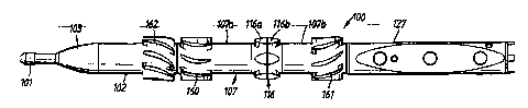
Figure 1 is a plan view of an embodiment of a
downhol2~top1 for generating pressure pulses in a drilling
fluid;
Figures 2A, ZB and ZC together show a longitudinal
cross-sectional view of the tool of Figure 1; and
Figure 3 shows detail. of the blade arrangements on
the tool o~ Figure 1.
bETAILED DESGItIPTION OF THE DRAWINGS
A preferred embodiment of the invention is shown
in the Figures. A downhole tool, generally indicated by
reference numeral 100 has a streamlined casing 103 facing
into the downward flow of drilling fluid. A standard
fishing end 101 extends from the casing, and permits the
tool to be manipulated or to be retrieved should the tool
need to be brought to the surface. A pressure balance
housing or stator 102 extends downstream of the casing 103
and a rotatable sleeve 107 extends downstream of the stator.
A stationary inner sleeve 124 extends coaxially with the
rotatable sleeve 107, as shown in Figure 2B_ Towards its
upstream end, the rotatable sleeve is sealed against the
stator 102 by a seal 104, and is supported on the inner
sleeve by bearings 7.06. Towards its downstream end, the
- 7
r1 :, '7 .n ,,_~
~~ ~L '~/ ;? c3 ,.J e1
rOtatable sleeve is sealed against an escapement housing 1.77
by a seal 144, and is supported on the inner sleeve by a
bearing 105, while the escapement housing 1Z7 is held fast
with the inner sleeve by means of a retaining nut 1Z2. The
seals 104 and 144 prevent ingress of drilling fluid to the
bearings 106 and 105 respectively.
The rotatable sleeve 107 has formed thereon a
number of blades 116, each blade comprising a front blade
section 116a and a rear blade section 116b. The rotatable
sleeve is split in a plane normal to the longitudinal axis
of the tool such that the rear portion 107b of the rotatable
sleeve and the front poxtion 107a of the rotatable sleeve
can rotate relative to each ether, and. thus the rear blade
section 116b and the ~rotlt blade section 116a can rotate
relative.to each other. When the front and rear blade
sections are aligned they form a set of streamlined blades,
between which the drilling fluid can flow with a low drag
coefficient. The shape of each aligned blade can be seen
most clearly in the solid lines shown in Figure 3. When the
relative rotation of the front and rear blade sections is
such that the rear blade sections lxe in a position of
misalignment with respect to the front blade Sections, as
shown in the broken outlines in Figure 3, the drag
coefficient is gxeatly increased, and a pressure pulse is
transmitted through the drilling fluid.
A set of driv~.ng blades 160 is provided on the
front portion 107a of the rotatable sleeve upstream of the
pulse-generating blades i16, and a further set of driving
blades 161 is provided on the rear portion 107b of the
rotatable sleeve dpwnstream of the pulse-generating blades
116. The two Sets of driving blades 160, 161 are curved
relative to the direction of flow of the drilling Fluid,
such that the resulting lift component acting on the blades
tends to rotate the front and rear portions of sleeve 107
about the inner sleeve 124. Thus a continuous torque is
supplied to the blade sections 116a and 116b, and the main
t' ; ~ '-) '.~ C9
~~ _t ~.~ ;; :r -.i
- g
driving force for creating the pressure pulses is derived
directly from the energy in the drilling fluid, so that the
additional energy requirement front dowrihole batteries or a
turbine is very low.
Each front blade section has a generally planar
rear end 112 extending generally normal to the direction of
fluid flow arid each rear blade section has a generally
planar forward end 115 extending generally normal to the
direction of fluid flow. These rear and forward ends 112
anti 115 form adjacent faces of the blade sections when the
blade sections are aligned, and preferably comprise a layer
of wear resistant material which reduces abrasion of the
faces of the blade sections.
Additional bearings 109 support the front and
rear portions of the rotatable sleeve 107 on the inner
sleeve 124, and seals 125 are grovided between the inner .
sleeve and the rotatable sleeve close to the split in the
rotatable sleeve_
A camshaft 111 is received within the inner sleeve
124 such that it can rotate coaxially within the inner
sleeve on needle roller bearings 108 at the forward end of
the camshaft and on deep groove ball bearings 128 at the
downstream end of the camshaft. The ball bearings 128 are
mounted between the Camshaft and the retaining nut 122 which
supports the escapement housing 127 on the inner sleeve 124.
Two additional sets of needle roller bearings 126a and 126b
are provided along the length of the camshaft 111.
An escapement mechanism 129 is provided on the
downstream end of the camshaft. The~escapement mechanism
comprises an escapement wheel 130, and a catch 131_ The
escapement mechanism is operated by a solenoid 121 having a
plunger 138. The catch 131 is connected to a catch link 132
which in turn is connected to a rocking arm 133. The
plunger 138 is connected to the rocking arm 133 by means of
a link 136_ The catch 131 is operable to move into and out
oL engagement with the escapement wheel 130 by means of the
solenoid plunger 138. A return spring 134 also acts on the
~~~T~~~~n~
~.J~~;.~.; 3
y _
plunger such that the solenoid pulls the plungar in one
dzr_ectzon, and the spring 134 provides tha return force in
the opposite direction. Alternatively, the escapement
mechanism may comprise a ratchet and a pawl, the pawl bezng
linked to the plunger of a tubular solenoid, as Shown in oux
copending British Patent Application 9120&54.6, or may be
provided by any other suitable arrangement. The cam shaft
111 has a number of lugs 113 spaced equi-angularly around
its circut~tfexence, and the inner sleeve 124 is provided with
a number of longitudinal slots 114, 115 in each of which are
positioned two escapement rollers 110. The rollers 110 in
longitudinal s~.ots 114 cooperate with the front portion 107a
of the rotatab~.e sleeve, and the rollers in longitudinal
slots 115 cooperate with the rear portion of the rotatable
sleeve. ,The rotatable sleeve has internally projecting
teeth 142. As the camshaft rotates, a lug I13 engages an
inner roller 110a and cams it outwards, thus also ramming
outer roller 110b outwards such that it protrudes beyond the
outer edge of inner sleeve 124 and znto the path of internal
teeth 142 on rotatable sleeve 107. Thus, as front portion
107a or rear portion 107b rotates under the constant torque
provided by the driving blades 160, 161 an internal tooth
142 engages outer roller 110b and further rotation is
prevented until the camshaft is moved on.
The camshaft escapement mechanism is operated to
release the camshaft and, when the cam shaft is freed, it
rotates under the continuous torque supplied by the driving
blades until the camshaft is locked in a stationary position
once more.
Controlling the movement of the camshaft controls
the,movement of the rotatable sleeve to incremental steps of
rotation. The rear portion 107b moves in a first direction
of rotation through a predetermined angle and then the Front
portion 107a moves through that angle in the same direction,
Such that rear blade portions 116b move from a position
where they are aligned with the front blade portions to a
position of maximum misalignment, and then the front blade
~~~~~ Z~s
~- 1 d
F~ortions 116a move from the misali4ned position back into
alignment with the rear blade portions, z_e. the rear blade
portions move out of alignment when the camshaft is released
and thcn the ~ront bl~dC portxpnp ,no:_~ tQ patch thorn up tho
next time the camshaft is released.
As previously discussed, with the arrangement of
blades described so fax, the flow of drilling fluid emerging
from the first set of d7riving blades 160 has developed a
swirling motion as a result of its action on the driving
blades 160. This swirling motion causes the fluid to act on
the blades 116 in the direction opposite to that in which
the front and rear blade sections 116a, 116b are being
driven to generate the pressure pulses, and the pulse
generation may therefore be affected. In order to overcome
this difficulty, an additional set of curved blades 16Z is
provided on the stator lOx upstream of the driving blades
160.
The stator blades 162 are curved in the opposite
direction to the curvature of the driving blades 160, 161,
as can be most clearly seen in figure 3. Thus incoming
fluid indicated by arrows 163 is deflected by the stator
blades 162 and flows into the driving blades 160 with a
swirling motion indicated by arrows 164. Because the
driving blades 160 are curved in the opposite direction to
the stator blades 162 swirl in the opposite direction is
imparted to the fluid by the driving blades 160, and thus
the swirling motion is substantially cancelled out and the
fluid emerges from the driving blades in an axial direction
as indicated by arrows 165. The fluid thus passes through
the half blades' 116 in an axial direction without impeding
the operation of the half blades, and the fluid flows into
the further set of driving blades 161 as indicated by arrows
166, acts on the driving blades 167. to genexate the
necessary torque and emerges from the driving blades with a
swirling motion indicated by arrows 167.
The particular shape and position of the stator
blades 162 and the driving blades 160, 161 should be
~~ .!. t~ '.." ~,i ', l il
- 11 -
Selected to minimise the swixling motion of the fluid
through the blades 116.
Although the present invention has been discussed
particularly as an improvement to the tool disclosed in our
copending British Patent Application No. 9120$54.6, clearly
curved stator blades of the present invention, or other
means of removing swirl from the fluid flow, could be used
to improve the performance of any pressure pulser having
curved driving blades or other swirl-producing means
upstream of the pulse generating blades.
Preferably, means are provided for reducing
tprsional vibration of the rotat~le sleeve by a damping
fluid such as oil contained within the rotatable sleeve.