Sélection de la langue

Search

Sommaire du brevet 2110067 

Énoncé de désistement de responsabilité concernant l'information provenant de tiers

Une partie des informations de ce site Web a été fournie par des sources externes. Le gouvernement du Canada n'assume aucune responsabilité concernant la précision, l'actualité ou la fiabilité des informations fournies par les sources externes. Les utilisateurs qui désirent employer cette information devraient consulter directement la source des informations. Le contenu fourni par les sources externes n'est pas assujetti aux exigences sur les langues officielles, la protection des renseignements personnels et l'accessibilité.

Disponibilité de l'Abrégé et des Revendications

L'apparition de différences dans le texte et l'image des Revendications et de l'Abrégé dépend du moment auquel le document est publié. Les textes des Revendications et de l'Abrégé sont affichés :

  • lorsque la demande peut être examinée par le public;
  • lorsque le brevet est émis (délivrance).
(12) Brevet: (11) CA 2110067
(54) Titre français: ACCELERATEUR D'ELECTRONS A CAVITE COAXIALE
(54) Titre anglais: ELECTRON ACCELERATOR HAVING A COAXIAL CAVITY
Statut: Périmé et au-delà du délai pour l’annulation
Données bibliographiques
(51) Classification internationale des brevets (CIB):
  • H05H 9/00 (2006.01)
  • H05H 7/18 (2006.01)
(72) Inventeurs :
  • JONGEN, YVES (Belgique)
(73) Titulaires :
  • ION BEAM APPLICATIONS SOCIETE ANONYME
(71) Demandeurs :
  • ION BEAM APPLICATIONS SOCIETE ANONYME (Belgique)
(74) Agent: GOWLING WLG (CANADA) LLP
(74) Co-agent:
(45) Délivré: 2001-12-11
(86) Date de dépôt PCT: 1992-05-27
(87) Mise à la disponibilité du public: 1992-12-10
Requête d'examen: 1999-03-22
Licence disponible: S.O.
Cédé au domaine public: S.O.
(25) Langue des documents déposés: Anglais

Traité de coopération en matière de brevets (PCT): Oui
(86) Numéro de la demande PCT: PCT/BE1992/000023
(87) Numéro de publication internationale PCT: WO 1992022190
(85) Entrée nationale: 1993-11-25

(30) Données de priorité de la demande:
Numéro de la demande Pays / territoire Date
9100516 (Belgique) 1991-05-29

Abrégés

Abrégé anglais


An electron accelerator having a first source emitting an electron
beam to be accelerated, and a coaxial cavity defined by an outer cylindrical
conductor and an inner cylindrical conductor lying on a single axis and joined
by
two flanges, wherein the electron beam is injected in the mid-plane which is
perpendicular to the axis along a first diameter of the outer conductor. The
accelerator is characterized in that it comprises a second source emitting an
electron beam which decelerates as it passes through the coaxial cavity,
whereby
the electromagnetic field required to accelerate the electron beam from the
first
source is produced.

Revendications

Note : Les revendications sont présentées dans la langue officielle dans laquelle elles ont été soumises.


CLAIMS
1. Electron accelerator, comprising:
a first source emitting an electron beam to be accelerated,
a coaxial cavity defined by an outer cylindrical conductor and an
inner cylindrical conductor, of the same axis, joined by two flanges, the
electron
beam being injected in the mid-plane which is perpendicular to the axis, along
a
first diameter of the outer conductor,
the accelerator being characterized in that it includes a second source
emitting a second electron beam, this electron beam being decelerated when it
passes through the coaxial cavity,
making it possible to produce the electromagnetic field necessary for
accelerating the first electron beam from the first source.
2. Electron accelerator according to claim 1, characterized in that the
second electron beam is injected into the coaxial cavity along a plane which
is
different from the mid-plane, thus allowing the electrons to be deflected
towards
the walls of the cavity.
3. Electron accelerator according to claim 1 or 2, characterized in that
the second source is provided with a device for modulating the intensity of
the
electron beam.
4. Electron accelerator according to any one of the preceding claims,
characterized in that it includes at least one electron deflector placed
outside the
cavity, which receives the first beam which has passed through the cavity,
deflects
it and reinjects it into the cavity, still in the midplane, along a second
diameter of
the outer conductor.

Description

Note : Les descriptions sont présentées dans la langue officielle dans laquelle elles ont été soumises.

r~ 2110067
SLBCTRON ACCELERATOR BAVINC3 A COA7CIAL CAVITY
Sub j ect of the invewtion
The present invention relates to improvements
made to electron accelerators, and more particularly to
electron accelerators having s coaxial cavity.
Tlaanri ~t ~ ~ of the prior art
Electron accelerators ara generally known, having
a resonant cavity supplied by a high-frequency field
source commonly called the HF generator, and an electron
source capable of injecting these electrons into the
cavity. If certain phase and frequency conditions are
respected, these electrons are accelerated by the elec-
tric field throughout their passage through the cavity.
These are in general machines working is the
pulsed regime, and having relatively low beam
intensities.
In document WO-A-88/09597 (Atomic Energy
Commission), an electron accelerator with recirculatioa,
of novel design, was proposed.
This document describes sn electron accelerator
which is characterized is that the resonant cavity is a
coaxial cavity defined by an outer cylindrical conductor
and as inner cylindrical conductor having the same axis.
The electron beam is injected into this cavity in the mid
pleas which is perpendicular to the axis, along a first
diameter. An electron deflector makes it possible to
deflect the beam once it has gassed through the cavity a
first time, and reiaject it back into the cavity where it
undergoes a second acceleration, etc:
This device is also called a rhodotroa because
the electron beam passes through the cavity several times
along a trajectory which describes the pattern of the
petals of a flower.
This device has several advantages, gamely that
its shape is particularly simple and compact. Ia
addition, the principle according to which the device
functions makes it possible to obtain an intense and
continuous beam, which was not the case with conventional

X110067
- 2 -
devices working is the pulsed regime.
Furthermore, the device described is salf-
focusiag. This is due to the fact that the magnetic
deflectors, which have input phases in the shaperof vary
wide dihedra provide suitable focusing of the electron
beam. It is consequently not necessary to provide addi-
tional focusing elements.
Finally, the alectroa beam injected in the mid
plaae of the device is not deviated. This is because the
beam is sot subjected to the magnetic field, which is
zero in the mid-plans according to the configuration
described in the abovementioned document.
However, this electron accelerator requires the
cavity to be supplied by a high-frequency field source.
In particular, in the device described, an electric field
of several hundreds of megahertz is gsneratad by as
external high-frequency generator.
These high-frequaacy generators, with a power of
approximately 200 kW, which can create electric fields of
several hundreds of megahertz are relatively expensive ~.
devices. They asseatially use electron tubes of the
triode, tetroda or pentods type, sad use advanced,
therefore expensive, technigusa such as metal/ceramic
welding, the use of refractory material grids or the use
of thoriated tungsten filaments.
Document tT8-A-4,763,079 describes a method for
decelerating a particle beam. in which the energy pro
duced by the deceleration of the particles is stored in
order to be used for accelerating electrons in another
accelerator.
Obi ect of the i,avention
The ob j ect of the present invention is to provide
a device which makes it possible to avoid the use of
particularly expensive high-fraqueacy generators, whilst
retaining the advantages intrinsic to the original
arrangement of the electron accelerator of the type
described in document WO-A-88/09597.
Priaciaal characteristic elemaats
The present invention relates to as electron

-~ 2110067
- 3 -
accelerstor~ comprising:
- a first source emitting an electron beam to be
accelerated,
- a coaxial cavity defined by an outer cylindrical
conductor and as inner cylindrical conductor, of
the same axis the electron beam being injected
in the mid-plane which is perpendicular to the
axis along a first diameter of the outer coaduc
tor~
the accelerator being characterized in that it includes
a second source emitting as electron beam, this electron
beam being decelerated whoa it passes through the coaxial
cavity making it possible to produce the electromagnetic
field necessary for accelerating the electron beam from
the first source.
This second electron beam is injected into the
coaxial cavity along a plane which is different from the
mid-plane, which makes it possible to deflect the elec
trons towards the walls of the cavity and to remove them
from this cavity.
The second electron source is provided with a
device making it possible to modulate the intensity of
the electrons emitted, is particular a control grid or a
rearraager. Such devices are well known is apparatuses
using electron beams. The intensity of the electron beam
is modulated such that the electrons from the second
source appear in the cavity at the moment when they
encounter a decelerating radial electric field. In this
way, the electrons give up their kinetic energy to the
electromagnetic field in the cavity and establish sad
hold the electromagnetic field. The energy of the.elec-
trons injected by the second source is preferably chosen
so that these electrons reach the wall of the cavity. with
a low but non-zero residual energy. In this way, the
energy conversion betweexi the electron beam and the
cavity can reach values of SO to 90%.
Hrief der~~criptioca of the figures
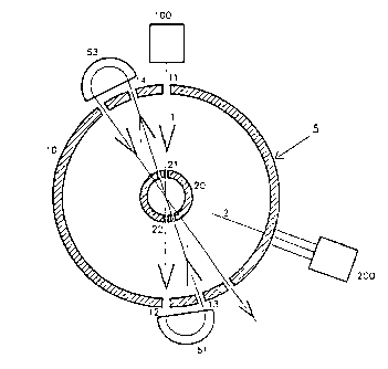
- Figure 1 represents a section along the mid-plane
of as accelerator having a coaxial

'"' - 4 - X110067
cavity.
- Figure 2 represents a half-view of a section
parallel to the principal axis of the
coaxial cavity of as electron accelerator
according to the present invention.
Description of a oartiaular em~bodis~ent of the ~raa~
invention
Figure 1 represents a section along the mid-plane
of the coaxial cavity of the electron accelerator
according to the present invention.
The cavity 5 is defined by as outer cylindrical
conductor 10 and as inner cylindrical conductor 20, of
the same axis, and two flanges 15 and 25 perpendicular to
the axis 30 of the conductors.
According to this configuration, the electric
field E is purely radials it is maximum is the mid-place
40 and decreases on either side of this plane to vanish
oa the flanges 15 and 25. Similarly, the magnetic field
M is maximum along the flanges and vanishes is the mid-
plane while changing sign.
The principal electron beam 1 is injected from a
source 100 into the coaxial cavity 5 along the mid-
plane 40, and is therefore subjected to ao deviation
because the magnetic field M is there equal to zero.
The electron beam 1 penetrates into the cavity
through as aperture 11 along a first diameter of the
outer conductor lOt it passes through the inner conductor
20 through two diametrically opposite apertures 21 and 22
and leaves the cavity through as aperture 12.
If certain phase and frequency conditions are
satisfied, the principal beam 1 will be accelerated over
its entire passage through the coaxial cavity 5.
In particular, it is suitable for the electric
field E to vanish when the beam passes through the inner
conductor 20, so that the field causes acceleration
during passage through the first part of the cavity
(between the outer conductor 10 and the inner
conductor 20). and again causes acceleration, being
therefore opposite, during passage over the second part

- 5 - 211006'7
of the trajectory. that is to say between the inner
conductor 20 and the outer conductor 10.
At least one deflector 51 is arranged outside the
coaxial cavity 5, which deflector deflects the principal
electron beam 1 and reinjects it along a second diameter
of the outer conductor 10. This beam is reintroduced
through as aperture 13 into the cavity where it again
undergoes acceleration and re-emerges through the
aperture 14.
When it leaves. the beam is again deflected by a
deflector 53 and reinjected along a third diameter into
the cavity, where it will undergo a third acceleration,
etc.
The magnetic deflectors 51, 53,... advantageously
have input faces in the shape of a very wide dihedron, so
as to focus the principal electron beam 1.
Figure 2 represents a half-view in section
parallel to the principal axis of the coaxial cavity.
According to the principal characteristic of the
present invention, the electron accelerator having a
coaxial cavity includes a second source 200 provided with
a device 210 for modulating the beam intensity, which
emits as electron beam 2 which will be injected into the
cavity 5 at the mameat whoa the electric field E causes
deceleration. This makes it possible to generate the
electromagnetic field neceasary for accelerating the
first electron beam 1.
The kinetic energy loss of the electron which is '
decelerated makes it possible to create a high-frequency
electromagnetic field is the coaxial cavity 5.
Preferably, this second electron beam 2 is
injected into the coaxial cavity 5 along a plane which is
different from the mid-plane 40. The result of this is
that the electrons will be deflected towards the walls of
the cavity, which allows them to be removed from the
cavity.
It is suitable for'the electrons not to be slowed
to rest is the cavity itself, because is this case the
electrons are again subjected, in the opposite direction,

- X110067
to the acceleration of the eleetromagaetic field, sad are
therefore reaccelerated.
Ia consequence, it is necessary for the electrons
from the secondary beam Z still to have some degree of
residual kinetic energy, so as to roach the walls of the
cavity 5.
Because of this, the degree of conversion of the
kinetic energy of the electrons into electromagnetic
energy is limited to values of from 80 to 90%.
This procedure advantageously makes it possible
not to have to resort to using external high-frequency
generators, which are particularly expensive devices. Ia
fact. they represaat approximately 30% of the total cost
of sa electron accelerator.
Furthermore, the structure of an accelerator
according to the present iavsation is simplified which
provides s non-negligible improvement is the reliability
of the electron accelerator.

Dessin représentatif
Une figure unique qui représente un dessin illustrant l'invention.
États administratifs

2024-08-01 : Dans le cadre de la transition vers les Brevets de nouvelle génération (BNG), la base de données sur les brevets canadiens (BDBC) contient désormais un Historique d'événement plus détaillé, qui reproduit le Journal des événements de notre nouvelle solution interne.

Veuillez noter que les événements débutant par « Inactive : » se réfèrent à des événements qui ne sont plus utilisés dans notre nouvelle solution interne.

Pour une meilleure compréhension de l'état de la demande ou brevet qui figure sur cette page, la rubrique Mise en garde , et les descriptions de Brevet , Historique d'événement , Taxes périodiques et Historique des paiements devraient être consultées.

Historique d'événement

Description Date
Inactive : CIB de MCD 2006-03-11
Le délai pour l'annulation est expiré 2003-05-27
Lettre envoyée 2002-05-27
Accordé par délivrance 2001-12-11
Inactive : Page couverture publiée 2001-12-10
Inactive : Taxe finale reçue 2001-09-05
Préoctroi 2001-09-05
Un avis d'acceptation est envoyé 2001-05-23
Lettre envoyée 2001-05-23
Inactive : Approuvée aux fins d'acceptation (AFA) 2001-05-11
Inactive : Dem. traitée sur TS dès date d'ent. journal 1999-04-14
Inactive : Acc. réc. RE - Pas de dem. doc. d'antériorité 1999-04-14
Inactive : Renseign. sur l'état - Complets dès date d'ent. journ. 1999-04-14
Toutes les exigences pour l'examen - jugée conforme 1999-03-22
Exigences pour une requête d'examen - jugée conforme 1999-03-22
Modification reçue - modification volontaire 1999-03-22
Demande publiée (accessible au public) 1992-12-10

Historique d'abandonnement

Il n'y a pas d'historique d'abandonnement

Taxes périodiques

Le dernier paiement a été reçu le 

Avis : Si le paiement en totalité n'a pas été reçu au plus tard à la date indiquée, une taxe supplémentaire peut être imposée, soit une des taxes suivantes :

  • taxe de rétablissement ;
  • taxe pour paiement en souffrance ; ou
  • taxe additionnelle pour le renversement d'une péremption réputée.

Veuillez vous référer à la page web des taxes sur les brevets de l'OPIC pour voir tous les montants actuels des taxes.

Historique des taxes

Type de taxes Anniversaire Échéance Date payée
TM (demande, 5e anniv.) - générale 05 1997-05-27 1997-05-26
TM (demande, 6e anniv.) - générale 06 1998-05-27 1998-05-07
Requête d'examen - générale 1999-03-22
TM (demande, 7e anniv.) - générale 07 1999-05-27 1999-05-04
TM (demande, 8e anniv.) - générale 08 2000-05-29 2000-04-28
TM (demande, 9e anniv.) - générale 09 2001-05-28 2001-03-30
Taxe finale - générale 2001-09-05
TM (demande, 2e anniv.) - générale 02 1994-05-27
Titulaires au dossier

Les titulaires actuels et antérieures au dossier sont affichés en ordre alphabétique.

Titulaires actuels au dossier
ION BEAM APPLICATIONS SOCIETE ANONYME
Titulaires antérieures au dossier
YVES JONGEN
Les propriétaires antérieurs qui ne figurent pas dans la liste des « Propriétaires au dossier » apparaîtront dans d'autres documents au dossier.
Documents

Pour visionner les fichiers sélectionnés, entrer le code reCAPTCHA :


Pour visualiser une image, cliquer sur un lien dans la colonne description du document. Pour télécharger l'image (les images), cliquer l'une ou plusieurs cases à cocher dans la première colonne et ensuite cliquer sur le bouton "Télécharger sélection en format PDF (archive Zip)" ou le bouton "Télécharger sélection (en un fichier PDF fusionné)".

Liste des documents de brevet publiés et non publiés sur la BDBC .

Si vous avez des difficultés à accéder au contenu, veuillez communiquer avec le Centre de services à la clientèle au 1-866-997-1936, ou envoyer un courriel au Centre de service à la clientèle de l'OPIC.


Description du
Document 
Date
(aaaa-mm-jj) 
Nombre de pages   Taille de l'image (Ko) 
Page couverture 1995-05-27 1 53
Description 1995-05-27 6 402
Revendications 1995-05-27 1 77
Description 1999-03-21 6 283
Revendications 1999-03-21 1 44
Abrégé 1995-05-27 1 19
Dessins 1995-05-27 1 25
Page couverture 2001-11-16 1 40
Revendications 1999-03-22 1 39
Dessin représentatif 2001-11-16 1 9
Dessin représentatif 1999-08-24 1 9
Rappel - requête d'examen 1999-01-28 1 116
Accusé de réception de la requête d'examen 1999-04-14 1 173
Avis du commissaire - Demande jugée acceptable 2001-05-23 1 164
Avis concernant la taxe de maintien 2002-06-25 1 177
PCT 1993-11-25 31 1 263
Taxes 1998-05-07 1 44
Correspondance 2001-09-05 1 34
Taxes 2001-04-04 1 32
Taxes 1997-05-26 1 49
Taxes 1999-05-04 1 41
Taxes 2000-04-28 1 39
Taxes 1996-03-14 1 36
Taxes 1994-05-13 1 39
Taxes 1995-04-27 1 36