Note : Les descriptions sont présentées dans la langue officielle dans laquelle elles ont été soumises.
I
CA 02110372 2004-11-23
1
REMOVABLE DAMPER FOR CHEMICAL RECOVERY FURNACE
Backcrround of the Invention
The present invention relates to furnaces and
particularly to apparatus comprising a removable
damper for an air port of a chemical recovery furnace.
Wood pulp for paper making is usually
manufactured according to the sulfate process
wherein wood chips are treated with a cooking liquor
including sodium sulfide and sodium hydroxide. The
wood chips and the cooking liquor, called "white
liquor", are cooked in a digester under
predetermined heat and temperature conditions.
After cooking, the used liquor, termed "black
liquor", containing spent cooking chemicals and
soluble residue from the cook, is washed out of the
pulp and treated in a recovery unit where the
cooking chemicals are reclaimed. Without reclama-
tion and reuse of the cooking chemicals, the cost of
the paper making process would be prohibitive.
In the recovery process, the black liquor is
first concentrated by evaporation to a water
solution containing about sixty-five percent solids,
which solution is then sprayed into the firebox of a
black liquor recovery boiler, a type of chemical
reduction furnace. The chemical reduction furnace
is a reactor wherein the processes of evaporation,
gasification, pyrolysis, oxidation and reduction all
occur interdependently during recovery of the
cooking chemicals. The.organic materials in the
black liquor, lignin and other wood extracts,
maintain combustion in the firebox, and the heat
CA 021110372 2004-11-23
2
produced melts the spent cooking chemicals. A
molten smelt flows out of the furnace through a
smelt spout to a collection tank. Concurrently,
combustion heat is employed to generate steam in a
wall of boiler tubes for use as process steam and
for generating electricity.
The combustion process requires the introduction
of large volumes of air into the firebox, air
comprising about eighty percent of the material
entering the furnace. The air is forced into the
firebox from windboxes or ducts disposed at several
levels in surrounding relation to the firebox,
through a plurality of air ports in the walls of the
furnace; while there are variations, the principal
ones are primary, secondary and tertiary air ports.
The primary air ports are always the smallest
and most numerous and are disposed on the four
walls of the firebox near the bottom of the furnace
and close to the char bed. The air supplied to the
primary air ports is usually at a comparatively low
pressure, and provides a portion of the air for
char bed combustion and is used to control the shape
and position of the perimeter of the char bed.
Secondary air ports, which are generally larger and
fewer in number than the primary air ports are
generally disposed around the walls of the firebox
higher than the primary air ports and usually below
the level of the liquor spray nozzle. Air supplied
through the secondary air ports is at a higher
pressure than the primary and is used to control
the position of the top of the char bed and to
promote burning of combustible gasses rising from
the char bed. Typically 65 to 80 percent of the
total combustion air to the recovery boiler is
introduced below the liquor spray nozzles. The
CA 021110372 2004-11-23
3
tertiary air ports are located above the liquor
spray nozzles and are generally larger and fewer
yet in number than the secondary air ports. Air
supplied through the tertiary air ports is
generally at a still higher pressure to promote
complete combustion and final mixing of gasses
rising through the firebox.
The black liquor sprayed into the firebox,
having a consistency similar to that of warm sixty
weight oil, swirls, burns and falls toward the
bottom of the firebox as combustion products
comprising char material and smelt. The smelt and
char material contact the outer walls of the
firebox and, cooled by the inflowing air, form
excrescent deposits around the edges of the air
ports, particularly along the edges of the openings
where the excrescent material builds up under
influence of air rushing through the air port.
Such build-ups of char material can block air flow
through the ports and must be removed.
The volume and distribution of combustion air
supplied to the furnace is, however, varied
depending on many factors including the load of the
furnace and properties of the liquor being reduced.
The distribution and volume of air entering the
furnace are desirably adjusted by regulating means
such as dampers provided in supply ducts to the
windboxes, at various locations in the windboxes,
and at individual air ports for maintaining the
desired air supply in all parts of the furnace. Of
these three locations, the provision of regulated
dampers at the air ports is most desirable.
Providing dampers at individual air ports enables
the independent adjustment of mass air flow and air
pressure. This independence is key because mass
CA 021110372 2004-11-23
4
flow is primarily determined by load while windbox
pressure is determined by smelt bed conditions,
furnace geometry and air/fuel mixing needs and is
nearly independent of load. The mass air flow can
be controlled by controlling the relative size of
the port by adjusting the damper position, while
air pressure can be adjusted at a supply fan and by
means of dampers within supply ducts. As the
damper is closed, the aspect ratio for the air
port, which is ordinarily elongated, can be made to
approach equal width and height dimensions for more
closely simulating a round jet of air. Such a jet
is advantageous at the primary air port level as
well as at secondary and tertiary air port levels
because it is most energy efficient which optimizes
combustion control. A more efficient jet also
provides better control of the smelt bed and
maintains a cleaner windbox inasmuch as cleanliness
of the primary windbox is primarily affected by the
proximity of the smelt bed and smelt intrusion into
the windbox cavity. Maintaining a higher air
pressure also helps sweep the bottom of the windbox
and pushes the smelt away. Ability to control the
air jet from the individual air ports and operating
at higher windbox pressures further enables the
operator to correct for disturbances in the char
bed and otherwise correct the combustion process.
An advantageous damper construction is of the
sliding or guillotine type which facilitates the
control of the air port aspect ratio in the manner
above mentioned whereby a comparatively high
pressure jet of air can be produced. Conventional
guillotine dampers operate with a pivot point
located inside the windbox and slide in a track
proximate the air port, the operating mechanism for
CA 02110372 2004-11-23
the damper being contained within the windbox.
The air port area is subject to smelt intrusion,
thermal expansion, and warping, as well as long
periods without use, causing the damper mechanisms
to become frozen in a particular position,
particularly at the primary air port level.
Removal or servicing of the damper can be
difficult or impossible without closing down the
furnace.
Summary of the Invention
In accordance with the present invention,
rather than being attached to the inside of the
windbox or to the tube wall of the furnace
adjacent the air port, dampers are instead
supported in cantilever fashion from a windbox
faceplate located on the opposite side of the
windbox from the air port. This windbox
faceplate is adapted for removable attachment
over an opening in the forward side of the
windbox and carries the damper mechanism with it
when removed.
A cantilevered arm is preferably pivotally
mounted to the exterior side of the faceplate but
extends through an aperture in the faceplate to
the interior of the windbox where the cantilevered
arm is provided with a damper blade. The
cantilevered arm also includes a biasing mechanism
for urging the damper blade toward the air port in
slidable but unattached relation to the windbox or
tube wall. The position of the damper blade is
controlled to be in blocking relation to a portion
of the air flow through the air port in accordance
with the pivotal attitude of the cantilevered arm,
whereby the desired air port cross section and air
CA 021110372 2004-11-23
6
flow is achieved. However, the damper blade is
free to move in a direction substantially
perpendicularly away from the air port so it can be
moved away from the air port and so that when the
windbox faceplate is removed outwardly away from
the windbox, the cantilevered arm and damper blade
are carried therewith such that corrective cleaning
of smelt material can be accomplished. It is also
found that the damper blade in accordance with this
construction can be adjusted without sticking as
would be the case if it were carried in a track,
with the blade tending to ride up over smelt
deposits as necessary until they are cleaned away.
The aforementioned cantilevered arm preferably
extends from a horizontal shaft disposed on the
exterior side of the faceplate which is rotated by
mechanism also mounted exteriorly. Therefore, the
mechanism is readily available for maintenance and
adjustment.
A plurality of damper blade mechanisms are
suitably mounted on the same faceplate, together
with air port cleaner mechanism for rodding the air
ports periodically whereby smelt build-up in the
air ports can be removed. The damper blades are
operated in a coordinated manner with the air port
rodding apparatus whereby the dampers are
periodically fully opened, i.e., during a cleaning
sequence, and then restored to an operator preset
position designed to achieve the preferred mass
flow and velocity of jet through the air port.
It is accordingly an object of the present
invention to provide an improved damper control for
air ports of a chemical recovery furnace.
It is another object of the present invention
to provide improved dampers for a chemical recovery
i
CA 02110372 2004-11-23
7
furnace which are readily removable for cleaning or
maintenance.
It is another object of the present invention
to provide improved damper mechanism for a chemical
recovery furnace which is readily adjustable to
different air mass flow settings.
It is a further object of the present
invention to provide an improved removable damper
for a chemical recovery furnace which is adaptable
for primary air port use.
It is another object of the present invention to
provide an improved combination damper and cleaning
device for ports of a chemical recovery furnace.
The subject matter of the present invention is
particularly pointed out and distinctly claimed in
the concluding portion of this specification.
However, both the organization and method of
operation, together with further advantages and
objects thereof, may best be understood by
reference to the following description taken in
connection with accompanying drawings wherein like
reference characters refer to like elements.
Drawings
FIG. 1 is a side view, partially in cross
section, of a combination damper apparatus and
cleaning device for air ports of a chemical
recovery furnace;
FIG. 2 is a partially broken-away view of the
same apparatus as depicted in FIG. 1, illustrating
a damper blade and cleaning rod in a second
position;
FIG. 3 is a plan view of the FIG. 1 apparatus;
FIG. 4 is a side view, partially in cross
section, of a combination damper apparatus and
i
CA 02110372 2004-11-23
cleaning device according to a second embodiment
of the present invention;
FIG. 5 is a partially broken-away view of the
same apparatus as depicted in FIG. 4, illustrating
a damper blade and cleaning device in a second
position;
FIG. 6 is a plan view of the FIG. 4 apparatus;
FIG. 7A is an end view, partially broken-away,
of a damper counter link and biasing spring as
employed in the FIG. 4 embodiment; and
FIG. 7B is a side view, partially broken away,
of the FIG. 7A counter link and biasing spring
combination.
Detailed Description
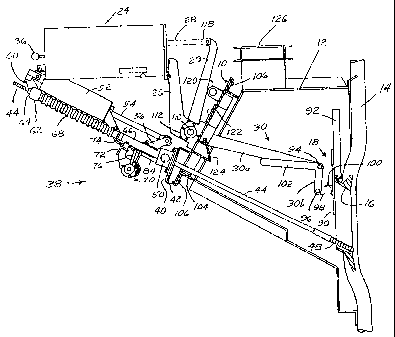
Referring to the drawings and particularly to
FIG. 1, a combination damper and cleaning apparatus
for air ports of a chemical recovery furnace is
illustrated as mounted upon a common, removable
windbox faceplate 10 of a windbox 12. Adjacent the
windbox and within the firebox of the furnace are
positioned a plurality of boiler tubes 14. Air ports
16 defined by cast metal frames are located for
passing quantities of combustion air from the windbox
outwardly into the firebox between the, boiler tubes.
Damper means 18, which is hereinafter more
fully described, is adapted for regulating the air
passing through the air ports by selectively
blocking off portions of the air ports. The
combustion air passes vertically into the windbox
12 from a supply duct thereabove via a feed duct
126 and beneath the damper through air ports 16.
In the position shown in FIG. 1, the air passage is
partially closed off in accordance with a
predetermined adjustment, blocking the flow of air
I
CA 02110372 2004-11-23
9
which could pass through an air port if the damper
were completely upraised. In the fragmentary view
of FIG. 2, damper means at 18' is illustrated in an
upraised position whereby, for example, access is
provided to the air port for a cleaning rod 44
having a cleaning tip 48.
In accordance with the present invention, a
damper controller 24, as more fully set forth in
co-pending application Serial No. 07/662,353 filed
February 28, 1991, now Patent No. 5,167,192 issued
December 1, 1992, is mounted upon bracket 26 which
is in turn secured to windbox faceplate 10. Damper
actuator rod 28 is connected by way of damper
actuator arm 29 to damper lever arms 30 for
operating damper means 18 as hereinafter more fully
described. The air controlling position of the
damper is determined via operating handle 36 of
damper controller 24.
The damper apparatus in accordance with the
present invention is adapted to be employed in
conjunction with an automatic air port cleaner of
the general type set forth in Goodspeed Patent
4,822,428 issued April 18, 1989. Such cleaner,
illustrated at 38, is mounted on plate 40 supported
from frame 42 upon windbox faceplate 10 so that
cleaning rods 44 extend into windbox 12. The
remote end of each rod 44 is equipped with cleaning
tip 48 used for cleaning an air port 16.
The rod 44 passes through pivot bearing 50
positioned over an aperture in plate 40 and
operable to enable pivoting of rod 44 and tip 48 in
a vertical direction, i.e., up and down over
substantially the vertical dimension of air port
16. Pivot bearing 50 and sleeve 66 carried thereby
slidably receive rod 44 so that it can be extended
CA 021110372 2004-11-23
1~
to the right in FIG. 1 whereby tip 48 is inserted
into the air port in a direction longitudinal of
rod 44. To accomplish rod extension, the apparatus
38 is equipped with an air cylinder 52 having a
piston rod 54 pivotally mounted upon a bracket 56
extending angularly upwardly from a member 66. The
opposite end of the air cylinder 52 is pivotally
mounted upon a bracket 60 which extends angularly
upwardly from bar 62 receiving the threaded inner
end of each rod 44, each rod 44 being engageable by
nut 64 secured against bar 62. A portion of rod 44
is covered by boot or bellows 68 to prevent
contamination thereof as it slides back and forth.
An eccentric mechanism 70 is adapted for
indexing the rods 44 and tips 48 to various angular
positions about the horizontal axis of each pivot
bearing 50. Referring to FIG. 2, rod 44 is shown
in a counterclockwise or upraised position and is
extended so that tip 48 protrudes outwardly through
air port 16 between the boiler tubes. The
eccentric mechanism 70 is capable of swinging the
rod 44 whereby tip 48, having the approximate width
of an air port, can clean the entire air port in
the vertical direction. Typically, the tip 48 will
first be in a position withdrawn to the left as
illustrated in FIG. 1 and will be then extended
outwardly to the right so as to clean a portion of
the air port. The tip is withdrawn to the left
again and indexed upwardly by mechanism 70 after
which it can be extended once more to the right.
Successive "ramming" operations, under control of
air cylinder 52, are effective for cleaning the
entire air port. The above cycle of events is
repeated periodically under automatic timing
control.
CA 02110372 2004-11-23
11
Eccentric mechanism 70 is supported by a bar
72 secured beneath sleeve members 66 which receive
cleaning rods 44, 44' and 44 " . A cam plate 74
attached to the input shaft of the eccentric
mechanism 70 by radial arm 76 is positioned for
engagement by roller 78 (FIG. 3) mounted on air
cylinder 52 so that when air cylinder 52 moves to
the left and retracts the cleaning rods, the input
shaft of eccentric mechanism 70 is rotated in a
counterclockwise direction. An eccentric wheel,
rotated in response to this rotation via clutch
means 80, is captured within ring 82 secured to arm
84 extending rearwardly and upwardly from plate 40.
Consequently, as cam plate 74 is rotated a fraction
of a revolution as a result of retraction of the
cleaning rods, the eccentric wheel will rotate a
fraction of a revolution within ring 82 and
displace the cleaning rods angularly upwardly (or
downwardly) to position them for the next ramming
operation in the same cycle.
As will be noted in FIG. 3, a total of three
rodding mechanisms in the illustrated embodiment
are mounted on one common faceplate and damping
means are provided for three adjacent air ports
leading from the same windbox to the furnace
firebox. Also the faceplate is suitably provided
with viewing windows 122 through which air ports
may be observed and closable manual rodding ports
124 that enable access entry for an elongated hand-
held cleaning implement, should a particular air
port cleaning problem arise that cannot be taken
care of by the automatically operable rods 44, or
in case of equipment failure. Rodding ports 124
provide access to the dampers as well, as
hereinafter more fully described.
I
CA 02110372 2004-11-23
12
The damper means 18 in FIG. 1 is illustrated
as positioned adjacent the air ports for blocking a
portion of the air flow. However, in FIG. 2 the
damper means as illustrated at 18' is shown in a
position withdrawn from the area immediately in
front of the air ports for placing the damper means
in non-interfering relation with operation of
cleaning rods 44. For this purpose, damper
actuator rod 28 has been translated to the left by
operation of controller 24, rotating arms 30 in a
counterclockwise direction for moving the dampers
out of the way, in this case to a fully-open
position. When the cleaning apparatus 38 has then
finished a given cleaning cycle and returns rods 44
to a resting position, damper means 18 can be
returned to the FIG. 1 damping position which was
initially selected by handle 36.
Damper means 18 in accordance with the present
invention comprise "guillotine" or vertically
sliding damper apparatus, in the present embodiment
comprising three vertically slidable flat metal
damper blades or plates 90, 90' and 90 " that are
vertically movable to cover and uncover air ports
16 disposed along the side of the windbox next to
the firebox of the furnace. As illustrated, the
damper blades each slide over a casting which forms
the frame for each air port 16, and along a damper
guide bar 92 secured at the top of each air port
frame and extending upwardly therefrom to support
the damper blade in its upraised position.
It will be noted that damper blades 90 are not
captured in tracks but are free to move in a
horizontal direction perpendicularly away from the
air ports. However, the damper blades are urged
toward the air port frames by damper arms 30, each
CA 021110372 2004-11-23
13
damper arm 30 comprising a cantilevered arm that is
pivotally mounted at the forward side of faceplate
10. The arms 30 are suitably spaced between the
cleaning devices and each arm 30 is articulated,
comprising a first portion 30a pivotally mounted to
the forward side of the faceplate away from the
windbox, and a second portion 30b connected to the
first portion by pivot 94. Each second arm portion
depends or extends downwardly from pivot 94 for
making a connection at another pivot point 96 with a
stub arm 98 extending from mounting bar 100 to which
damper plates 90, 90' and 90 " are attached. In
accordance with a first embodiment, arm portion 30b
is provided with an extension 102 located on the
opposite side of pivot 94 from the damper blade, the
extension 102 being sufficiently heavy to provide a
counterweight, wherein the combined weights of
extensions 102 more than balance the weights of the
damper blades 90, mounting bar 100, stub arms 98, and
the depending arm portions 30b, considering, of
course, the moment arms for each weight. Therefore,
the damper blade assembly comprising the respective
damper blades 90 and bar 100 is urged in a counter-
clockwise direction whereby the damper blades rest
against the respective air port frames, and damper
guide bars. The arm portions 30b and counterweight
extensions 102 are suitably bifurcated as illustrated
in FIG. 3 whereby the counterweight extensions 102
reside on either side of arm portions 30a. The
vertical position of the damper blades 90 is dependent
upon the angular position of arms 30a as determined by
damper controller 24. However, since the damper
blades are not captured in tracks, they are less
likely to become lodged in excrescent material.
Moreover, if excrescent material is formed at the
i
CA 02110372 2004-11-23
14
edges of the air ports, the damper blades 90 are
often able to ride up over the deposited material.
More significantly, a damper blade can be
temporarily swung away from an air port employing a
suitable cleaning implement extended through a
manual rodding port 124. Of further significance is
the fact that the entire mechanism including the
damper arms 30 and the damper blades 90 are
removable with the faceplate 10, the latter being
removably secured by fastening means 106 to frame
104 defining a forward opening in the windbox
opposite the air ports. The faceplate can be
uplifted by means of lugs 120. The whole apparatus
comprising controller 24 and cleaner 38 can be with-
drawn away from the windbox during furnace operation
for servicing, cleaning or replacement as desired.
The functioning of the furnace, and specific air
ports thereof, thus need not be impaired by continued
immovability or non-functioning of a particular
damper or group of dampers. It will be further
noted the cantilevered arms 30 as well as the rods
44 extend inwardly and downwardly away from the
faceplate to avoid substantial interference of
excrescent material with removal or servicing of the
apparatus.
As the damper arms move upwardly to slide the
damper blades 90 upwardly, i.e., as the arms rotate
in a counterclockwise direction, each arm portion
30b rotates in a clockwise direction relative to
arm portion 30a whereby the damper blades 90 move
vertically along the air ports and along damper
guide bars 92 to maintain contact without binding.
Thus, vertical sliding movement of the damper
blades is accommodated at the end of rotating arm
portions 30a even though the latter move in an arc.
1
CA 02110372 2004-11-23
The arm portions 30a are secured for rotation
with horizontal operating shaft 110 mounted on the
forward side of the faceplate (the side opposite the
air ports) by horizontally spaced bearing members
5 112. The arm portions 30a extend through apertures
114 in the faceplate and are joined to hubs 116
secured to shaft 110. Shaft 110 is in turn rotated
to the desired extent by means of damper actuator
arm 29 depending from clevis 118 at the end of
10 actuator rod 28 and terminating in a hub also
secured to shaft 110. The last mentioned hub
suitably comprises the same hub by means of which
one of the arm portions 30a is attached to shaft
110. It will be appreciated that maintenance and
15 repair of the operating portions of both the damper
control mechanism and the rodding cleaner mechanism
may in many instances be undertaken from the
exterior of the faceplate without disengaging the
faceplate from the windbox since the apparatus is
accessible on the exterior of the faceplate.
A second embodiment of the present invention
will be explained with reference to FIGS. 4, 5, 6,
7A and 7B. In FIGS. 4, 5 and 6, elements
identified by reference numerals corresponding to
those in FIGS. 1, 2 and 3 are substantially
identical to those previously described. In the
second embodiment, the biasing means for holding
the damper blades 90 against the air port openings
comprise torsional springs rather than
counterweights.
In this embodiment it will again be noted that
the damper blades 90 are not captured in tracks but
are free to move in a horizontal direction, perpen-
dicularly away from the air ports. The damper blades
are urged toward the air port frames via the damper
i
CA 02110372 2004-11-23
16
arms 130, each damper arm 130 comprising a canti-
levered arm that is mounted for rotation via shaft
110', wherein the latter is supported between bearing
members 112' that are secured to the forward side of
the face plate. The bearing members 112' support the
bearings for shaft 110' while also providing access
for arms 130 to shaft 110' on the windbox side where
the housings are open to the windbox through aper-
tures in the face plate over which the bearing members
are mounted. The bearing members 112' are closed
above the face plate to lessen the outflow of air.
The arms 130 are suitably spaced between the
cleaning devices, and specifically between rods 44,
and are articulated to provide first arm portions
130a rotatable with respect to the forward side of
the face plate, as well as depending counter links
130b that provide second arm portions laterally
offset with respect to the first arm portions.
The arm portions 130a at their distal ends
mutually support a lateral shaft 132 to which collars
134 and 136 are joined, proximate each damper counter
link 130b. (See FIGS. 7A and 7B.) Between each pair
of collars 134, 136, shaft 132 carries a hub 138 as
well as the upper apertured end of counter link 130b
at a location substantially in front of, a
corresponding air port opening, and between (or to
one side of) arm portions 130a. Torsional spring 140
wraps around hub 138 with one end of the spring
received through a peripheral bore in collar 136
while the other end engages the lower body of damper
counter link 130b for urging the counter link in a
clockwise direction, as the device is seen in FIG.
7B. The shaft 132 can be considered as forming part
of a first articulated arm portion which thereby
provides a second pivot point for the articulated arm.
CA 021110372 2004-11-23
17
Each damper counter link 130b is connected at
its lower end to a short shaft 142 carried between
ears 144 secured to a damper blade 90, each damper
counter link being provided with a lower hub 146
through which a shaft 142 extends. A damper blade
90 is thereby carried at the lower end of a damper
counter link 130b, and is rotatable about a pivot
point defined by shaft 142. The torsion springs
140 urge the damper counter links 130b toward the
air port opening and hold the damper blades in
secure but sliding relation against the frame that
defines the air port. The vertical position of the
damper blades 90 is dependent upon the angular
position of arms 130 as determined by damper
controller 24. However, since the damper blades
are not captured in tracks, they are less likely to
become lodged in excrescent material. As
hereinbefore discussed, if excrescent material is
formed at the edges of the air ports, the damper
blades 90 are often able to ride up over the
deposited material, and a damper blade can also be
swung away from the air port employing a cleaning
implement extended through manual rodding port 124.
Furthermore, the entire mechanism including the
damper arms 130 and the damper blades 9.0 is
removable with the face plate 10, the latter being
removably secured by fastening means 106 to frame
104 defining a forward opening in the windbox
opposite the air ports. The whole apparatus
comprising controller 24 and cleaner 38 can be
withdrawn away from the windbox during furnace
operation if desired.
As the damper arms move upwardly to slide the
damper blades 90 upwardly, i.e., as the arms rotate
in a counterclockwise direction, each damper
i
CA 02110372 2004-11-23
18
counter link 130b rotates in a clockwise direction
relative to an arm portion 130a (for the config-
uration shown) whereby the damper blades 90 move
vertically along the air ports and along damper
guide bars 92, making contact without binding.
Vertical sliding movement of the damper blades is
accomplished at the end of a rotating arm even
though the latter moves in an arc.
In the embodiment of FIGS. 4-7B, it will be
noted that damper controller 24 together with arm
29 as connected to shaft 110' are displaced some-
what to the right compared to the first embodiment
(as the apparatus is viewed by an individual facing
the windbox) to accommodate the position of bearing
members 112' located in line with arms 130. The
damper actuator arm 29 depending from clevis 118 at
the end of actuator rod 28 is secured to shaft 110'
outboard from the adjacent bearing member 112'.
However, the operation of the mechanism for rotat-
ing shaft 110' and moving arms 130 upwardly and
downwardly is substantially the same as described
with respect to the previous embodiment.
The torsional springs in this embodiment are
advantageously formed of high temperature stainless
steel. The springs have the advantage, of being
compact and are more easily replaceable to
accommodate differing degrees of torque as may be
required in different installations. Moreover,
they are lighter to lift and present less
interference with air flow. Torque may also be
controlled without replacement of the torsional
springs by adjustment of collar 136, which may be
loosened and rotated independently of shaft 132.
Once torque is adjusted to the desired level,
I
CA 02110372 2004-11-23
19
collar 136 is then tightened to fix the torque
at the desired level.
The damper counter links 130b, 130b' and 130b"
(FIG. 6) rotate individually relative to one another
thereby advantageously accommodating misalignment
between the respective port casings.
In accordance with the invention,
guillotine-type dampers or vertically slidable
dampers are provided for primary air ports of a
chemical recovery furnace and are advantageous in
adjusting the air port openings for optimum air
mass flow and jet velocity. The damper
construction is less apt to be fouled or locked in
position by excrescent material since the damper
blades are not captured in slots in the windbox,
and the entire mechanism is removable with the
windbox faceplate inasmuch as the blades are
cantilevered at the end of damper arms pivotally
attached to the faceplate. The blades can also be
moved.away from the air ports via a rodding port in
the faceplate. Furthermore, the cantilevered arms
are pivotally mounted to the exterior of the
faceplate whereby the rotating mechanism can be
readily serviced. The damper blades are also less
apt to bind since utilized in combination with
automatic cleaning apparatus that not only
periodically cleans the air ports but also
functions on a timed basis whereby the damper
blades are frequently moved and are therefore less
likely to become stuck in excrescent material.
Although the present mechanism has been
described with reference to primary air port
application, it will be readily appreciated the
same apparatus can be utilized in conjunction with
secondary or tertiary air ports. While preferred
I
CA 02110372 2004-11-23
embodiments of the present invention have been
shown and described, it will be apparent to those
skilled in the art that many other changes and
modifications may be made without departing from
5 the invention in its broader aspects. The appended
claims are therefore intended to cover all such
changes and modifications as fall within the true
spirit and scope of the invention.
15
25
35