Note : Les descriptions sont présentées dans la langue officielle dans laquelle elles ont été soumises.
PCT/AU92/00290
WO 92/Z2845
IMPROVED PATTERN TORIC LENS
The present invention relates to contact lenses and
more particularly relates to an improvement in the known
designs of contact lenses.
There are a number of lens designs presently in
existence which have design regimes which enable achievement
of various effects relating to interplay between the--cornea,
the lens and the eye lids of a wearer, espec ally in
assisting with lens orientation on the eye of a wearer.
In the past, lenses (which usually have a circular
appearance from a plan view and a concave outward appearance
from a side view) have had machining performed on them in
various ways in an attempt to provide a lens configuration
which will enable correct lens orientation on the eye as
well as adequate control of the lens on the eye of the
wearer. Traditionally, the correct lens orientation on the
eye has been achieved by providing on the lens surface,
machined prisms, wedges and truncations.
In implementation of these designs it is also necessary
for the designer to consider the requirement of transmission
of gas between the lens and the cornea. Low gas
transmission may create problems on the eye of a wearer
which stem from not allowing the eye to breathe.
A contact lens sits in apposition with the cornea or
the sclera or both. It is important that a lens be able to
transmit or allow a passage of oxygen to reach the eye so
that natural-conditions can be maintained as far as is
practical near the eye and on the eye surface. Proper
orientation of a lens on the eye is necessary for proper
correction of astigmatism.
When a lens is oriented in the proper direction, the
astigmatic error in the lens is closely coincidental with
the astigmatic error in the eye. It is essential that this
be achieved to prevent visual acuity deteriorating.
The prior art lenses achieve orientation by three main
ways. The first relates to prism formation on the lens.
This is achieved by machining of the lens surface to allow
the eye lids to complement the lens surface configuration
thereby assisting in proper location of the lens. In one
CA 02111466 2002-O1-30
2
configuration the lens is thickened towards the bottom.
The second method of lens orientation is achieved by zonal thinning. In this
case, the
top and bottom peripheral areas of the lens are thinned by machining. The eye
lid pressure
then moves the lens around to find the line of least resistance to thereby
hold the lens in the
correctly oriented position. The former method of lens orientation suffers
from a number of
disadvantages namely the aforesaid thickened portion of the lens may prevent
adequate
oxygen transmission through the lens. This can result in oedema or corneal
neovascularisation. Another consequence of the lens thickening is wearer
discomfort.
The zonal thinning method also has disadvantages. Namely, using this method it
is
difficult to make a lens to the required degree of accuracy and
reproduceability. The degree
of orientation accuracy is not always as good as required and zonal thinning
does not work
well for high positive corrections due to the thinness of the periphery of the
lens. The third
method of lens orientation was achieved by providing a lens having grooves
and/or patterns
forming grooves in the front or back surfaces of the lens. The grooves and/or
patterns aid in
the correct orientation of the lens on the eye and increase gas transmission
through the lens.
Preferably in lenses designed in this way there are a series of grooves or
patterns on
the lens which are held by the upper eye lid thus aiding lens orientation.
When these lenses
are inserted on the eye, during the blink action, the spungy palpabral and/or
tarsal burbar
conjunctiva grips the indentation in the lens surface and orientates the lens
by following the
slope of the pattern or grooves.
The grooves and/or patterns formed on the lens facilitate proper orientation
on the eye
and without compromise to the relationship between the cornea, conjunctiva and
lens thereby
eliminating discomfort and eye irritation from the contact lens.
This known type of lens configuration has many advantages over the earlier
designs,
for instances, no increase in the lens thickness nor chamferings of the lens
WO 92/22845 ~ _ ~ ~ ~ ~ ~ ~ r PGT/AU92/00290
surface is necessary for lens orientation. These grooves or
patterns can be applied to bi-focal contact lenses to
improve location of the lens for alternating vision.
Although the overall concept of utilising patterns and
grooves is known, that concept has to date been in its early
experimental stages such that it has hitherto previously
been unclear as to exactly how the lens is o~_iented on the
eye according to the particular force regime~generated by a
pre-selected groove or pattern configuration. The grooves
and/or patterns can be formed on either the back or front
surface of the lens according to requirements.
The patterns and/or grooves known in the prior art
methodology provide a means for harnessing lid forces and
various physiological forces pertaining specifically to the
eye and its various movements and actions. To date, apart
from experimentation with the pattern and groove concept, it
has not previously been disclosed as to exactly how using
those patterns and grooves the lens properly orientates on
the eye of a wearer.
After considerable experimentation it has been found
that there is an optimum lens surface relief design for
enabling proper orientation on the eye. Furthermore, it can
now be indicated exactly how the forces transmit on and
about the optimum lens surface relief design to enable
proper orientation on the eye of a wearer.
In its broadest form the present invention comprises;
an improved contact lens having an optic zone and a
radial planar zone, the lens comprising; an array of
contours which are defined by a waveform or waveforms
comprising crests and troughs on the back and/or front
surface of the lens, said ~aveform/s providing means to
enable proper location and orientation of the lens on the
eye of a wearer by interaction between said lens, said eye
and an eyelid and facilitating increased gas transmission
through said lens.
In the preferred embodiment the waves are arranged so
as to allow the eye lid of a wearer to follow the contours
of the said waves to enable the proper orientation of the
lens on the eye.
WO 92/22845 ~ ~ ~~. ~ ~ ~ _ 4 _ PCTlAU92l00290
~.n~,
According to an alternative embodiment, the waves are
substantially parallel to each other and are formed in
series near the edge of the lens. Alternatively, the waves
can be disposed in a radial array around the periphery of
the lens or disposed randomly across either the front or
back surface of a lens. The waves may be formed in any
position on the back or front lens surfaces according to
design requirements. The waveform pattern ~fiich achieves
the improved results of the present invention in comparison
to the prior art lens designs may be raised proud of the
outer surface of the lens or alternatively they can be
indented below the enter surface of the lens or
alternatively, there can be a combination of contours above
and below the back and/or front outer surfaces of the lens.
This has the benefit of eliminating the binding of ridged
lenses on the cornea during wear. Binding is a known
phenomenon and results in fitting complications in prior art
lens wear. It can lead to epithelial denuding of the cornea
with consequent risk of infection or ulcerisation. It can
also cause ocular problems such as anoxi and/or oedema
during wear. The wave pattern also has an effect of
eliminating this binding effect.
In the astigmatic lens design using waveforms, lid
pressure is utilised to provide a series of differential
forces to orientate the lens. This is achieved in broad
terms by means of either a raised or lowered area at the
peripheral, horizontal area of the lens. Thus, rather than
a pre-astigmatic zone decreasing in thickness over.a wide
lens area, a wave formation has been found which can be
utilised such that the average lens thickness is left
similar or close to a non astigmatic lens of similar power.
The waveform areas may be lathe cut or they may also be
created by spin casting, laser sculpturing or moulding.
In the case of a bifocal lens, a specific wave or wave
formation is created in the superior lens area by molding,
spin casting or lathing~or laser sculpturing utilising
narrow but continuous waves for examgle in the form of a,
series of waves. Where a configuration is adopted on a
series of wave formations, lid pressure forces the soft
~~~~~~.)~
WO 92/22845 ~ _ 5 - PCT/AU9Z/00290
conjunctiva into the wave troughs. In this way both lens
orientation is achieved and also lens movement on blinking.
A bi-focal lens design can also be produced which allows for
reading vision or inferior gaze in the same manner as a
spectacle bi-focal. It is also envisaged that the waveform
adopted in the present invention could be utilised with
multi-focal design lenses. The present invention will now
be described in more detail and with referedce'.to the
accompanying illustrations wherein:
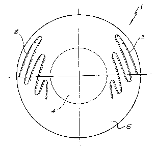
Figure 1: shows a front elevation of a lens having
waveforms thereon according to one embodiment, of
the invention.
Figure 2: shows a cross sectional view of the embodiment of
figure 1.
Figure 3: shows a front elevation of a lens having a
waveform thereon according to a preferred '
embodiment.
Figure 4: shows a cross sectional view of the embodiment of
f figure 3 .
Figure 5: shows a front elevational view of a lens having a
waveform thereon according to a preferred
embodiment.
Referring to figure 1 there is shown a front
elevational view of a lens 1 having waveforms 2 and 3
according to a preferred embodiment. The lens comprises an
optic zone 4 and-a radial planar zone 5 in which the
waveforms 2 and 3 are located. The angle of the waveforms
can vary both~in relation to each other or relative to the
vertical axis of the lens. It will be appreciated that the
waveforms may be inserted on the lens in a multiplicity of
configurations with the number of waves and the positioning
of the waves varying depending upon the particular result
r,. .
desired.
Figure 2 shows a cross sectional view of the lens of
figure 1 wherein the pitch of the waveforms 2 and 3 can be
readily seen. The depth of the wave troughs may vary from
wave to wave or from lens to lens according to requirements.
Referring to figure 3 there is shown an elevational
view of a lens 6 having a waveform configuration according
WO 92!22845 _ 6 _ PCT/AU92/00290
..~<.,,
to an alternative embodiment. Lens 6 as with lens 1 as
previously described, is divided into an optic zone 7 and a
radial planar zone 8 in which the waveform 9 is located.
The waveform shown travels around the periphery of the first
and second quadrants of the lens and is symmetrical about '
the vertical axis. In an alternative embodiment the lens
may also have incorporated in the planar zone.thin zones or
prism ballast 10 which assists in the locai~ing action caused
by the waveforms.
It will be appreciated that numerous permutations and
combinations of waveforms or combinations of waveforms and
thin zones or prisms may be incorporated in the lens
design. Figure 4 shows a cross sectional view of the
embodiment of figure 3.
Referring to figure 5 there is shown a front
elevational view of a lens having a waveform thereon
according to an alternative embodiment. Lens 11 comprises
an optic zone 12 and a radial planar zone 13 in which
waveform 14 is located. Optic zone 12 may be configured as
a bi-focal or multi-focal lens.
Waveform 14 is located in quadrants 1 and 2 of the lens
!l and travels generally in the direction of the vertical
axis. When a lens is configured with more than one
waveform, ideally the waveform is disposed on either side of
either the vertical or horizontal axis of the lens such that
symmetry is created about one or other of those axes. Where
there is a single waveform on the lens which may travel
between two quadrants of the lens, this may not necessarily
result in symmetry about an axis of the lens.
Although it has hitherto previously been known to
utilise patterns and/or grooves in the surface of a lens, it
has not previously been revealed exactly how such patterns
assist in orientation of the lens on the eye of a wearer.
When the waveform according to the present invention is
adopted, the forces which are generated between the waveform
and the eye lid of a wearer are transmitted from the tarsal
plate via the squeezing action of the obicularis oculi (an
onion like muscle which surrounds the orbit and maintains
lid tensions on the eye). The eye with lens in vivo will be
PCT/AU92/00290
WO 92/22845
subjected to both a backward, (that is towards the eye) and
. a downward force as the lids progress through their blinking
phase. The other major force (also mainly downwards), is
caused by the levator palpabrae superioris muscle which is
attached to the tarsal plate and causes the lids upward and
downward motions.
By harnessing both. of these forces and the natural
rigidity of the tarsal plate, the lens due ~ the '
corrugations in or on the surface may be orientated by
differential forces applied to the peaks (crests) and the
troughs of the waveform.
The crests, due to their relative altitude over the
troughs in the waveform will be subjected to a greater
backward and downward force than the troughs. This is due
to the inherent rigidity of the tarsal plate. The
springiness of this bony like structure will therefore
transfer forces in a vector downwards and backwards against
the peak and sides of the corrugations.
The corrugations themselves would not be so steep or
high as to cause the lid not to sweep the total lens. Thus,
the forces would be evenly distributed over the surface,of
the lens by the eye lid of a wearer.
By arranging the corrugations in a particular
configuration according to user requirements the inherent
2S forces can, in fact can be channelled downwards, backwards
and outwards (towards both nassal and tarsal canthi) and
therefore has a stabilising effect.
The ideal conceptual nature of tonic stabilisation is
to maximise the locating influences on the lens out as wide
as possible. This dramatically increases in vivo access
stability by placing maximum resistance to rotation at the
mqst advantageous areas of the lens. That is, the highest
resistance against rotation is located at the location on
the lens where the small force would tend to create unwanted
rotation.
Thus, by proper location of the waveforms the leverage
effect can be effectively placed. The troughs in the
waveform afford the lid an area of lesser resistance (that
is, to backward force) in order to vector forces to the
PCT/AU92/00290
WO 92/22845 ~ _ g _
sides and tops of the adjacent peaks or crests. Thus the
troughs are a crucial part of the stabilising effect without
actually having an active part in it in contrast to the
crests. The troughs therefore are considered to have a
passive roll in allowing a component of the backward forces '
to be distributed directly onto the crests. Not all of the
backward forces exerted by the eye lid will ,however, be
taken by the crests. A component of the backward force will
be taken by the crests with the size of the component force
being dictated by the slope angle of the crests. Although
grooves, holes and indentations forming lens surface design
patterns are known, even if these were machined and polished
smooth they would not have the accurate lens stabilisation
and orientation capability imparted by the waveforms as
described above. ,
One of the most significant advantages of the waveform
configuration is that ocular scratching and discomfort is
eliminated by careful polishing of the surface and in
particular the crest surfaces such that the contours are
extremely smooth. This form of finish is critical to the
prevention of ocular scratching and the elimination of clog
up with lipids, mucins and debris. Where grooves,
indentations or holes are used according to the prior art,
it is possible that lipids, mucins and debris may build up
in such grooves and holes thereby creating discomfort for
the wearer and other problems associated with deposition.
The present invention provides a particular surface
configuration eliminating discontinuities which led to
disadvantages in the prior art where patterns were formed on
a lens surface.
One disadvantage of the prior art methodology is in the
manufacture of the grooves, holes or indentations. Ablation
is the only accurate way currently available to mark contact
lens material to a predetermined depth. This process causes
ionisation of the polymer molecules and leaves a
characteristic fish scale appearance of scarred material on
the lens surface which is wholly undesirable.
The primary function of this system is again, to
harness to natural lid forces to create an external and
PCT/AU92/00290
WO 92/22845 ~ _ g _
deliberate physical effect on the lens in question. .
It will be recognised by persons skilled in the art
that numerous variations and modifications can be made to
the overall invention as broadly described herein without
departing from the spirit and scope of the invention.