Note : Les descriptions sont présentées dans la langue officielle dans laquelle elles ont été soumises.
^"."~j
~l ~
.~.~j M~THOD FOR CONTROLLING THE ATTITUDE OF ~ E AIMED
TOWARDS A CELESTIAL OBJECT AND A SATELLI~'E SUITABLE FOR
IMPLEMENTING IT
BACKGROUND OF THE INVENTION
5 The present invention concerns a method for aiming a satellite
with respect to a celestial or heavenly object (the sun or a
star for example) and a device suitable for implementing it.
Satellite in this case means any artificial object moving in
the solar system. This object may in particular be:
:
10 - in an orbit around the earth or any other planet in the
solar system,
- in an orbit around a satellite of any-planet in the solar
system,
- in a solar orbit, possibly a transfer orbit between two
15 planets.
As is known, satellites have, for the purpose of controlling
their orbit and attitude, sensors and actuators connected to
logic processor units within a system normally referred to as
the attitude and orbit control system. The logic processor
20 units are often integrated within an on~board compu~er, the
ackuators including ~or example thrusters (and/or magnetic
coils, and/or gears3 whilst the energy consumed on board is
provided by ~atteries, solar cells subjected to solar ~-~
radiation and/or propellants used for thrust propulsion in `
25 particular ~or orbit control.
As for the sensors, these are in practice of several types,
depending on the nature, size, brightness, etc of the heavenly
body (earth, sun or star) which they serve to detect. There
are currently single-axis or dual-axis sensors.
30 Single-axis sensor means in general an appliance providing an
angular coordinate of the directio~ of the heavenly body aimed
at in a frame of re~fere.nce peculiar to the sensor. In
practice an axis of sight and a sensing axis are defined ~or
.
~....
- ..
` 2111602
this sensor, and this angular coordinate is for example the
angle made by the axis of sight of the sensor to the
projection of the direction of the heavenly body aimed at onto
the plane containing the axis of sight perpendicular to the
~; 5 sensing axis~
A dual-axis sensor means here an appliance supplying two
angular coordinates of the direction of the heavenly body
aimed at in a frame of re~erence related to the sensor (which
determines this direction completely). This appliance
therefore has the function of two single-axis sensors with
identical axes of sight and separate sensing axes, generally
orthogonal. For detecting the sun, such a dual-axis sensor is
in fact normally formed by associating two such single-axis
sensors.
In fact a satellite may be caused to adopt several attitudes
during its life after being released ~rom its launch vehicle.
Thus, fox example, the nominal attitude of a satellite of the
triple-axis stabilised type moving on a circular terrestrial
orbit consists of having a Z axis t known as the yaw axis,
pointing towards the earth, a Y axis known as the pitch axis,
perpendicular to the plane of the orbit, and an X axis known
as the roll axis, perpendicular to the Z and Y axes and having -
the same direction as the instantaneous linear velocity of the
satellite on its orbit, the direction of the Y axis being such ~`~
that the frame of xeference (X, Y, Z) is positive. Such a
nominal attitude is controlled by means of a terrestrial
sensor, either alone or combined with solar sensors or a
stellar sensor.
~ .
Other types of attitude may be envisaged, notably just before
a satellite is put into its operational orbit, or after a
serious failure of any type af~ecting in particular the
attitude and orbit control system.
.
...
" 3 2111602
It is normal in such cases to attempt to put the satellite
into a so-called sun-aimed attitude in which it is in slow
rotation about an axis pointing towards the sun, chosen so as
to be close to a principal inertia axis and such that the
5 satellite solar panels are illuminated. This enables the
satellite to await subsequent commands, whilst ensuring its
safety, that is to say:
- ensuring the recharging of the batteries with which the
satellite is equipped,
lO - powering the various items of equipment required by the
satelliteo sensor, computer, heaters, remote control and
telemetry, in particular,
- ensuring illumination of the satellita by the sun so that
` the thermal configuration of the satellite is homogeneous and
15 maintains the equipment within the permitted temperature
range.
.
Conventionally, this attitude control mode is referred to as
the sun acquisition mode and is based on a sequencing of the
~ollowing type given by way o~ example:
~:
20 - seeking the sun by rotating the satellite about one axis ``~
~for example the roll axis), so that the field of view of at
least one solar sensor encounters the sun,
"..
- rotating the satellite about one axis (for example the pitch
axis) so as to bring the direction o~ the sun towards the
25 desired direction,
- rotating the satellite about the direction of the sun, and
controlling this direction so that it becomes identical with
the desired direction t~or example the roll axis).
The satellite thus being in a sun-aimed attitude, the
~ ,
r
` 4 ~ 6 0 2
requirements of the mission generally require it to come (or
return) to its nominal attitude, that is in practice for it
then to be aimed (or re-aimed) towards the earth (or a star).
The method of seeking the earth or star which is
5 conventionally used, in such an sarth acquisition mode or star
acquisition mode, consists, during the seeking stage, of
putting the satellite into slow rotation about an axis aimed
towards the sun, this axis being chosen so that the field of
view of the earth (or star) sensor necessarily encounters the
10 éarth (or star).
:
In some cases, when it is not possible to seek the earth
directly, a reference star is initially sought, the Pole Star
~or example: once the star has been found as described above,
the satellite is, from the measurements of the star sensor,
15 controlled with respect to rotation so as to bring the field
of view of the earth sensor facing the earth: this is then
referred to as acquisition of the earth via the star.
The rotation axis pointed towards the sun during the seeking
of the earth or star forms, with the axis of sight of the
20 earth or star sensor, an angle at least approximately equal to
the sun-satellite-earth angl~ or sun-satellite-star angle.
This axis may be khe direction which the sun should have in ~`
the frame of reference related to the satellite once the `
latter is in its attitude pointed towards the earth or star. ;~
. ~
25 These different attitude control modes therefore require the
direction of the sun or star in question to be determined for
the purpose of taking it into account in the control loops
using the control law corresponding to the current stage of
the attitude control mode: in particular in the last phase of
30 the sun acquisition mode, in the first phase of the earth or
star acquisition modes and in the last phase of the
acquisition of the earth via a star.
Amongst the documents which relate to such a change in nominal
:: 5 2 1 ~ 16 ~ 2
attitude, a~ter an intermediate change into a sun-aimed
attitude, can be cited the patents FR-2.407.860
(MESSERSCHMITT-BOLKOW-BLOHM), EP-0.338.687 (BRITISH
AEROSPACE), US-5.080.307 (HUGHES AIRCRAFT) and FR-2.649.809
(MESSERSCHMITT-BOLKOW-BLOHM).
In the first three patents, the direction of the sun is
determined from the measurement of two single-axis solar
sensors whose sensing axes are perpendicular, or from a twin-
axis solar sensor.
:: :
Likewise, in the patent EP-0~338.687, the direction o~ the
star is computed from the measurement of two single-axis
stellar sensors whose sensing axes are perpendicular, or from
a twin-axis stellar sensor.
The computation is carried out by determining the three
coordinates o~ the unit vector o~ the instantaneous direction
of the sun or star in the frame of reference of the sensor ~ ;
from two angular measurements defining the orientation of this
direction in the frame of re~erence. `
.
Control is effected by applyin~ demands of the type~
.
U=-Kd*~-C*S~c]-Kp*~S~c A SR]
where:
U = demand signal to be applied as determined by the ~
control law ::
S~c = unit vector of the instantaneous direction of the ~:
heavenly body in question (sun or star) calculated
from the angular measurements oE the sensors
SR = unit vector of the reference direction of the
heavenly body in question
~ A ~ V ~ :
`~:
~`` 6 21~1~02
~ ~ = measured velocity vector
: :
C = velocity of rotation demanded about the direction
SR
Kd - velocity regulation gain
5 Xp = position regulation gain
:~
`~ A = vector product (or, in English, cross product).
; During the sun, earth or star acquisition modes, the velocity
o~ the satellite about its three axes is measured (by means o~
gyrometers, for example) and used in the attitude control ~
laws, solely ~or the purpose of damping the positional control ~:
or carrying out the ~elocity control.
~ :
An earth-seeking mode using a single solar sensor is described
in the patent FR-2.649.809. This patent proposes a method in
which the direction of the sun is not completely determined.
The control law is based on the ~act that the rotation of the
satellite causes coupling between the errors in attitude
according to the measurement axis and according to the non-
measurement axis. Thus, when the sin~le-axis solar sensor
detects an error, the control law generates a command suitable
~or cancelling out this error according to the measurement
axis, whilst the non-measurable error on the other axis is
eli~inated by coupling.
: ' ':
The control law used is o~ the type:
,
U--Kd*[~-C*S~]~Kp*[SRAeM+(S~*sRT)eM-eM]*L(N,r-Nby)
: . .
where:
U = demand to be applied
SR = unit vector o~ the referenc~ direction of the sun
~-
"`; . 7 2 ~ 0 2
SRT = transposed unit vector of the re~erence direction of
the sun
~ = measured velocity vector
¦ C = rotation velocity demanded
5 Kd -- velocity regulation gain ~ .
: Kp - position regulation gain
eM = measurement axis vector
N~ = solar sensor measurement
~: Nby = correction of the solar sensor measurement
:
10 ~ = identity matrix : :
;~ L = limitation ~actor
A = vector product tor, in English, cross product). :-:~
;~It will be noted that this command includes a term relating to
velocity control according to three axes and a term relating
to positional control according to two axes, namely the
measurement axis a~d an axis perpendicular to this measurement
axis and to the reference direction of the sun, referred to as ~
the non-measurable component axis. :~:
This method has the following drawbacks:
- complexity o~ the control laws, which are very differen~
from the conventional laws of the earth and sun acquisition .
modes, . ~
. - poor acauracy of aiming about the non-measurable component .. :
axis since this axis is controlled passi~ely by coupling and
the error in attitude about this axis is never measured or
. determined,
.
~ difficulty in using this control law to generate thruster
commands on the aforesaid two axes since that requires:
. either a complicated logic for generating impulses of
different durations on the different thrusters: the
impulse modulator conventionally used on known satellites
!. ,.
8 21~ 02
is then not applicable,
:~
-~ . or using thrusters ha~ing specific orientations suitable
for producing torques on both axes, which de-optimises
the system of attitude control of the satellite by
thrusters since the directions of these thrusters are
then imposed by the datum of these two axes.
An earth-seeking mode using a single solar sensor based on
coupling between axes due to the rotation is also described in
the document: "The attitude and orbit control of the EUTELSAT
II spacècraft" 6.11 page 95, Symposium on Automatic Control
in Space - IFAC - 17-21/7/1989. This document proposes an
earth-seeking mode in which the reference direction of the
rotation vector of the satellite during the earth seeking is
chosen so that it forms, to the direction of the sun, an angle
equal to the earth-satellite-sun angle and so that its
component which cannot be measured is zero. This article
deals with the pitch component, which amounts to saying that
the sun is maintained in the XZ plane of the satellite
throughout the earth-seeking phase and that the ~inal attitude
at th~ time o~ sensing the earth has a yaw angular di~ference.
During the earth seeking, only veloci~y control about the
direction SR is suggested, so that the control law used by
this method is probably of the type:
U = -Kd*[~-C*SR]
25 where:
.~
~, U - demand to be applied
SR = unit vector o~ the reference direction of the sun
= velocity vector measured
~ - velocity o~ rotation about SR
; 30 Kd = velocity regulation gain
, .
This method has the following drawbacks:
~, ~`
:: `::`
9 2 ~ 0 2
- the necessity for two additional stages: pitch rotation to
bring the sun facing the sensor used, and then yaw rotation to
cancel out the yaw error due to the particular choice of the
reference direction of the sun,
- the poor accuracy of the aiming, which deteriorates over
time because of drift in the gyrometers and because the ~.
control law does not includa the positional control term.
This poor aiming accuracy: :
,
: . prevents itsapplication to the sun acquisition mode, the
long duration of which (typically several hours) would,
with this type of law, result in latent aiming errors, ::
. prevents its application to the star acquisition method,
which requires great aiming accuracy because of the need .
to recognise the star,
I5 . the risk, in some cases, of resulting in ~ailures of the
earth acquisition.
on the other hand, the present invention relates to a method
for aiming the satelli~e..-towards a heavenly body such as the
sun or a star:
- which is applicable to any triple-axis stabilised satellite
whatever the arrangement of its thrusters (unlike the patent
FR-2.649.809),
- which does not call into question the logics conventionally
used for the sun, earth or star acquisition modes (unlike the
patent FR-2.649.809),
- which uses the measurement of a single solar or stellar
sensor with a single measurement axis (unlike the patents FR-
2.407.860, EP-0.338.687 and US-5.080.307) but in combination
with other available measurements,
~ '
.
` lo 2111~2
- which can easily be programmed in the on-board computer,
- the aiming accuracy of which is optimum because of a
positional control carried out aotively and continuously, by
comparing the calculated direction of the heavenly body with
the direction aimed at or reference direction.
SUMMARY OF THE INVENTION
To this end the invention proposes a method of controlling the
attitude of a satellite according to which the direction of a
predetermined celestial object is defined in a frame of
reference related to the satellite, the instantaneous angular
velocity vector of ~he satellite is detected and, by means of
an actuating assembly, torques are applied to the satellite
which are defined by a control law so as to rotate ~he
satellite about this direction whilst orienting an aiming axis
related to the satellite in this direction, characterised in
that this direction of the predetermined celestial object is
defined in the frame of reference related to the satellite by
a first quantity representing a first angle measured between
an axis of sight and the projection of this direction onto a
first reference plane containing this axis o~ sight and by a
second quantity representing a second angle defined by this
axis of sight and the projection o~ this direction onto a
second reference plane containing this axis of sight, this
second angle being calculated from this first angle and ~rom
the instantaneous angular velocity vector of the satellite.
Compared with the conventional methods known at the present
time, this method maXes it possible to save on one axis for
measuring the heavenly body aimed at ~namely the use of a
single-axis sensor instead of a twin-axis sensor or saving on
one single-axis sensor), its redundancy and, possibly, sensor
control electronics, and therefore to reduce the weight and
cost of the satellite attitude control system; all this
without changing the structure of the sun, earth or star ~:~
aoquisition modes.
:
.. ... ..
``` 11 21~02
This method can al~o be appli~d to a satellite for dealing
with a failure of some of its sensors. In such case, the
satellite may already be in orbit.
The calculation method is based on the relationship between
5 the direction of the heavenly body aimed at and its change in
a frame of reference related to the satellite, the single
; measurement of the sensor and its change and the angular
velocity measurements.
According to preferred characteristics of this method:
~: :
- this axis of sight belongs to a sensor with at least one
sensing axis, the first reference plane being defined as being
perpendicular to the sensing axis,
- the second reference plane is perpendicular to the first
reference plane and is defined as containing the axis of sight
and sensinq axi5,
- the sensor is a single-axis sensor,
- the sensor is a twin-axis sensor, a single output of which
is used,
- the first and second quantities representing the first and
second angles are the tangents of these angles,
- the control law is of the type:
U=-Kd*~-c*sslc]-Kp*~sslc ~ SR]
' where: ~
_ '.:
U = demand to be applied to the torque generator
Ss~c = unit vector of the instantaneous direction of the
celestial object
SR = unit vector of the aiming axis forming the rotation
reference axis
. '' ~'~
;'
`;``` 12 ~1116~2
= measured velocity vector
C = rotation velocity demanded about SR
Kd = velocity regulation gain
Kp = position regulation gain
5 A = vector product (or, in English, cross product)
- the celestial object is the sun,
the aiming axis is an axis which is at least approximately
close to an inertia axis of the satellite, chosen so as to
obtain continuous illumination of a solar generator installed
on the satellite, by virtue of which the satellite is in a
sun-aimed mode, ~-
- the satellite has another sensor with a second axis of
sight, suitable for detecting another predetermined celestial
object, and the aiming axis is chosen so as to form, with this
second axis of sight, an angle at least approximately equal to
the (sun) - satellite - ~or other celestial object) an~le,
this other celestial object is a star, by ~irtue of which
the satellite is in star acquisition mode,
` - this other celestial o~ject is the earth, by virtue of which
the satellite is in earth acquisition mod~,
- the celestial object i5 a star, ~
:~. ,,'
- the satellite also has a terrestrial sensor with a second
axis of sight, and the aiming axis is chosen so as to form,
with this second axis of sight, an angle at least
approximately equal to the star-satellite-earth angle, hy
virtue of which the satellite is in the mode for the
acquisition of the earth from a star.
The invention also proposes a satellite having a body, a
sensor with an axis of sight suitable for detecting a ;
,~
f~ .
13 2 i l~ 6 ~ 2
predetermined celestial object and supplying a first quantity
representing a first angle measured between the axis of sight
and the projection of the instantaneous direction o~ the
celestial object onto a ~irst reference plane containing this
axis of sight, an actuating unit, an at~itude control unit
suitable for generating, from this Lirst quantity and a second
quantity representing an angle defined by the axis of sight
and the projection of this instantaneous direction of the
zelestial object onto a second reference plane containing this
axis of sight, separate from the first reference plane,
signals suitable for applying to the satellite, through the .
actuating unit, torques suitable for rotating the satellite
about this direction and orienting an aiming axis in this
direction, and a unit for measuring the instantaneous rotation
velocity of the satellite, characterised in that this second
representative quantity is applied to the attitude control
unit by a preliminary processing unit suitable ~or calculating
this second quantity from the first quantity and from the :
output signal of the instantaneous rotation velocity
measuremen~ unit.
According to pre~erred characteristics of this satellite:
- this sensor is a sensor with a single sensing axis, the
~irst reference plane being perpendicular to this sensing
axis, and the second réferenc~ plane containing this sensing
axis,
- the sensor is a solar sensor,
- the satellite also has a stellar sensor,
- the satellite also has a terrestrial sensor,
- the sensor is a stellar sensor,
:~
- the actuating unit inclucles thrusters,
~ `
~`" ` 21~602
14
- the uni~ for measuring the instantaneous rotation velocity
of the satellite includes gyrometers.
BRIEF DESCRIPTION OF THE DRAWINGS
Objects, characteristics and advantages of the invention will
emerge from the following description, given by way of non-
limitative example, with reference to the accompanying
drawings in which:
:~
- Figure 1 is a diagram of a single-axis sensor,
- Figure 2 is a diagrammatic view in perspective of a
satellite according to the in~ention,
:
- Figure 3 is a functional diagram of an aiming device
according to the invention,
- Figure 4 is a perspective view of the satellite of Figure 2
in the earth seeking phase, and
- Figure 5 is a diagrammatic view of this satellite after
sensinq of the earth.
. DESCRIPTION OF THE PREFERRED EMBODIMENT :.
A single-axis sensor as shown diagrammatically under the
reference numeral 1 in Figure 1 is in practice a slot
extending along an axis Ys referred to as the sensing axis,
perpendicular to an axis Xs referred to as the non-measurement
axis, whilst the axis Zs perpendicular to the plane XsYs of ~-
the sensor is referred to as the optical axis or axis of -
sight, intended to be oriented sufficiently close to the
celestial object to be detected for the latter to come within
the field of view of the sensor.
..
What has just been stated applies particularly where the
sensor is a solar sensor. A stellar sensor generally consists
of a charge transfer detector matrix (CCD matrix) onto which
an image of the star is projected. The measurement of the
sensor in fact consists of two coordinates of the pixel or
::
~.,
; 15 2111~02
pixels illuminated by the star. This stellar sensor,
generally with dual axes, is able to supply only a single-axis
indication if a measurement processing fault results in the
¦ provision of a single coordinate instead o~ two. In such
5 case, the invention can be applied.
If S is the direction of this celestial object, the sensor 1
provides a measurement signal representing the angle a between
the axis of sight and the projection of this direction in a
reference plane passing through the axis of sight and
lO perpendicular to the sensing axis.
It is important to note that the angle B between the axis of
sight and the projection of S in a second reference plane
defined by the axis of sight and the sensing axis is on the
other hand not measured.
The atti~ude drifts which the satellite may undergo about the
axes Xs, Ys and Zs which, for the sensor, are roll, pitch and
yaw axes, are designated by ~, ~ and ~.
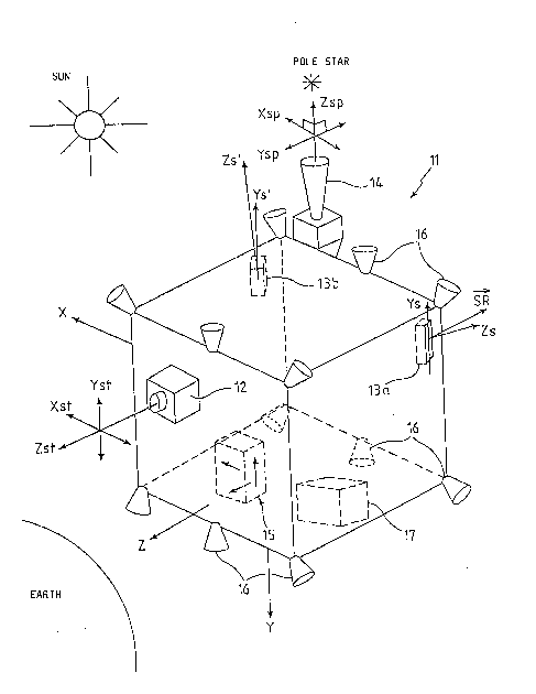
Figure 2 shows diagrammatically the body 11 of a triple-axis
stabilised satellite according to the invention, including in
2b addition, in a con~entional manner, a solar generator with one
or more panels (not shown).
In the case considered here of a given earth orbit, preferably ~ -
geos~nchronous, of low inclination (typically less than 10)
the three axes along which it is sought to stabilise this ;~
satellite ~that is to say its body) in nominal attitude are,
respectively, an axis directed towards the earth, usually
termed Z and refexred to as the yaw axis, an axis
perpendicular to the plane of the orbit and directed towards
the south, termed Y and referred to as the pitch axis, and an
X axis forming, with the pitch and yaw axes, a positive
orthonormal axis system (X, Y, Z), and referred to as the roll
axis. In practice, when the orbit is circular, this roll axis
. `
` é ~ :
.,.,.",...............
:`` 16 2 ~ 0 2
is tangent to the orbit and preferably has the same direction
as the velocity at which the satellite moves on the orbit.
Generally the solar generator extends parallel to the pitch
axis.
5 The body 11 of the satellite has an attitude and orbit control
system comprising:
::~
: - a terrestrial deteation system 12, here formed by a single
twin-axis detector, having an optical axis Zst parallel or
; close to the Z axis and two measurement axes (or sensing axes)
Xst and Yst (in practice orthogonal) transverse to the optical
axis, advantageously close or even parallel to the X and Y
axes of the satellite respectively (the field of view is for
example + 14 around the axis Ys and + 5 around the axis Xs),
- the solar detection system including a plurality of singla-
axis solar.sensors having axes of sight of different
orientations: two sensors 13a and 13b are shown here, with
axes o~ sight Zs and Zs' respectively oriented in the plane XZ
at least approximately a~ 45 from the axes -X and -Z on the .:
one hand and X and -~ on the other hand, and having sensing :
axes at least approximately parallel to Y,
. ' '.' .
- an optional stellar detection system 1~, here formed by a
twin-axis detector, having an optical axis Zsp pointed towards
the north so as to be able to detect the Pole Star (as a :
reminder, the Pole Star is very close to the north) and two ~ .
measurement axes Xsp and Ysp parallel to X and Z; this stellar :~
' detection system 14 is in practice offset from the Y axis by a .
sufficient distance to prevent the solar generator encroaching -~
appreciably into its field o view;
- an ang~lar velocity detection unit 15, for example
gyrometers, for measuring the angular velocities of the
satellite about three axis preferably parallel to the X, Y and
. : .
::
~ ~ ~,. ~.,., ,.~`,''`,', . .~::,~,~: ~ ,j ::,'
-~
~: 17 ~ 6 ~ 2
Z axes,
- a~ actuating unit, in this case formed by thrusters 16 at
least four in number (in this case six), for generating
positive or negative control torques about the X, Y and Z
: 5 axes, and
- an analogue or digital processing unit 17, for processing
the measurements supplied by the detection systems and, by
means of control laws which are per se conventional, in the
:; nominal attitude control reg:ime or in reacquisition mode,
~: 10 co~mands intendad ~or the actuating unit (through filters,
limiters and modulators).
: ':
The process of the invention i9 described below with regard to
the functicnal diagram in Figure 3, involving any one of the ~
singl~-axis solar sensors (chosen according to the desired .. :
direction o~ rotation) and the angular velocity detection unit
15. In the example in question, aiming is effected by means
of the solar sensor 13a.
The various quantities which will be used in the iterative
calculation defined below, have the followin~ definitions: .
. '.~
.20 sx~cl S~c
Sz~c : components of the unit vector of the .~.
direction of the heavenly body in
satellite axes,
SX, SY, SZ : components of the unit vector of the :;-
direction of the heavenly body in sensor :~
' axes at the previous moment,
SXI, SY', SZ' : components of the unit vector o~ the
direction of the heavenly body in sensor
axes at the present moment,
30 ~ : angle between the axis Zs and the
projection of the direction of the
heavenly body in the plane Xs, Zs in the
' :
.
: .`` 18 2111602
.sensor frame of re~erence,
B : angle between the axis Zs and the
projection of the direction of the
heavenly body in the plane Yszs in the
~: 5 s~nsor ~rame of reference
: tan~' = SX'/SZ 7 current measurement of ~ by the sensor
: tan~ = SX/S~ : previous measurement of ~ by the sensor
used
tanB' = SY'/SZ' : current estimation of B
10 (tan*')f current filtered value of tanB
tanB) f : previous filtered value of tanB ~::
: roll, pitch and yaw micro-rotations
: between the sensor frames of reference at
the previous and current moments ::.
15 Dt : duration of the calculation cycle
~xs= Dt ' ~Yg Dt ' ~5 D~
roll, pitch and yaw velocity in sensor ~
axes ~;
~c' ~y~o' .... ~,
20 ~z~c : roll, pitch and yaw velocities measured by ~
satellite axis :.
M : matrix for converting between the ~.
satellite axes and sensor axes .
: inverse matrix of the matrix M
It should first of all be noted that there is a change from
the heavenly body according to sensor axes, between the -~
previous and current moments, by means of the matrix equation~
~sxl f ~ 1 fs~
sY = ~ sY' .:
sz ~ ~ 1 s~',
.~, .
30 The variation ~ in the tangent of the measured anqle ~ is : ;~
equal to: ~ - tana' - tan~, that is to say:
I
~5}~
: `
19 2 ~ 0 2
~=tan~ tan~=~SX/ SX= SX~ S~-~*Sy/+~*
SZI SZ SZI SZ~*S~-~*SX~
or again:
*tan~*tan@/_- tana~*tan~*~ - tan~
1-tan~*~-tana/*~
5 The est.imation of the non-measured angular component B' of the
direction of the heavenly body in the sensor frame of
reference is effected:
by cal~ulating the instantaneous velocities of rotation in ;~
the sensor frame of reference according to the change of frame
10 of reference formula:
~xsl ~)x~c~
~i)yS = M I ~ys/C : ~ ~
,~)Z5 l~ZS/C, . ` . '^
- whence tanB' is calculated by the equation:
~yS~tan*tanal*~yS*
~z9+~xg*~an~
' ~`~'`' ~ `' '
Advantageously a filtering of tanB' is carried out in order to
eliminate the effect of the cyclic determination of this
tangent. This filterinq is for example a first order
20 filtering of the type~
~tanB')r - a(tanB)f ~ (l-a)tanB' ~`
, where the subscript f corresponds to the filtered values and
where a is a constant. ~-
Finally, there is a progression, in a ~nown manner, from these
25 tangents to the components of the unit vector of the direction
of the heavenly body in the sensor frame of reference
according to the e~uations:
~ "~ ' .ul
t~
~ . 20 2111~2
I_ tan~l
SX-- - -
~l+tan2a,~ 2 p j
.
_ tan~ :
~/l+tan2~tan2~/
~ ~ 5Z/~
tan2a/+tall,2~1
~:; and then by change o~ ~rame of reference these components are
5 determined in the satellite frame of re~erence: :~
~ = M ISYI
~ sz
. ~
The attitude control proper is then obtained by means of a ::
lO conventional law, *or example the one already presented above
: in the prea~ble:
U=-~d*~-c*s~c~-Kp*~s~c A SR]
where SR has the same meàn~ng as before.
In Figure 3 can thus be seen the sensor whose field of view ~
15 contains the satellite-heavenly body direction (in this case ~ :
the single-axis sensor 13a), the angular velocity detection.
unit 15 Pormied by gyromieters, the processing unit 17 and the
actuating means 16.
The processing unit 17 includes a control unit 20, ~:~
20 conventional in itself, suitable for supplying attitude
control signals U fromi two quantities characteristic of the
angular orientation of the satellite-heavenly body direction : :
(in this case the tangents of the instantaneous angles ~' and
B').
25 According to the invention one of these quantities is derived,
not directly and solely from the output of an angular position
,~,,",,.,.,, .. ,.,.,.,,.,.. ,.,.,,.. .. , .,, ,. ~
;~ 21 21 11~2
sensor, but from the instantaneous angular velocity of the
satellite in the frame of reference (X, Y, Z) related to it.
The processing unit 17 includes for this purpose a preliminary
processing unit 21 suitable for calculating as indicated
abova, from the single quantity tan~ supplied by the sensor
13a and the instantaneous angular velocity ~, the other
quantity tan~ required by the control unit.
The satellite 11 in earth seeking phase can be seen in Figure
4. The satellite 11 is rotating about the axis SR pointed ;~
towards the sun. This rotation brings the axis of sight of
; the terrestrial sensor (which is identical with the yaw axis
of the satellite~ facing the earth, thus enabling the latter
to be detected. This situation is shown diagrammatically in ~-
Figure 5.
It goes without saying that the above description has been put
forward only by way of non-limitative example and that many
variants could be proposed by a person skilled in the art
without departing from the scope of the invention. Thus, for
example, the stellar sansor could be omitted: a single-axis
solar sensor with an axis of sight approximately directed
along Z could then be added in order to supplement the field
in which it is possible, at any time, to search for the sun. ~`
Likewise the process of the invention can be applied without
any problem:
- to the case of a satellite provided with at least one twin-
axis solar or stellar sensor formed by two coupled single-axis
sensors, one o~ which happened to fail,
- to the case of a satellite provided with at least one twin-
axis stellar sensor, the measurements of which along one of
the axes is unavailable because of a failure.