Sélection de la langue

Search

Sommaire du brevet 2112296 

Énoncé de désistement de responsabilité concernant l'information provenant de tiers

Une partie des informations de ce site Web a été fournie par des sources externes. Le gouvernement du Canada n'assume aucune responsabilité concernant la précision, l'actualité ou la fiabilité des informations fournies par les sources externes. Les utilisateurs qui désirent employer cette information devraient consulter directement la source des informations. Le contenu fourni par les sources externes n'est pas assujetti aux exigences sur les langues officielles, la protection des renseignements personnels et l'accessibilité.

Disponibilité de l'Abrégé et des Revendications

L'apparition de différences dans le texte et l'image des Revendications et de l'Abrégé dépend du moment auquel le document est publié. Les textes des Revendications et de l'Abrégé sont affichés :

  • lorsque la demande peut être examinée par le public;
  • lorsque le brevet est émis (délivrance).
(12) Demande de brevet: (11) CA 2112296
(54) Titre français: METHODE DE CONSTRUCTION D'ECHAFAUDAGE, ET NOTAMMENT MOYENS DE RACCORDEMENT DE DEUX OU PLUSIEURS DE SES POTEAUX EN POSITION VERTICALE
(54) Titre anglais: SCAFFOLDING CONSTRUCTION, IN PARTICULAR MEANS FOR JOINING TWO OR MORE OF ITS POSTS IN VERTICAL POSITION
Statut: Réputée abandonnée et au-delà du délai pour le rétablissement - en attente de la réponse à l’avis de communication rejetée
Données bibliographiques
(51) Classification internationale des brevets (CIB):
  • E04G 07/20 (2006.01)
  • E04G 07/30 (2006.01)
(72) Inventeurs :
  • VAN HELMOND, JOHANNES H. M.
  • VAN HELMOND, JOHANNES HUBERTUS MARIA
(73) Titulaires :
  • SGB HOLDINGS LTD.
(71) Demandeurs :
  • SGB HOLDINGS LTD.
(74) Agent: SWABEY OGILVY RENAULT
(74) Co-agent:
(45) Délivré:
(22) Date de dépôt: 1993-12-23
(41) Mise à la disponibilité du public: 1994-06-29
Licence disponible: S.O.
Cédé au domaine public: S.O.
(25) Langue des documents déposés: Anglais

Traité de coopération en matière de brevets (PCT): Non

(30) Données de priorité de la demande:
Numéro de la demande Pays / territoire Date
9202269 (Pays-Bas (Royaume des)) 1992-12-28

Abrégés

Abrégé anglais


A B S T R A C T
A scaffolding construction, in particular comprising
H-shaped frames. The posts (1) of a frame are provided at
the one end (4) with a bushing (5), of which the inner
diameter is larger than the outer diameter of the post (1).
The bushing (5) is provided with a recess (7) and with a
staggered groove (8) lying opposite to it. The other end of
a post (1) is provided with a pin (14) which can be fit-
tingly received in the groove (8) and in the upper end of a
post (8). In the horizontal position of the posts, its pins
are inserted in the groove (8) via the recesses (7). During
the angular rotation which the post (1) carries out while
being swung into its vertical position, the pins (14) are
guided by the grooves (8), and the posts by the recesses
(7), so that so that the pins come to rest in the posts.
Figure 1.

Revendications

Note : Les revendications sont présentées dans la langue officielle dans laquelle elles ont été soumises.


The embodiments of the invention in which an exclusive
property or privilege is claimed are defined as follows:
1. A scaffolding construction, in particular means which
allow two or more posts thereof to be joined together in a
vertical position, characterized by a post (1) at the one
end (4), which end forms the upper end of the post in the
assembled construction, being provided with a bushing (5),
of which the inner diameter (DB) is larger than the outer
diameter (DS) of a post (1) and of which a portion (6)
protudes beyond the end (10) of the post, which protuding
end is provided with a recess (7), open at the top, which
extends across part of the circumference of the bushing (5),
and with a groove (8) in the wall portion of the bushing
opposite to the recess (7), such that the groove (8), as
viewed in the longitudinal direction of the post, is stagge-
red relative to the recess (7) and the outermost end (11)
lies in between the ends of the recess (7) lying opposite,
while the lower end of a post (1) is provided with a pin
(14) which can be received fittingly in the groove (8) and
in a portion of the upper end of a post (1), in which the
groove (8) in the bushing (5) moves so far towards the end
(10) of the post (1) that the pin (14) brought into the
groove -of a post (1), in horizontal position, which is
supported by the recess (7)- is guided by the vertical walls
of the groove (8) during part of the angular rotation made
by the post (1) when it is swung into the vertical position,
while a portion of the post is supported by the lower edge
(12) of the recess (7).
2. A scaffolding construction according to Claim 1, cha-
racterized by the pin (14), joined to the end of a post (1),
having a square cross-section.
3. A scaffolding construction according to Claim 1 or 2,
characterized by the inner diameter (DB) of the bushing (5)
being larger than the outer diameter of the post (1), and
that the recess (7) extends across less than half the cir-
cumference and the width (BU) of the recess (7) being suffi-
cient for letting a post (7) pass.

4. A scaffolding construction according to any of the
preceding Claims, characterized by the groove (8) extending
till the other end (9) of the bushing (5), and that the
lower edge of the bushing (5) is welded to the post (1) or
is fixed to it in any other way.
5. A scaffolding construction according to any of the
preceding Claims, characterized by the use of a locking pin,
which can be inserted in bores (17, 18), which lie in line,
in the pin (14) joined to a post (1) and the portion of the
post (1) in which the pin (14) can be received.
6. A scaffolding construction according to any of the
preceding Claims, characterized by two parallel and spaced
posts (1) being joined together by at least one cross beam
(2) lying across the posts, such that a substantially
H-shaped frame is obtained.

Description

Note : Les descriptions sont présentées dans la langue officielle dans laquelle elles ont été soumises.

- 1 2112296 :
SCAFFOLDING CoN-s-TRucTI-oN~ IN PARTIC_L~ _E_NS FOB
JOINING TWO OR MORE OF ITS POSTS IN VERTICAL POSITION
The invention relates to a scaffolding construction,
and in particular, to the means which allow two or more
posts thereof to be joined together in a vertical position.
In the known constructions, said means are, for exam-
ple, formed through the provision of a member at the lower
end of a post, that can be received in the upper end of the
underlying post.
That is, a post must first be placed in a vertical
position above a preceding post. Because there are no lif-
ting means available in most cases, this forms a heavy
physical strain on those who build up the scaffolding. This ~;
is also caused through the scaffolding elements usually
being formed of steel because of costs and strength, and
which therefore are heavy.
Furthermore, in most cases the position in the known
constructions at which the posts are joined together, will ~ -
be located at the level of a platform, since otherwise the
- 20 next post cannot, or can only with difficulty, be brought
into a vertical position-above the preceding post. That is
to say, as long as a following post has not been placed on
the preceding one, the platform cannot be provided with
rests. This makes the assembly of the scaffolding less safe. -
The purpose of the invention is the removal of these
objections, and to that end, it provides a post at one end,
which end forms the upper end of the post in the assembled
construction, provided with a bushing, of which the inner ~
diameter is larger than the outer diameter of a post and of -
30 which a portion protudes beyond the end of the post, which -
protuding end is provided with a recess open at the top, ;~
which extends along a part of the circumference of the ~ -
bushing, and with a groove in the wall portion of the bus~
hing lying opposite the recess, such that the groove, as
viewed in the longitudinal-direction of the post, is stagge-
red relative to the recess and the outermost end lies be-
tween the ends of the recess lying opposite, while the lower
end of a post is provided with a pin which can be fittingly
received in the groove and in a portion of the upper end of
`.~ ' ~ '''.''. ' ..

2 21122 9 ~
a post, whereby the groove in the bushing proceeds so far
towards the end of the post, that the pin mounted in the
groove, of a horizontally positioned post supported by the
recess, is guided by the vertical walls of the groove during
part of the angular rotation which the post carries out
during its swinging into the vertical position, while a
portion of the post is supported by the lower edge of the
recess.
During assembly, a post is brought into the horizontal
position and moved in this direction, such that its pin
falls into the groove and can come to rest in the recess.
Following this, the post can be swung into the vertical
position. Due to the weight of the post, its pin will lower
automatically and move through the groove towards the upper
end of the underlying post, and finally be received in
there.
Thus, a kind of hinge is formed between both posts, but
without a fixed joint being present between the posts. Since
the post to be assembled first can be brought into the
horizontal position in the bushing of the preceding post,
the bushing can be located at some distance above a plat-
form. It is therefore -possible to provide the platform
directly with rests, so that the placing of the next post
can be conducted safely.
For limiting the width of the groove, it can be provi-
ded that the pin connected to the end of a post possess a
square cross-section. Then, the width of the groove is
required to be only slightly larger than the size of a side
of the square. The wall thickness of the bushing, and there-
fore its production cost, can therefore be kept as low as
possible. '
In using a pin with a square cross-section, it can be
received more easily in a preceding post with a circular
cross-section, than in the case in which the pin possess a
circular cross-section.
For optimum guidance of a post during its being swung
from the horizontal position to the vertical position, the
inner diameter of the bushing can be provided to be larger
than the outer diameter of the post, and that -the recess

~ 3 2112296 ::
extends over less than half the circumference, and the width
of the recess is sufficient for letting a post pass.
The post swinging upwardly therefore experiences a
better support in the direction perpendicular to the plane
in which the post is being moved.
Furthermore, it is achieved that the bushing is weake-
ned as little as possible where the recess and the groove
lie opposite to each other. It is also because of this that
the wall thicknass of the bushing can be kept limited.
The manufacturing of the bushing can be simplified
because the groove extends till the other end of the bus-
hing. Since the lower edge of the bushing is welded to the
post, or fixed to it in another fashion, no deformation of
the bushing will occur.
.. .
To prevent a post in vertical position being pulled out
of the underlying post, a locking pin can be used, which can
be inserted in bores-in-line in a pin joined to a post and
the portion of the post in which the pin can be received.
A rapid construction of a scaffolding according to the
invention can be achieved when two parallel and spaced posts
are joined together by at least one cross beam extending
across the posts, such that a substantially H-shaped frame
is obtained. The pins of the two posts of such a frame can
then be inserted simultaneously in the grooves of the bus-
hings of a frame that has been positioned previously, afterwhich the frame can be swung into the vertical position.
It is to be noted that as such more or less H-shaped
frames are known. However, a disadvantage of these ~nown
frames is that they are susceptible to damage or deformati-
on, which leads to the distance between centrelines of theposts not being fixed. This causes an obstruction during the
assemblying of the frames. In using the pin and tne bushing
according to the present invention, one obtains the advanta-
ge that both pins of a frame still can be simply inserted in
horizontal position in the bushings of an underlying frame,
even with relatively large deviations with respect to the
nominal distance between centrelines of the posts. In swin-
ging the uppermost frame upwardly, it will easily lower down
towards the lowermost frame due to its own weight as a
result of the elastic deformation capacity.
~ .

4 2112296
The invention is further specified wit~ an embodiment,
illustrated in the drawings, in which:
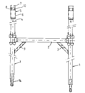
Fig. l depicts a view of a frame according to the
present invention;
Fig. 2 depicts an enlargéd view of a detail of the
upper end of a post of the frame of Fig. l;
Fig. 3 depicts a side view of the detail of Fig. 2;
Figs. 4 and 5 depict enlarged views of cross-sections
along lines IV-IV, and lines V-V respectively, in which a
post, which extends perpendicular to the depicted post, is
indicated with dashes in Fig. 4;
Fig. 6 depicts an enlarged view of a detail of the
lower end of a post of the frame of Fig. l; and
Fig. 7 depicts a cross-section along the line VII-VII
of Fig. 6.
Fig. 1 illustrates a frame comprising posts 1, which
are joined together by a cross beam 2 and a strut 3. Means,
not shown in detail, can be present at the cross beam for
the joining of rests or other construction elements to the
posts. Such elements can also be provided at other locations
on the posts, such as for-the assemblying of platforms.
As indicated in particular in Figs. 2 to 5, the upper
end 4 of a post 1 is provided with a bushing 5, of which
portion 6 extends beyond the end of the post. This end 6 is
provided with a recess 7 open at the top, and with a groove
8, which extends to the lower edge 9 of the bushing 5 but
which is delimitated by the upper edge 10 of the post 1. The
upper end 11 of the groove 8 lies in between the lower edge
12 of the recess 7 and the upper edge 13 of the bushing 5.
As apparent in particular from Figs. 1, 6 and 7, the
lower edge of a post 1 is provided with a pin 14, with a
square cross-section and with a bevelled end portion 15. The
pin 14 can be formed of a tubing member, and it is fixed in
the post by means of the weldings 16. Of course, another
method of joining the pin to the post can also be used.
The inner diameter DB of the bushing 5 is slightly
larger than the outer diameter DS of the post 1, as indica-
ted in Fig. 5. Because of this, the width BU of the recess 7
can be slightly larger than the diameter DS of the post 1,
,.

j
5 2112236 ::
while the recess still extends across less than 180 . Fur-
thermore, the width BS of the groove 8 will be slightly
larger than the size BV of a side of the square pin 14 -see
Fig. 7-
5During the assemblying of a frame on a frame already
standing vertically, the frame to be assembled is inserted
in hori20ntal position, with the pins 14 of both posts 1
being inserted in the grooves 8 via the recesses 7 till the
ends of the posts 1 come to rest against the walls of the
bushings 5.
A post of the frame to be assembled in the described
position is indicated with dashes in Figs. 3 and 4. The
frame is swung from this position into the vertical positi~ -
on, during which the pins 14 move through the grooves 8, so ;
that the frame is-guided during the swing. When the frame is
almost in the vertical position, then the posts 1 will fit
into the bushings 5. Then the frame will lower due to its
own weight, and the pins 14 will be received in the underly-
ing posts 1.
20To prevent the posts from being pulled out of the
underlying posts, a bore 17, and a bore 18 respectively, can
~be provided in the upper_ends 4 of each of the posts 1 and
in the pins 14, in which a locking pin, not specified fur-
ther, can be inserted.
25It will be apparent that only a possible embodiment of -'
a device according to the invention has been depicted in the
~drawings and specified above, and that numerous modificati-
ons can be brought about without departing from the spirit ~ - -
~ of the invention. ;
` ~ ~
~ ~ .
: -: :
: . ~ - :~
,:
: -, . " ~.
. . .
, .'; ~

Dessin représentatif
Une figure unique qui représente un dessin illustrant l'invention.
États administratifs

2024-08-01 : Dans le cadre de la transition vers les Brevets de nouvelle génération (BNG), la base de données sur les brevets canadiens (BDBC) contient désormais un Historique d'événement plus détaillé, qui reproduit le Journal des événements de notre nouvelle solution interne.

Veuillez noter que les événements débutant par « Inactive : » se réfèrent à des événements qui ne sont plus utilisés dans notre nouvelle solution interne.

Pour une meilleure compréhension de l'état de la demande ou brevet qui figure sur cette page, la rubrique Mise en garde , et les descriptions de Brevet , Historique d'événement , Taxes périodiques et Historique des paiements devraient être consultées.

Historique d'événement

Description Date
Inactive : CIB de MCD 2006-03-11
Demande non rétablie avant l'échéance 2000-12-27
Le délai pour l'annulation est expiré 2000-12-27
Réputée abandonnée - omission de répondre à un avis sur les taxes pour le maintien en état 1999-12-23
Lettre envoyée 1997-06-09
Exigences de rétablissement - réputé conforme pour tous les motifs d'abandon 1997-05-09
Inactive : Demande ad hoc documentée 1996-12-23
Réputée abandonnée - omission de répondre à un avis sur les taxes pour le maintien en état 1996-12-23
Demande publiée (accessible au public) 1994-06-29

Historique d'abandonnement

Date d'abandonnement Raison Date de rétablissement
1999-12-23
1996-12-23

Taxes périodiques

Le dernier paiement a été reçu le 1998-12-01

Avis : Si le paiement en totalité n'a pas été reçu au plus tard à la date indiquée, une taxe supplémentaire peut être imposée, soit une des taxes suivantes :

  • taxe de rétablissement ;
  • taxe pour paiement en souffrance ; ou
  • taxe additionnelle pour le renversement d'une péremption réputée.

Les taxes sur les brevets sont ajustées au 1er janvier de chaque année. Les montants ci-dessus sont les montants actuels s'ils sont reçus au plus tard le 31 décembre de l'année en cours.
Veuillez vous référer à la page web des taxes sur les brevets de l'OPIC pour voir tous les montants actuels des taxes.

Historique des taxes

Type de taxes Anniversaire Échéance Date payée
TM (demande, 3e anniv.) - générale 03 1996-12-23 1997-05-09
Rétablissement 1997-05-09
TM (demande, 4e anniv.) - générale 04 1997-12-23 1997-11-28
TM (demande, 5e anniv.) - générale 05 1998-12-23 1998-12-01
Titulaires au dossier

Les titulaires actuels et antérieures au dossier sont affichés en ordre alphabétique.

Titulaires actuels au dossier
SGB HOLDINGS LTD.
Titulaires antérieures au dossier
JOHANNES H. M. VAN HELMOND
JOHANNES HUBERTUS MARIA VAN HELMOND
Les propriétaires antérieurs qui ne figurent pas dans la liste des « Propriétaires au dossier » apparaîtront dans d'autres documents au dossier.
Documents

Pour visionner les fichiers sélectionnés, entrer le code reCAPTCHA :


Pour visualiser une image, cliquer sur un lien dans la colonne description du document. Pour télécharger l'image (les images), cliquer l'une ou plusieurs cases à cocher dans la première colonne et ensuite cliquer sur le bouton "Télécharger sélection en format PDF (archive Zip)" ou le bouton "Télécharger sélection (en un fichier PDF fusionné)".

Liste des documents de brevet publiés et non publiés sur la BDBC .

Si vous avez des difficultés à accéder au contenu, veuillez communiquer avec le Centre de services à la clientèle au 1-866-997-1936, ou envoyer un courriel au Centre de service à la clientèle de l'OPIC.


Description du
Document 
Date
(aaaa-mm-jj) 
Nombre de pages   Taille de l'image (Ko) 
Revendications 1994-06-28 2 134
Dessins 1994-06-28 2 75
Abrégé 1994-06-28 1 55
Description 1994-06-28 5 356
Dessin représentatif 1999-08-04 1 7
Avis de retablissement 1997-06-08 1 162
Courtoisie - Lettre d'abandon (taxe de maintien en état) 2000-01-19 1 185
Rappel - requête d'examen 2000-08-23 1 116
Taxes 1997-05-08 1 48
Taxes 1995-12-11 1 68