Note : Les descriptions sont présentées dans la langue officielle dans laquelle elles ont été soumises.
2112851
LOCKING APPARATUS
FIELD OF THE INVENTION
The present invention relates to locking apparatus
generally and more particularly to key blanks, keys, and locks
actuated thereby.
BACKGROUND OF THE INVENTION
A great variety of key blanks and associated locks are
known. In the prior art, key blanks include a generally elongate
unitary key cut-bearing portion with which is associated a key
head. Various types of cylinder locks are also known.
Relevant patents include U.S. Patent 4,377,082;
5,123,268; 3,287,945; French Patents 82.01.905 and 84.03.944 and
PCT published application 84.400.694Ø
SUMMARY OF THE INVENTION
The present invention seeks to provide an improved key
blank, key and lock.
There is thus provided in accordance with a preferred
embodiment of the present invention a key or key blank including
a generally elongate shaft portion defining a key combination
surface adapted to have formed thereon key cuts which define a
key combination, the key blank including a movable insert element
retained within the elongate shaft portion, the movable insert
element being displaceable in a single direction, outwardly from
the key combination surface.
There is also provided in accordance with a preferred
embodiment of the present invention a key or key blank including
a generally elongate shaft portion defining a key combination
-- ' 2 ~ 8 5 1
surface adapted to have formed thereon at a subsequent time, a
plurality of key cuts arranged in a row, which key cuts define a
key combination, the key blank including a movable insert element
retained within the elongate shaft portion, the movable insert
element arranged to lie along each row of key cuts.
There is additionally provided in accorda~ce with a
pre~erred embodiment of the present i~vention a key or key blank
including a yenerally elongate sha:Et portion defining a key
combination surface adapted to have formed thereon key cuts which
de~ine a key combination, the key ~lank including a movable
inserk element retained within the elongate shaft portion, the
movable insert element being selectably configurable to provide
multiple combinations.
In accordance with one embodiment of the present
invention, the movable insert element is configurable prior to
its insertion i~ the k~y blank.
In accordance with another preferred embodiment of the
present invention, the mo~vable insert element may be configurable
following its insertion in the key blank. Preferably the
configuration of the movable insert element can be carried out
using the same key cu~ting apparatus used for cutting the
ramaining key cuts on the key blank.
The key blank may also comprise a retractable cover
member for covering part o~ the shaft 'including the movable
insert element, whe~ it is not inserted in a lock keyway.
~ Preferably, the key blank is a reversible key blank
arranged to have formed thereon a pair of opposite key
combination sur~aces and includes a pair of movable insert
~ 2i1 2851
elements, each associated with one of the key combination
surfaces.
In accordance with a pre~erred embodiment of the inven-
tion one or mor~ movable insert elements may be provided having
the same or different configurations. In such a case, depending
on the orientation of the key it is operative to operate kwo
different and mutually exclusive master key systems.
Additionally in accordance with a preferred embodiment
of the present invention there is provided a lock cylinder con-
figured to be operated by a key of any of the types described
hereinabove, the lock comprising:
a housing;
a plug disposed in the housing, arxanged for rotation
relative thereto and de~ining a keyway;
a first plurality of chambers formed in the housing and
a second pluralit~ of chambers ~ormed in the plug on one side o~
khe keyway and being arranged such that each one of the first
plurality o~ chambers extends co~ qlly with a corresponding one
of the seco~d plurality o~ chamhers, whe~ the plug is in a first
rotational orientatio~ relative to the housing;
first pin assemblies b~i~g disposed in the first
plurality of ohambers a~d second pin assemblie~ being disposed in
the second plurality of chambers;
a thi.rd pin assembly being disposed in the plug on a
side of the keyway opposite to that of thP seeond pin assemblies
,.
; and being operative to urge said movable insert element outwardly
into engageme~t with one of the second pin assemblies.
''' 2 ~ 12851
The lock cylinder may be employed in arJy suitable kind
o~ lock, such as a door lock, a padlock or a year-shift lock.
In accordance with a preferred embodiment of the
present invention, the movable inse:rt element is formed with a
recess on its surface facing in the same direction as the key
combination surface.
Additionally in accordance with a preferred embodiment
of the present invention, the movable insert element may operate
with telescopic plug pins.
The present invention also seeks to provide an improved
cylinder lock which overcomes the limitations of the prior art.
There is thus provided in accordance with a preferred
emho~; r-nt of the present invention a cylinder lock including a
lock shell having a cylindrical ~ore formed therein, a plug
arranged for xotation within the cylindrical bore, the plug
ha~ing a plurality of annular groo~es iormed on an outer ~urface
thexeof, the plug bPing ~ormed with a ~eyway communicating with
the outer surface; a hive, including a plurality of pin assem-
blies therein and being arranged for operative engagement with a
correspon~; ng plurality of plug pin assemblies located within the
plug ~d a key having a plurality of exterior surfaces, one of
which being an edge surface which communicates with .the outer
~urface of the plug, the cylinder lock being characterized in
that the hive includes at least ona protrusion which is arranged
in juxtaposition with at least one of the plurality of annular
groo~es and the key is formed with at least one ~roove at its
edge surface corrasponding to the at least one protrusion.
In accordance with a preferred embodiment of the
-- ' 2 ~ S l
pxesent invention, the key is formed with pin positioning
recesses on one of the exterior sur~aces lying perpendicular to
the edge surface thereof.
Further in accordance with a preferred embodiment of
the present invention, there is provided a key blank having an
elon~ate shaft portion including a pair of side surfaces ar-
ranged to receive pin positioning recesses and a pair of edge
surfaces, at least one of which is ~ormed with at least one
gxoove ext~n~ing thereacross in a direc~ion perpendicular to the
longit~l~;n~ axi~ of the elongate shaft portion.
Additionally, in accordance with a preferred embodiment
of the present invention, there may be provided additional
protrusio~ b~aring members associated wi~h the lock shell and
having protrusions extending into one or more of the annular
grooves on the plug.
In accordance with a further ~ ';r~nt of the inven-
tion, there is provided a cylinder lock including a lock shell
having a bore formed therein, a bore lining element disposed in
the bore and ~e~; n; ng a~ inner bore having at least one an~ular
~oLlusion therein, a plug arranged for rotation within the inner
bore, the plug h~ving at least o~e annular groove formed on an
outer surface thereof, the plug being formed with a ke~way commu-
~icating with the outer surface; a hive, incl~lding a plurality of
pin assemblies therein and being arranged for operative engage-
ment with a corr~sponding plurality of plug pin assemblies locat-
ed within the plug and a key having a plurality of exteri.or
surfaces, o~e of~which being an edge surface which communicates
S 1
with the outer sur~ace of the plug, the cylinder lock ~eing
characterized in that the key is formed with at least o~e groove
at its edge surface corresponding to the at least one protrusion.
It is appreciated that the cylinder lock of the present
invention may be employed in any su.itable application, such as
door locks, padlocks and the like and may appear in any suitable
configuration.
It is a particular feature of the present inventlon
that the ward is retained in place by the body pins which prevent
removal of the ward even when a correct key is inserted into the
keyway. The only practical way to r~move the ward is by removing
the pin and spring assemblies.
The structure of the present i~vention enables thP
ward, which may be made of harde~ed metal, to provide additional
protectio~ to the body pins a~d to the shear line defined between
the plug and the ward.
Additionally in accoxdance with a preferred embodiment
of the present invention, th~ protrusio~s f ormed on the ward act
to ~Lev~nt the operation of the well-knowm technique of inserting
shims between the plug and the lock shell.
BRIE~ DESCRIPTION O~ T~E DRAWINGS
The prese~t invention will be understood and
appreciated m~xe fully from the following detailed description,
taken in conjunction with the drawings in which:
- Figs. lA and lB are pictorial illustrations showing two
t~pes o~ locks and keys;
Figs. 2A and 2B are pictorial illustrations ~f a key
blank and a key, respectively;
~. ;, ~ ~ . , ." - .
~112~
Figs. 3A, 3B, 3C and 3D are sectional illustrations
taken along lines III - III of FigO 2B, and illustrating four
different examples of the constructi.on and mountiny of movable
insert elements in a key;
Fig. 4 is a sectional illustration of a lock cylinder
having a key inserted thereini
Fig. 5 is a partially cut-way pictorial illustration of
part of the plug of the lock of Fig. 4, taken along lines V V
of Fig. 4;
Fig. 6 is a planar illustration of the keyway of the
plug of Fig. 5, takerl along the line VI in Fig. 5;
Figs. 7A and 7B are partia~ly cut away sectional
illustrations of the operation of two di~ferently configur~d
movable inserts in engagement with telescoping plug pins;
Figs. 8A and 8B are pictorial illustrations of a key
blank and a key;
~ ig~ 9 is an illustrati~n of a disassembled non-
rotatable movable insert assembly particularly useful ~or con-
figuration with con~entional key cutting de~ices;
Fig. 10 is a sectional illustration of the assembly of
Fig, 9 taken along the lines X - X in ~ig. 9;
Fig. 11 is an illustration of a disassembled non-
rotatable movable insert assembly particularly useful for insert
configuration with key cutting apparatus;
Fig. 12 is a sectional illustration of the assembly o~
Fig. 11 taken along the lines XII - XII in Fig. 11;
Figs. 13, 14 and 15 are illustrations of -three differ-
21128~
ent non-rotatable insert configurations;
Fig. 16 is a pictorial illustration of a cylindex lock;
Fig. 17 is an e~ploded view illustration of the
cylinder lock o-~ Fig. 16;
Fig. 18 is a pictorial illustrati~n of another cylinder
loc~;
Fig. 19 is an explodecl view illustration of the
cylinder lock of Fig. 18;
Fig. 20 is a sectional illustration taken along the
lines X~ - XX of ~ig. 16;
Fig. 21 is a sectional illustration taken along the
lines XXI - XXI of Fig. 18;
Fig. 22 is an i.llustration o~ a double sided key blank
useful with the apparatus of Fig6. 16 ~ 21;
~ igs. 23A and 23B are respective perpendicular sectio~-
al illustration~ of a padlo~k, Fig. 23B, being take~ along the
line~ B - ~ in Fig. 23~;
Fig. ~4 is an illustration of the engag~men~ of the
key, plug, hive a~d pins in the lock of Figs. 23~ and 23B;
Fig. ~5 is an exploded view illustration correspo~ding
to Fig. 24; and
Fig. 26 is a pictorial illustration of the key in the
padlork of Figs. 2~A - 25~
;. : . . : . .
2~:~28~1
DETAILED DESCRIPTION OF A PREFERRED EMBODIMENT
Reference is now made to Figs. lA and lB which
illustrate a key and cylinder lock constructed and operative in
accordance with a pre~erred embodiment of the present invention .
Fig. lA illustrates a door lock 10 e~mploying a cylinder ~2 and
key 14 according to the present invention, and Fig. lB
illustrates a padlock 16 employing a cylinder 18 and key 20
according to the prasent invention.
Broadly speaking, the key and the key blank used to
produce the key are characterized in that they include at least
one and preferably two movable insert elements haviny at least
one of the followi~g characteristics.
The insert element is arranged for movement in ~ single
direction perpendicular to the plane of the key and the lock
keyway.
The insert element is non~rotatable with respect to the
re~;n~er of the key.
The insert element is selectably configurable so as to
define a plurality of different permutationsO
~ he i~sert element includes a recess.
The insert element is arranged to lie along a row of
key cuts conventionally formed in the key and thus operates a
conventional plug pin of the lock.
, A pair of insert elements having different configura-
tions are associated with opposite key combination surfaces, thus
providing a double function key and key blank.
These arld other features of the key blank, kay and lock
of the present invention will be described hereinbelow with
9 . .
... ~ . . -
-'~ 2~12~5~
reference to the remainder o~ the drawings in order to provide a
comprehensive picture of the novel features of the invention
which is applica~le to any suitable cylinder lock context.
Reference is now made to Figs. 2A and 2s which
illustrate a key blank 22 and key Z4 constructed and operative
in accoxdance with a preferred embodiment of the present
invention. ~he common features o~ the key blank 22 and the key 24
will now be described using identical reference indications.
Both the key blank 22 and the key 24 comprise a
generally elongate shaft portion 26, preferably, but not
necessarily including first and second opposite planar surfaces
28 and 30~ at least on2 of which constitutes a k~y combination
surface 30 which is arranged to have formed thereon a plurality
of key cuts 32, which de~ine a lock combination in a conventional
ma~ner. When the ke~ blank 22 and the key 24 define reversible
keys, both of planar surfaces 2B and 30 constitute key
c~ ;n~tion sur~aces.
Preferably, each key cnmh;~tion ~urfac~ 30 also
defines elongate ~eyway guides 34, which fit i~ configuration to
protrusions defined in the interior of the keyway in the
corresponding lock, which will described hereinbelow. Some or all
of key cuts 32 may be formed over guides 34.
In accordance with a preferred embodiment of the
present inventio~ a movable insert element 40 is retained in
shaft portion 26 for motion, preferably in a single direction
only, perpendicu].ar to, i.e. in and out of the key combination
sur~ace 30. In reversible key blanks, as shown in Figs. 2A and
21~ 2~Sl
2B, a pair o~ oppositely directed movable insert elements 40 are
retained in sha~t portion 26, each for operative association with
a key combination surface.
In accordance with a preferred embodiment of the inven-
tion the pair of oppo~itely-directed movable insert elements may
have different configurations and positions. More than two
movable insert elements may be provicled with the same or di~fer~-
ent configurations and positions along the blank. In such a case,
depending on the orientation of the key it is operative to oper-
ate two different and mutually exclusive master key systems, each
of which is operated by a different insert element configuration.
Reference is now made to Figs. 3A - 3D which are taken
along the lines III - III in Fig. 2B and illustrate four
different examples of movable insert mountings and
configurations.
In the embodiment of Fig. 3A, the shaft 26 is formed
with a two step bore 42 for each insert element 41 and the insert
element 41 is pre~erably integrally formed with a plug pin
engaginy portion 44 having a facing ~nd 46 which can be
selectably con~;~ured to provide various combinations, preferably
a soc~et 48 of a desired depth; a broade~ed inte- ~iate portion
and a naL~wed pusher pin engagement portion 52. A ret~; n; ns
ring 54 preferably retains the insert element 41 against
disengagement Erom the shaft portion 26 in one direction and
engagement of intermediate portion 50 with a shoulder 56 retains
the insert element 41 against disengagement from shaft portion 26
in the other directionO
In the embodiment of Fig. 3B the same insert element 41
', ' 11
.
, . ;, , , - ~ " , . ~ ", . .
--' 2~8~ -
as in the embodiment of Fig. 3A may be employed. Here, however, a
single shoulder bore 60 is provided, having a peripheral recess
62, which accommodates a narrow peripheral protrusio~ 6~ of a
swaged retaining ring 66. Here also the two insert elements 41
are differently configured, so as to enable the key to be useful
for two different locks depending on the orientation of the key
in the keyway.
In the embodiment of Fig. 3C, a different type of
insert element 70 is shown and is preferably integrally ~ormed
with a plug pin engaging portion 74 having a facing end 76 which
can be selectably configured to provide various combinations,
pre~erably a socket 78 of a desired depth and a broadened portion
80 defining a pusher pin engagement surface 82. ~ retaining ring
84 is partially seated in a peripheral key cut 86 formed in
portion 74 adjacent end 76 and preferably retains the insert
element 70 against disengagement from the shaft portion 87 in one
direction and engagement of a shoulder between portions 74 and 80
of insert element 70 with a corresponding shoulder 88 i~.a bore
retai~s the insert eleme~t 70 against disenyagement from shaft
portio~ 87 in the other direction. Bore 90 also defines a
broadened portion which accommodates re~Ain;n~ ring 8~.
~ In the embodiment of Fig. 3D, yet another type of
insert element loo is shown and is pref~rably integrally formed
with a plug pin engaging portion 101 having a facing end 102
~hich can be ~electably configured to provide various
com~inations, preferably a socket 104 of a desired depth, and a
broadened portion 106 defining a pusher pin engagement surface
12
2 ~ 8 S l
108. No retaining ring is required inasmuch as the top of a bore
110 is swaged as indicated at reference numeral llZ to retain the
insert element lOo against disengagement from the sha~k portion
114 in one directi~n. Engagement of a shoulder between portions
101 and 106 o~ insert eleme~t loo with a correspondlng shoulder
116 in bore llo retains the insert element loo against
disengagement from shaft portion 114 i.n the other direction.
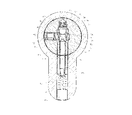
Reference is now made to Figs. 4, 5 and 6, which
illustrate a lock cylinder in operative engagement with a key
constructed in accordance with a preferred embodiment of the
present invention. It is to be appreciated that although the key
illustrated at reference numeral 120 in Fiy. 4 i~ the embodiment
shown in Fig. 3A, a~y suitable embodiment of key may be employed.
The lock cylind4r of Figs~ 4, 5 and 6 comprises a
housing 122 and a plug 124 which is arranged for rotation
relative thereto and def;n;ns a kayway 126.
A first plurality of chambers 128 are formed in the
housing 122 and a second plurality of chambers 130 are Eormed in
th~ plug on one side o~ the keyway and are arranged such that
each one of the first plurality of chambers 128 extends coaxially
with a corresponding one of the second plurality of chambers 130,
when the plug is i~ a first rotational orientation relative to
th~ housing, as shown in Fig. 4.
A plurality of first pin assemblies 132, which are
pr~ferably telescopic pin assemblies ha~ing a plurality of
con~centric pin portions as shown including a spring 131, are
preferably disposed in the first plurality of chambers 128 and
are retai~ed therein by plugs 134. A plurality of second pin
2 ~
assemblies 136, which are preferably telescopic pin assemblies
having a plurality of concentric pin portions as shown, are
disposed in the second plurality of chambers 130. A shear line
138 is defined between the facing surfaces of the respective
pluralities of ~irst and second pin assemblies 132 and 136, when
the proper key is located in its proper location in the keyway
126 in engagement with the second pin assemblies.
In accordance with a preferred embodiment of the
present invention a third pin assembly 140 is disposed in a
suitable single shoulder bore 142 in the plug 124 on a side of
the keyway 126 opposite to that of the second pin assemblies 130
and is operative to urge a movable insert element 150 outwardly
from the key combi~ation surface 152 of the key 120 into
operative engagement with one of the second pin assemblies 130.
Alternatively, the movable insert element 150 may operate against
an additional pin assembly which is not normally found in
conventional cylinders.
In the illustrated embodi~ent, the movable insext
element 150 may be identical to i~sert element 41 in the
embodiment of Fig. 3A. The third pin assembly 140 preferabl~
includes a pusher pi~ 154 having a rounded forward surface 156
and a broadened end poxtion 158, which is retained against
disengagement from plug 124 by a retAin;n~ ring 160. A spring
162, which is stronger than the spring 131 of pin assembly 132,
urges pusher pin 154 forwardly into displaci~g enyagement with
portion 52 of insert element 10, thus urging insert element 41
into operative engagement with one of the second pin assemblies
1~
2~128S~
130, as shown.
Key guide protrusions 164 are illustrated in Figs. 5
and 6.
Fig. 4 illustrates insert 41 having a socket 48 formed
at surface 46 thereof. Figs. 7A and 7B illustrate other possible
con~igurations of the forward sur~ace 46 of insert 41, which
enable various lock combinations to be realized thereby. In Fig.
7A, the forward surface is flat, as indicated by reference
numeral 170. In Fig. 7B, the forward surface 172 is a combination
recess and central protrusion. It is appreciated that any other
suitable surface configuration may be provided.
Refere~ce is now made to Figs. 8A and 8B which illus-
trate an alternative embodiment of the key blank and key of Figs.
2A and 2B wherein the movable inserts 180 are located beyond the
normal key cuts 182 and keyway engaging guides 184. In such a
case, an additional plug pin and housing pin (not shown) must be
provided for being operated hy the movable insertG
It is a particular feature of the present inve~tion
that the configuration of the plug pin engagement surface of the
mova~le insert may be selectably configured either as park of the
manufacture of the key blank, or thereafter, when the key cuts
are bein~ made. In the latter case, the same ~-ch;nery u~ed for
cutting the r~ -i n; ng key cuts can be employed for con~iguring
the plug pin engagement surfase of the movable insert element.
This is made possible by impeding rotation of the movable insert,
as is illustrated in Figs. 9 - 15.
Reference is now made to Figs. 9 - 15 which illustrate
the construction and mounting of a non-rotatable movable insert
21128~1
element in a key blank. As seen in Figs. 9 and lO, a movab]e
in~ert element 200 may be generally identical to inserk element
41 of Fig. 3A with the additional provision of a radially extend-
ing protrusion 202 which seats in a corresponding recess 204 in
a bore 205 formed in the key blank shaft 208. The movable plug
may be retained, similarly to the embodiment of Fig. 3A, by a
ret~;n;ng ring 210 in press-fit enc7agement with a portion of
bore 206.
According to an alternative embodiment of the present
invention, as seen in Figs. 11 and 12, a movable insert element
220 may be generally .identical to insert element 41 of Fig. 3A
with the additional provision of one or more radially extending
recesses 222. The movable plug is retained against rotation by a
ret~;n;ng ring 230, which is formed with protrusions 224 which
corresponding to and seat in recesses 222, which is held in non
rotatable press-fit engagement with a portion of a bore 232 in a
ke~ blank shaft 234.
Fig~. 13, 14 and 15 illustrate three additional .illus-
trative examples of non-rotating movable insert elements, indi-
cated by reference numerals ~40, 242 and 244 which may be re-
tai~ed i~ a corresp~n~i n~ suitably shaped bore ~50, 252 and 25~
in corresponding key bla~k shaft portions 260, 262 and 264. The
insert elements of Figs. 13 - 15 are typlcally retained against
disen~agement by swaging of the respective bores.
It is to be appreciated that any suitable type of non
rotating movable insert elements may be employed. Their
configuration and mounting is not limited by the examples
16
21~28S~
provided herein.
Reference is now made to Figs. 16, 17 and 20 which
illustrate a cylinder lock constructed and operative in
accordance with a preferred embodiment of the present invention.
The cylinder lock, which may be a single cylinder or a double
cylinder, as shown, of any suitable configuration comprises a
lock shell 310 having at least one elongate generally cylindrical
bore 312.
In accordance with a preferred embodiment of the
present invention, there is disposed in bore 312 a plug 314 which
is arranged ~or rotation about the longitu~; n~l axis 316 of bore
312 and which is formed with a plurality of annular grooves 318
on an outer surface 320 thereof, the grooves 318 extending
generally in planes perpe~dicular to longitu~; n~l: axis 316.
Disposed in lock shell 310 is a hive element 322, which
is referred to herein generally as a hive, which contains a
plurality of pin and spring assemblies 324 which m y be of
entirely conventional constxuction or may be telescopic, as shown
in applicant's U.S. Patent 5,123,268O ~ive 322 is formed with
surface 326 which effectively forms part o~ the i~ner facing
surface o~ bore 312. This surface is formed with bores 328
through which respective body pins 330 and plug pi~s 332l which
form part of pin and spring a~semblies 324, extend.
In accordance with a preferred embodiment of the
present invention~ surface 326 is formed with one or more protru-
sions 334 which are configured and located such that they lie in
one or more of annular grooves 318 of plug 314. Protrusions 334
are preferably in the form of grooved protrusions which extend
17
2~2~1
along the entire cylindrical extent o~ surface 326 as shown in
Fig. 17, but they need not necessary bc so configured.
Normally, as in the illustrated embodiment of Fig. 17,
the hive element 322 is separate from the remainder of the hive
in which the pin and spring assemblies 324 are located.
Alternatively, the entire hive may he formed as a single piece.
Additionally in accordance with a preferred embodiment
of the invention, one or more inserts 340 are additionally
provided, having corresponding edge surfaces 342, which
ef~ectively form part of the inner facing surface of bore 312.
These inserts may also be provided with one or more protrusions
344 which are configured and located so as to lie within annular
yro~ves 318. Inserts 340 may be retained in slots 346 formed in
the lock shell 310.
It is a p~rticular feature of the present invention
that the provision of protrusion6 334 on hive 322 requirPs that
the key blank used to foxm a key suitable ~or use with the
cyllnder should be configured to haye corresponding grooved
recesses thereon. Since such grooved recesses cannot be formed by
conventional key cutting apparatus, they ~ust be present in th
key blank produced by a manufacturer~
This arrangement allows the manu~acturer the
possibility of oontrolling a relatively large number of dif~erent
key blank co~figurationsO ~he provision of multiple elements
having inner facing protrusions communicating with the interior
of bore enables key mastering to he carried ouk in a convenient
manner. It also can be used to limit ~ngular rotation of the key.
1~
21128~
Reference is now made to Figs. 18, lg and 21 which
illustrate a cylinder lock constructed and operative in
accordance with an alternative embodiment of the present
invention. The cylinder lock, which may be a single cylinder or a
double cylinder, as shown, of any suitable configuration
comprises a lock shell 380 having at least one elongate generally
cylindrical bore 382.
In accordance with a preferred embodiment of the
present invention, there is disposPd in bore 382 a plug assembly
384 which includes a plurality of bore liner elements 385 and a
plug 386, which is arranged for rotation about the longitll~; nal
axis 387 of bore 382, and which is formed with a plurality of
annular grooves 388 on an outer surface 390 thereof, the grooves
388 exten~; ng generally in planes p~rpendicular to longitudinal
axis 387.
As seen in Fig. 19, parts of the bore liner elements
385 define a hive element 392, which contains a plurality of
bores 398, through which extend body pi~s 400 and 402 which form
part of pin and spring assemblies 394 which may be of entirely
conventional construction or may be telescopic, as shown in
applicant's U.S. Patent 5.123.268. Bore liner elements 385 a~d
thus hive 392 is formed with an inner surface 389 which
e~fectively forms part of the inner facing surface of bore 382.
In accordance with a preferred embodiment of the
present invention, sur~ace 389 is formed with one or more protru-
sions 394 which are configured and located such that they lie in
one or more of annular groo~es 388 of plug 3860 Protrusions 394
are preferably in the form of grooved protrusions which extend
19
-~- 21i~
along the entire cylindrical extent of surface 389 as shown in
Fig. 19, but they need not necessary he so confiyured.
The cooperation between the apparatus illustrated in
Fig. 19 and a key 396 inserted into the keyway 395 of bore 38~ is
illustrated i~ Fi~. 21. Fig. 22 illustrates a preferred key blank
for a wherein different key blank groove arrangements 399 on the
two edges of key 396 can clearly be seen in addition to
conventional pin engaging recesses 397 on the larger surfaces of
the key blank, which lie perpendicular to the edges thereof. This
arrangement can be useful when a single key can be used for
opening two dif~erent locks~ depending on the orientation of the
key in the keyway. Alternatively, identical key blank groove
arrangement~ may ~e provided on both sides, as for a reversible
key.
Reference is now made to Fiys. 23A and 23B, which
illu~trate a cylinder lock of the type described h~reinabove in
the context of a padlock. Here the plug is indicated by
reference numeral 420 and the hive b~ re~erence numeral 422. It
is seen that the hive 422 has a plug Facing surface 424 which is
formed with a plurality of protrusions which are configured and
located so as to be accommodated by one or more of a plurality of
grooves 426 formed on plug 420. A key 430 is formed with edge
grooves corresponding to the protrusions 458 on plug facing
surface 424 of hive 422.
The lock and key arrangement of the present invention
may be used fvr other types of locks as well.
Reference is now made to Figs. 24 - 26, which
illustrate the lnteraction of a key ~o, with a plug 420, and
hive 422 in accordance with a preferred ernbodiment of the
invention. In the illustrated ernbodiment, the cylindrical surface
424 of the hive 422 is formed with a total of thr0e protrusions
458, which are configured and located to lie within three of the
five correspanding annulax grooved recesses 426 in plug 420. An
edge surface 462 of key 430 is formed with grooved recesses 464
which correspond in location and sectional configuration to
protrusions 458, such that rotation of the plug 420 with the key
430 fully inserted into the keyway thereo~, as indicated by
arxows ~66, past protrusions 458 is permitted.
It is particularly noted that in accordance with a
preferred embodiment of the present invention, 'che plug pins 468
in hive 422 engage conventional recesses 470 formed on a side
surface of the key 430, which lies perpendicular to the edge
surface 462 of the key. It is noted that where a reversible key
is provided, as shown in Fig. 26, grooved recesses 464 are
provided on both edge surfa~es of the key blank.
It i~ additionally noted that grooved recesses 464 are
formed with a generally uniform cross section lying in planes
perpendicular to edge surface 462
It is appreciated that normally there will be a lesser
number of protrusion~ 458 than annular groove recesses 426, such
that a large number of different key blanks may be produced to
correspond ko the large number of combinations of different
numbers and locations of protrusions 458.
It will be appreciated that a key blank, a key and a
lock operated thereby which combines any of the above-described
21
--~ 2112851
features, and particularly any oE the ~eatures shown in Figs. 1 -
15 with any of the features in Figs. 16 - 26 is also within the
scope of the present invention.
It will be appreciated by persons skilled in the art
that the present invention is not limited by what has been
particularly shown and described hereinabove. Rather the scope o~
the present invention is defined only by the claims which follow:
22