Sélection de la langue

Search

Sommaire du brevet 2113286 

Énoncé de désistement de responsabilité concernant l'information provenant de tiers

Une partie des informations de ce site Web a été fournie par des sources externes. Le gouvernement du Canada n'assume aucune responsabilité concernant la précision, l'actualité ou la fiabilité des informations fournies par les sources externes. Les utilisateurs qui désirent employer cette information devraient consulter directement la source des informations. Le contenu fourni par les sources externes n'est pas assujetti aux exigences sur les langues officielles, la protection des renseignements personnels et l'accessibilité.

Disponibilité de l'Abrégé et des Revendications

L'apparition de différences dans le texte et l'image des Revendications et de l'Abrégé dépend du moment auquel le document est publié. Les textes des Revendications et de l'Abrégé sont affichés :

  • lorsque la demande peut être examinée par le public;
  • lorsque le brevet est émis (délivrance).
(12) Brevet: (11) CA 2113286
(54) Titre français: COUSSIN GONFLABLE POUR VEHICULES AUTOMOBILES
(54) Titre anglais: AIR BAG ASSEMBLY FOR MOTOR VEHICLES
Statut: Périmé et au-delà du délai pour l’annulation
Données bibliographiques
(51) Classification internationale des brevets (CIB):
  • B60R 21/20 (2011.01)
  • B60R 21/16 (2006.01)
(72) Inventeurs :
  • HUMPHREYS, GERARD J. (Etats-Unis d'Amérique)
  • BREED, ALLEN K. (Etats-Unis d'Amérique)
  • THUEN, TORBJORN (Etats-Unis d'Amérique)
(73) Titulaires :
  • BREED AUTOMOTIVE TECHNOLOGY, INC.
(71) Demandeurs :
  • BREED AUTOMOTIVE TECHNOLOGY, INC. (Etats-Unis d'Amérique)
(74) Agent: MARKS & CLERK
(74) Co-agent:
(45) Délivré: 1997-10-07
(22) Date de dépôt: 1994-01-12
(41) Mise à la disponibilité du public: 1994-07-26
Requête d'examen: 1994-01-12
Licence disponible: S.O.
Cédé au domaine public: S.O.
(25) Langue des documents déposés: Anglais

Traité de coopération en matière de brevets (PCT): Non

(30) Données de priorité de la demande:
Numéro de la demande Pays / territoire Date
008,689 (Etats-Unis d'Amérique) 1993-01-25

Abrégés

Abrégé français

Un coussin gonflable pour volant ou pour toute autre partie du compartiment passager d'un véhicule à moteur et comprenant un ensemble pour coussin gonflable, un logement libre pour l'ensemble et un couvercle. L'ensemble pour coussin gonflable, lorsqu'il n'est pas fixé à son logement, est désarmé pour éviter que le coussin se gonfle accidentellement. Le coussin d'air est armé au cours de son installation dans le logement. Le logement et l'ensemble sont conçus pour empêcher la pose du couvercle si l'ensemble pour coussin gonflable n'y est pas ou a mal été installé afin d'éviter que le coussin soit armé. Lorsque l'ensemble pour coussin gonflable est retiré de son logement, il est désarmé automatiquement.


Abrégé anglais


An air bag system designed for mounting on a
steering wheel or other member of a motor vehicle
passenger compartment includes an air bag assembly,
an open housing for the same and a cover. The air
bag assembly while separated from its housing is
disarmed to prevent accidental deployment. The air
bag is armed during its installation in the housing.
The housing and assembly are constructed so that the
cover cannot be installed if the air bag assembly is
missing or it has been installed improperly so that
it is not armed. When the air bag assembly is
removed from the housing, it is automatically
disarmed.

Revendications

Note : Les revendications sont présentées dans la langue officielle dans laquelle elles ont été soumises.


We claim:
1. An air bag system for mounting on a motor vehicle
comprising:
an air bag assembly including a gas generator having an
armed and a disarmed state;
housing means disposed in said motor vehicle for housing
said gas generator, said housing means including mounting means
for mounting said gas generator and securing said gas generator
to said housing means, said mounting means cooperating with said
gas generator for automatically arming said gas generator when
said gas generator is secured to said housing means;
cover means for closing said housing means; and
cover prevention means for preventing said cover means from
being installed on said housing means if said gas generator is
in said disarmed state.
2. The air bag assembly of claim 1 with said mounting means
further including arming means for arming said gas generator.
3. The air bag assembly of claim 2 wherein said arming means
is arranged to disarm said gas generator when said air bag
assembly is removed from said housing means.
4. The air bag assembly of claim 1 wherein said cover
prevention means includes means for preventing said cover means
from being installed on said housing means when said air bag
assembly is missing from said housing means.

5. An air bag system for mounting on a motor vehicle
comprising:
an air bag assembly including a gas generator having an
armed and a disarmed state;
housing means disposed in said motor vehicle for housing
said air bag assembly;
mounting means for mounting said gas generator in said
housing means, said gas generator having a first position with
respect to said mounting means in which said gas generator is in
said disarmed stated and said gas generator is removable from
said housing means, said gas generator being movable into a
second position in which said gas generator and said mounting
means are interengaged to retain said gas generator in said
housing means, said gas generator and said mounting means
cooperating to arm said gas generator automatically to said armed
state when said gas generator is in said second position.
6. The air bag system of claim 5 further comprising a cover for
closing said housing means.
7. The air bag system of claim 6 further comprising cover
prevention means for preventing the installation of said cover
over said housing means if said sensor is not armed by said
arming means.
8. The air bag system of claim 7 wherein said air bag is
disposed within said cover.

9. The air bag assembly of claim 8 wherein said air bag is
formed with an opening with said gas generator being fit into
said opening.
10. The air bag assembly of claim 5 further comprising an
acceleration sensor disposed in said gas generator.
11. An air bag system for a motor vehicle with a passenger
compartment, said system comprising:
an air bag assembly including a gas generator having an
accelerator sensor, and an inflatable air bag disposed around
said gas generator;
an open housing formed in said passenger compartment and
shaped to receive said air bag assembly, and including mounting
means for mounting said gas generator and securing said generator
to said arming means for arming said sensor when said gas
generator is inserted into said housing; said arming means
cooperating with said mounting means for automatically arming
said sensor when said gas generator is secured to said open
housing; and
cover means for covering said open housing.
12. The air bag system of claim 11 wherein said arming means
includes a rotary member and a fixed member.
13. The air bag system of claim 12 wherein said rotary member
is disposed in said sensor, and said fixed member is affixed to
said housing and arranged to engage said rotary member.

11
14. The air bag system of claim 11 wherein said gas generator
includes a shell and a tongue extending from said shell, and
wherein said housing includes a plate for engaging said tongue
for securing said gas generator in said housing.
15. The air bag system of claim 11 further including cover
prevention means for preventing the installation of said cover
when said gas generator is missing.
16. The air bag system of claim 11 further including cover
prevention means for preventing the installation of said cover
when said gas generator is not armed.
17. The air bag system of claim 16 wherein prevention means
comprises a protrusion member and a hole for said protrusion
member.
18. The air bag system of claim 17 wherein said protrusion
member is disposed on said cover and said hole is formed on said
housing.
19. The air bag system of claim 18 wherein said housing means
includes a plate movable to selectively cover said hole.
20. The air bag system of claim 19 wherein said plate is movable
by said gas generator.
21. The air bag system of claim 11 further including disarming

12
means for disarming said air bag when said air bag is removed
from said housing.
22. An air bag system for a motor vehicle with a passenger
compartment, said system comprising:
an air bag assembly including a gas generator having an
accelerator sensor, and an inflatable air bag disposed around
said gas generator;
an open housing formed in said passenger compartment and
shaped to receive said gas generator;
arming means for arming said sensor when said gas generator
is inserted into said open housing, wherein said arming means
includes a rotary member and a fixed member, said rotary member
being disposed in said sensor, and said fixed member being
affixed to said open housing and arranged to engage said rotary
member to arm said sensor when said sensor is rotated with
respect to said housing; and
cover means for covering said open housing.
23. An air bag system for a motor vehicle with a passenger
compartment, said system comprising:
an air bag assembly including a gas generator having an
accelerator sensor, and an inflatable air bag disposed around
said gas generator, said gas generator including a shell and a
tongue extending from said shell;
an open housing formed in said passenger compartment and
shaped to receive said gas generator, said open housing including
a plate for engaging said tongue for securing said gas generator

13
to said open housing;
arming means for arming said sensor when said gas generator
is inserted into said open housing;
cover means for covering said open housing; and
cover prevention means for preventing the installation of
said cover when said gas generator is not armed, wherein said
cover prevention means includes a protrusion member and a hole
for said protrusion member.
24. The air bag system of claim 23 wherein said protrusion
member is disposed on said cover and said hole is formed on said
housing.
25. The air bag system of claim 24 wherein said housing includes
a plate movable to selectively cover said hole.
26. The air bag system of claim 25 wherein said plate is movable
by said gas generator.

Description

Note : Les descriptions sont présentées dans la langue officielle dans laquelle elles ont été soumises.

2113~86
BACRGROUND OF THE INVENTION
a. Field of Invention
The present invention pertains to an improved air
bag assembly for motor vehicles particularly suited
for installation in a small space, such as the
steering wheel, and more particularly, to an air bag
assembly with coupling means to insure that the
assembly is installed in a motor vehicle safely and
correctly.
b. Description of the Prior Art
Typically an air bag assembly for a motor vehicle
consists of a mechanical or electrical sensor, a gas
generator connected to the sensor and a bag arranged
for inflation from gasses from said generator. In
operation, when the sensor detects that the motor
vehicle is subjected to a deceleration of a preset
magnitude and duration, it sets off the gas generator
which in turn inflates the bag. During the
installation or removal of the assembly, the sensor
should be disarmed to insure that the gas generator
is not activated accidentally, for example if the
assembly is dropped, or jarred. This problem is
especially important for assemblies with mechanical
sensors. However, once the assembly is installed the

2113286
sensor should be armed, otherwise the air bag
assembly is non-functional and therefore useless.
However, prior art assemblies had no installation or
disassembly provisions which operated satisfactorily.
OBJECTIVES AND SUMMARY OF THE INVENTION
Therefore it is an objective of the present
invention to provide an assembly in which the sensor
is automatically disarmed when not installed onto the
vehicle, and is armed when the installation of the
gas generator is completed.
A further objective is to provide an assembly with
means of assuring that the installation of the system
cannot be completed if the sensor is disabled.
A further objective is to provide an assembly
which can be installed easily and without the use of
special tools.
Other objectives and advantages of the invention
shall become apparent from the following description.
The present invention pertains to a self-contained
air bag system disposed in a well formed in the
steering wheel. The system includes a cover for the
well, an inflatable air bag disposed in the cover, a
gas generator disposed in the well and various
hardware for mounting the above mentioned elements on
the steering wheel. These various elements cooperate
to insure that the gas generator is armed and the
cover is installed only if the gas generator is
properly installed in the well. Removal of the gas
generator automatically disarms it.

~113286
BRIEF DESCRIPTION OF THE DRAWINGS
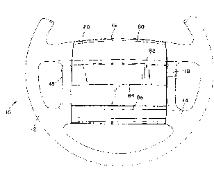
Figure 1 shows a plan view of a steering wheel
with an air bag assembly constructed in accordance
with this invention;
Figure 2 shows a plan view similar to Figure 1
showing a well within the steering wheel for housing
the assembly;
Figure 3 shows a top view of the gas generator for
the assembly;
Figure 4 shows a bottom view of the gas generator
of Figure 3;
Figure 5 shows a side view of the gas generator of
Figures 3 and 4;
Figure 6 shows the gas generator installed in the
steering wheel well, with the sensor disarmed;
Figure 7 shows the gas generator of Figure 6 with
the sensor armed;
Figure 8 is partial side-sectional view taken
along line 8-8 in Figure 7;
Figure 9 shows a bottom view of the steering wheel
cover with the air bag;
Figure 10 shows a side sectional view of the air
bag assembly installed in the steering wheel; and
Figure 11 shows an exploded side view of the
assembly.

21132~
DETAILED DESCRIPTION OF THE lNv~NlION
Referring now to the Figures, Figure 1 shows a top
view of an assembled steering wheel 10 having a rim
12 joined by several spokes 14 to a central hub 16.
Although the shape of the hub 16 is immaterial for
the present invention, in the embodiment of Figure 1,
the hub 16 is generally rectangular. Disposed on two
lateral sides of the hub there are a plurality of
switches 18 associated with the operation of the
motor or its accessories. Also mounted on hub 16 is
a cover 20. The cover 20 is secured to the wheel 10
as described below.
Figure 2 shows the steering wheel 10 with the
cover 20 and other air bag elements removed. As seen
in Figures 2 and 10, steering wheel 10 is formed with
a well 22 holding a metal backing plate 26. Backing
plate 24 defines a circular opening and which lip 26
is interrupted by three arcuate notches 28, 30, 32.
Notches 28 and 30 extend over an arc of circular much
smaller than notch 32.
The well 22 is also provided five through holes
for mounting the cover 20. Four of these holes 34,
36, 38 and 40 are always exposed while the fifth hole
42 is covered by a sliding plate 44. Sliding plate
44 is slidably mounted on backing plate 26 and has
an arcuate slot 46 engaged by two guiding pins 48,
50. A spring (not shown) disposed below the sliding
plate 44 is used to bias this sliding plate 44 to the
position shown in Figure 2 wherein the sliding plate
44 covers hole 42.
A shaft 53 extends upwardly from the bottom of
well 22. As seen in Figure 2, shaft 53 has a D-
shaped cross-section.
Well 22 is also used to hold a gas generator 54
shown in detail in Figures 3-5. This gas generator

~ 2 ~ 8 ~
may be constructed for example from aluminum and have the
structure as described in U.S. Patent No. 5,197,757 identified
above. Gas generator 54 includes a cylindrical body 56 with a
plurality of holes 58. The body 56 has a bottom plate 60 with
three arcuate tongues 62, 64 and 66 dimensioned to fit into
notches 28, 30 and 32 of backing plate 26, respectively. Tongue
66 is provided with a lateral projection 68 having a round hole
70. Within gas generator 54 there is an acceleration sensor 72
with a D-shaped hole 74. This sensor may be for example a
mechanical sensor as described in U.S. Patent No. 5,197,757
identified above. When gas generator 54 is not installed, its
sensor 72 is disarmed so that the generator is not set off even
if it is accidentally dropped, hit with a hammer, and so on.
The gas generator 54 is installed into the wheel 10 as
follows. First, the gas generator 54 is positioned in the well
22 with shaft 53 inserted in hole 74 and tongues 62, 64, 66
inserted into notches 28, 30, 32 as shown in Figure 6. The gas
generator 54 is then rotated clockwise, as indicated by arrow A,
causing the tongues 62, 64, 66 to slip under the lip 26 of plate
24. The gas generator 54 and plate 24 are dimensioned so that
an interference fit is formed therebetween to maintain the gas
generator 54 in place. Importantly, as gas generator 54 is
rotated, shaft 53 remains fixed, thereby arming the sensor 72.
In addition, as shown in Figure 7, as the gas generator at the
end of its travel, pro~ection 68 pushes the slide plate 48 to the
right, uncovering hole 42. Thus, when the gas generator 54 is
in its secured and armed position shown in Figure 7, hole 42
A

211~286
is uncovered since sliding plate 44 is pushed aside,
and is aligned with hole 70.
The cover 20, as shown in Figures 9 and 10,
includes a top panel 80. This panel 80 is made of
plastic or leather and has several parallel grooves
82, 84, 86 (shown in Figure 1). On its bottom
surface 88, cover 20 has a cylindrical wall 90.
Inside cover 20, there is a folded air bag 91 (Figure
10). The cover 20 also has five downwardly extending
studs 92, 94, 96, 98 and 100 which fit into holes 34,
36, 38, 40 and 42 respectively when the cover is
installed over well 22. Studs 92, 94, 96 and 98 are
preferably threaded. Once the cover 20 is installed
over the well 22, its studs extend under the steering
wheel so that it may be secured by nuts such as nut
102 (Figure 10). Wall 90 is arranged to fit
telescopically about gas generator 54.
Once the cover 20 is secured, the air bag assembly
is armed and operational. If the motor vehicle is
involved in a crash, the acceleration sensor 72
triggers the gas generator which emits an inflator
gas through its holes 58. The cover Z0 is arranged
over the generator, so that this gas is channeled
into the air bag 91. The air bag 91 than quickly
expands breaking panel 80 along its parallel grooves.
The gas generator assembly described above has a
number of very advantageous features. When
disassembled, its gas generator is disarmed and
therefore the components of the assembly are safe to
handle. The cover 20, generator 54 and the backing
plate 24 cooperate to prevent an improper or
incomplete installation. More particularly, the
cover 20 cannot be installed into well 22 without the
gas generator being installed properly of the

211328~
operation of the sliding plate 44. Plate 44 allows
the proper installation and securing of cover 20 only
after gas generator 54 is seated and armed within the
well 22. Finally, if the air bag assembly has to be
5dismounted, the gas generator cannot be removed from
the well before it is disarmed by rotating it
counterclockwise with respect to shaft 53. If the
gas generator 54 is not disarmed, it is prevented
from being removed by backing plate 24.
10In the above-described embodiment the air bag
assembly is shown installed on a steering wheel,
however, it may be installed on other parts of a
motor vehicle, for example over a glove compartment.
Obviously numerous other modifications may be made
15to the invention without departing from its scope as
defined in the appended claims.

Dessin représentatif
Une figure unique qui représente un dessin illustrant l'invention.
États administratifs

2024-08-01 : Dans le cadre de la transition vers les Brevets de nouvelle génération (BNG), la base de données sur les brevets canadiens (BDBC) contient désormais un Historique d'événement plus détaillé, qui reproduit le Journal des événements de notre nouvelle solution interne.

Veuillez noter que les événements débutant par « Inactive : » se réfèrent à des événements qui ne sont plus utilisés dans notre nouvelle solution interne.

Pour une meilleure compréhension de l'état de la demande ou brevet qui figure sur cette page, la rubrique Mise en garde , et les descriptions de Brevet , Historique d'événement , Taxes périodiques et Historique des paiements devraient être consultées.

Historique d'événement

Description Date
Inactive : CIB désactivée 2020-02-15
Inactive : CIB attribuée 2019-11-27
Inactive : CIB en 1re position 2019-11-27
Inactive : CIB expirée 2011-01-01
Inactive : CIB de MCD 2006-03-11
Le délai pour l'annulation est expiré 2003-01-13
Lettre envoyée 2002-01-14
Accordé par délivrance 1997-10-07
Inactive : Renseign. sur l'état - Complets dès date d'ent. journ. 1997-08-05
Inactive : Dem. traitée sur TS dès date d'ent. journal 1997-08-05
Inactive : Lettre officielle 1997-07-28
Préoctroi 1997-05-29
Un avis d'acceptation est envoyé 1996-12-17
Demande publiée (accessible au public) 1994-07-26
Toutes les exigences pour l'examen - jugée conforme 1994-01-12
Exigences pour une requête d'examen - jugée conforme 1994-01-12

Historique d'abandonnement

Il n'y a pas d'historique d'abandonnement

Historique des taxes

Type de taxes Anniversaire Échéance Date payée
Taxe finale - générale 1997-05-29
TM (brevet, 4e anniv.) - générale 1998-01-20 1997-12-22
TM (brevet, 5e anniv.) - générale 1999-01-12 1998-12-16
TM (brevet, 6e anniv.) - générale 2000-01-12 1999-12-20
TM (brevet, 7e anniv.) - générale 2001-01-12 2000-12-19
Titulaires au dossier

Les titulaires actuels et antérieures au dossier sont affichés en ordre alphabétique.

Titulaires actuels au dossier
BREED AUTOMOTIVE TECHNOLOGY, INC.
Titulaires antérieures au dossier
ALLEN K. BREED
GERARD J. HUMPHREYS
TORBJORN THUEN
Les propriétaires antérieurs qui ne figurent pas dans la liste des « Propriétaires au dossier » apparaîtront dans d'autres documents au dossier.
Documents

Pour visionner les fichiers sélectionnés, entrer le code reCAPTCHA :


Pour visualiser une image, cliquer sur un lien dans la colonne description du document. Pour télécharger l'image (les images), cliquer l'une ou plusieurs cases à cocher dans la première colonne et ensuite cliquer sur le bouton "Télécharger sélection en format PDF (archive Zip)" ou le bouton "Télécharger sélection (en un fichier PDF fusionné)".

Liste des documents de brevet publiés et non publiés sur la BDBC .

Si vous avez des difficultés à accéder au contenu, veuillez communiquer avec le Centre de services à la clientèle au 1-866-997-1936, ou envoyer un courriel au Centre de service à la clientèle de l'OPIC.


Description du
Document 
Date
(aaaa-mm-jj) 
Nombre de pages   Taille de l'image (Ko) 
Abrégé 1995-06-09 1 29
Dessins 1995-06-09 6 214
Description 1995-06-09 7 303
Revendications 1995-06-09 4 142
Description 1996-12-16 7 237
Revendications 1996-12-16 6 180
Dessin représentatif 1997-10-01 1 7
Avis concernant la taxe de maintien 2002-02-10 1 179
Taxes 1997-12-21 2 58
Correspondance 1997-07-27 1 12
Correspondance 1997-07-27 1 17
Taxes 1996-11-21 1 48
Taxes 1996-01-08 1 53
Correspondance reliée au PCT 1997-05-12 1 46
Correspondance de la poursuite 1996-11-11 4 94
Demande de l'examinateur 1996-07-25 3 114
Correspondance reliée au PCT 1997-05-28 2 70