Note : Les descriptions sont présentées dans la langue officielle dans laquelle elles ont été soumises.
W,,093/01887 2 1 1 3 6 3 2 PCT/US92/~ ~8
ADVANCED FRACTURE BLADE AND METHOD OF OPERATION
FOR FLUORESCENT TUBE DIGESTER
Related ADplications
This application is related to severai prior
applications filed by the same inventor and particularly
to the application entitled "Fluorescent Tube Crusher
with Particulate Separation and Recovery", which
discloses, among other things, a particular type of
rotating fracture blade for crushing fluorescent tubes.
Background of the Invention
(l) Field o the Invention.
.
The present invention relates to the crushins
or digesting of used fluorescent tubes. More
particularly the present invention relates to an
l~ improved rotatable crushing blade and the method of
using such blade for the effective crushing of used
fluorescent tubes into substantially uniform sized
pieces of glass or pieces of glass within a uniform
range of sizes prior to separating the glass and various
~o potentially tOXlC materials contained witr.in the
interior of the fluorescent tubes from each other.
More particularly, the present invention relates to an
improved shape of a fluorescent tube,fracturing blade
and a range of speeds for operation of such blade which
2~ provides the desired results, i.e. the desired
separation of the fractured glass particulates and the
toxic powder and other substances contained originally
within the fluorescent tubes.
.
(2) Discussion of the Prior Art.
Fluorescent light tubes are formed from
elongated, cylindrical or tubular glass receptacles
which are charged with mercury or cther conductlve
vapors. The inside surface of the tube is coated wlth
WO~3/01887 PCT/US92/05~X
3~
a fluorescent coating of some form such as phosphorus
itself or other phosphor powders such as antimony,
beryllium, cadmium and strontium compounds plus in some
cases, lead and the like. Mercury vapor as well as
beryllium, strontium, lead and cadmium are ~l known
as potentially toxic materials as are other phosphor
powders with which the inside of the fluorescent tube
may be coated. Older fluorescent tubes often use high
concentrations of beryllium powders, but this has been
in general superseded in more recent fluorescent tubes
by cadmium-type powder.
Since fluorescent tubes are, in general, bulky
and unsatisfactory for disposal without treatment, it
has become customary to crush them into small pieces bv
l~ various means and then dispose of the fractured pieces.
Merely fracturing the tube itself into small pieces for
disposal, however, is not very satisfactory because of
the potentially toxic nature of the dust and vapor
originally confined inside the fluorescent tube.
Such potentially toxic particulates, which occur mostly
in the form of small dust particles plus mercury vapor
and small drops or beads of mercury, can be quite
detrimental if they escape to the environment.
In previous applications filed by the present
Applicant, methods and means for crushing fluorescent
tubes and then separating the fractured glass
particulates from the potentially toxic materials
contained within the original tube have been disclosed.
Such methods and apparatus are based on an air
separation effected between the glass particulates
and the smaller toxic powders and vapors contained
within the original fluorescent tubes. In particular,
in accordance with such previous inventions, the
fractured fluorescent tube materials are exposed
to a rapidly moving body of gas such as stripping
air, preferably passing countercurrently with such
W~g3~0188~ 2 1 i 3 6 3 2 PCT/US92/~ ~8
particulates. In this way the smaller, lighter
dust and mercury vapor is carried away to a recovery
system while the glass particulates are removed
from the system for recycling to glass manufacturers
and the like. In order to provide such sepa~tion,
it is important that the glass particulates not be
crushed too small so that they will have sufficient
weight such that they will not be carried away by
the stripping gas together with the small toxic
powder particles.
In Applicant's U.S. Application Serial Numb~r
458,177 filed December 28, 1989 a flat rapidly rotating
blad~ was disclosed for fracturing fluorescent tubes
thrust down a feed chute into the path of the rotatinq
blade. The blade, upon striking the fluorescent tub~,
fractured such tube into small particles and these were
then conveyed by gravity and other means through a
system while separating toxic powder from the surfaces
both by gravity processes and particularly by
countercurrent air flow or gas stripping processes.
As indicated above, it is important in crushing the
glass that the pieces not be too small such that they
may be carried away with countercurrent stripping air,
nor should such pieces be too large-or they will not
only not pack efficiently, but will also not have their
surfaces exposed efficiently for transportation to the
stripping air for stripping away of the toxic powder
normally adhering to the original inside surface of ,he
fluorescent tube. It is highly desirable, therefore,
that the glass particles be of fairly uniform size and
shape. It is also desirable, since glass is a very
hard substance which rapidly wears away even fairly
hard steel, for the rotating crushing blad~ to hav~
a configuration and composition which will be durable
and wear-resistant.
WO93~1887 PCT/US92/0~
3~ 4 _
It has long been known to provide apparatus
for generally breaking or crushing glassware, and
particularly glass bottles and the like to reduce their
bulk and more recently, it has also been widely
suggested that fluorescent tubes be fractured i nto thelr
constituent pieces for more convenient disposal as well
as, in some cases, recovery of the components of the
tubes. Among apparatus provided for crushing glass,
and, of late, particularly fluorescent tubes, may be
mentioned the following:
U.S. Patent 2,185,852 issued January 2, 1940 to
C.F. Peters discloses an early type of glass fracturing
device for fracturing bottles. The fracturing devlce in
the Peters patent is a pivoted hammer-type arrangement.
U.S. Patent 2,538,255 issued June 26, 1951 to
N.E. Johnson et al. discloses a remote control glass
breaKing machine in which bottles in particular are slid
down a tube where they intercept a horizontally rotating
motor driven fracturing blade comprised essentially of a
rotating backing having slightly curved forward hammer
surfaces which rapidly strike the bottle, pulverizing it
by repeated blows. The hammer surface snown has a sharp
edge on one side and is somewhat like a cleaver blade.
U.S. Patent 2,593,657 issued April 22, 1952 to
25 A.J. Coon et al. discloses a reciprocating-type crusher
designed to crush fluorescent tubes and the like.
The Coon et al. crusher involves reciprocating two
opposed crushing surfaces relatively towards each other
with a fluorescent tube between them, said reciprocating
30 surfaces being moved by means of a rotating cam
arrangement. There is no rotating fracture blade
per se.
U.S. Patent 2,620,988 issued December 9, 1952
to E.H. Telier discloses a fluorescent tube chopping
35 device including a rotating fracture blade or "star
shaped breaking wheel" which progresslvely ~reaks off
W093/01~7 2 1 1 3 6 3 2 PCT/US92/0~8
-- 5
the end of a fluorescent tube during the fracturing
operation. Each arm of the fracture blade appears to
have ~ su~stantially flat striking face.
U.S. Patent 2,628,036 issued February 10, 1953
to J.B. Hall discloses a fluorescent lamp d~posal
arrangement including a rotating hammer-type arrangement
for fracturing the fluorescent tubes. The rotating
hammérs, which are contained in a circular fracture
chamber, are pivoted upon the outer circumference of a
rotating disk.
U.S. Patent 2,866,604 issued December 30, 1958
to J.B. Hall discloses a fluorescent tube disposal
device including a rotating breaker arm.
U.5. Patent 3,333,777 issued August 1, 1~67 to
C.W. Highfill et al. discloses a grinding mill whicn,
although it is not designec for the fracturing of glass
or fluorescent tubes, does disclose a series of flat
blades arranged for progressively striking rocks and the
like within a grinding chamber and in which fine dust is
carried away.
U.S. Patent 3,353,756 issued November 21, 196
to D.J. Morgenson discloses a horizontally rotating
hammer blade, into the path of which glassware such as
bottles are dropped. The blade is rotated at a high
speed such as 1700 rpm's so that a bottle dropped into
the spinning blades may be struck as many as sixty times
for each second the bottle-remains in the contact zone.
The blades of Morgenson are more like chopping blades
than impact blades since they strike the bottles on
their edge rather than on their flat side.
U.S. Patent 3,655,138 issued April 11, 1972 to
G.A. Luscombe discloses a multi-blade bottle or other
glassware breaking device. The chopping blades comprise
a series of fairly thin blades mounted in a stack, flat
against each other to form a composite blade having in
effect a number of knife blades sticking out from a
WO93~01~7 PCT/US92/~ ~8
63
central core at various points, which blades upon
rotation of the central core strike anything
passing ~y.
U.S. Patent 3,889,886 issued June 17, 1975 to
J.D. Spivey discloses a bottle breaking devi~ce including
a series of edgewise rotating blades journaled on a
transverse shaft. There are also a series of transverse
stationary blades extending across the chopper and
forming a grating between which the rotating blades pass
during rotation. In effect, glass material has to ~e
chopped within a size range which will slip down through
the grating before it can pass beyond the chopping
blades.
U.S. Patent ',913,849 issued October 21, 19
to I.M. Atanasoff et al. discloses a fluorescent tube
digester or breaker in which the breaking of the
; fluorescent tubes is accomplished by a double bladed
knife-rotating horizontally next to the tube inlet.
U.S. Patent 4,545,540 issued October 8, 1985
to A. Nakamura discloses a fluorescent tube breaking
device in which the tubes are broken by rotating
fracture blades which rotate edgewise on a shaft in
cooperation with a number of other blades and catch
the fluorescent tube against a series of stationary
blades mounted effectively between the rotating blades.
The arrangement is substantially similar to the Spivey
patent cited above.
U.S. Patent 4,579,287 issued April 1, 1986
to W.E. Brown discloses a fluorescent tube fracturing
device including a pair or plurality of flailing chains
attached to a rotating disk. Both the disk and the
chains rotate horizontally and intercept a vertically
inserted fluorescent tube.
U.S. Patent 4,607,798 issued August 26, 1986
to K.F. Odlin discloses a lamp crushing apparatus having
a special allegedly non-jamming crushing blade which
WO93~018$7 2 ~ 3 ~ PCT/US92/05~8
-- 7
takes the form of a plurality of surface compartments in
a drum section into which compartments or pockets formed
~etween vanes at the surface of the drum the lamps are
inserted, crushing said lamps into more or less equal,
discrete quantities of fractured glass. ,~_
U.S. Patent 4,655,404 issued April 7, 1987 to
J.W. Deklerow discloses a fluorescent tube chopping
apparatus in which the tubes are inserted into the path
of a rotating chopping means formed from a pair of
flails comprised of rectangularly shaped bars secured
to a central rotating plate by hooks. The tube to be
fractured is inserted past the horizontally rotating
flails.
U.S. Patent 4,786,000 issued November 22, 1988
to E.P. Weil et al. discloses a bottle breaking
apparatus comprising a pneumatic ram with a central
punch and a following plate which fractures the bottle
against a V-shaped supporting wall. It is said the
device does not form as many small particles of glass
which may be aifficult to recycle. The plate is
deliberately not completely advanced against the
bottle to avoid crushing said bottle into small
pieces.
U.S. Patent 4,819,883 issued April 11, 1989
to E.P. Weil et al. uses the same pneumatic punch and
following plate to crush glass bottles as the prior Weil
patent and in addition provides an angular support wall
in the rear that does not support the bottle in the
center and increases its shattering.
While the above devices have generally been
effective to fracture fluorescent tubes as well as other
glass materials and other compositions of materials
into small pieces, such blades generally have not been
effective to provide a uniform fracturing of the tubes.
W~93~01887 PCT/US92/05~8
The Related Invention Improved Upon
The two prior filed concurrently pending
applications of the present inventor and a co-inventor
entitled "Fluorescent Tube Crusher with particulate
Separation and Recovery" and "Improved Fluor~cent Tube
Crusher with Particulate Separation and Method" aescribe
a fluorescent tube apparatus that provides superior
separation and recovery of toxic powders coating the
interior of fluorescent tubes from fractured glass
particulates comprised of particles of the broken or
crushed glass envelope of the tube. Metallic vapors
from the tube, mostly comprising mercury, are also
efficiently separated either for safe disposal or for
recovery and recycling. Such superior separatio.~ and
l~ recovery is accomplished by fracturing the fluorescent
tubes in a fracturing chamber through which a rapid
stream of gas or air is drawn and then exposing the
fractured pieces of glass to a very rapid countercurrent
flow of a stripping gas which strips from the surface of
the glass particulates any loose powder still adhering
to the glass. The flows of gas through the fracturing
chamber and through the countercurrent stripping chamDe-
are then combined and directed to a filtering system
comprising an initial centrifugal separator followed by
2~ several fine filters and a final activated carbon
metallic absorption system. The fracture blades shown,
particularly in the applica~ion entitled "Fluorescent
Tube Crusher with Particulate Separation and Recovery"
has essentially either a flat blade bent at right angles
on the ends to form substantially flat or even slightl
angled impact surfaces which impact the side of the
fluorescent tube, progressively breaking the tube as the
tube advances into the rotating blade. A related blade
has been made of a central rotating hub on the surface
3~ of which, usually at opposed points, are two flat blades
which again strike the fluorescent tubes as they are
W~93/01887 2 ~ 2 PCT/US92/05998
advanced into the blade. While the biades thus
disclosed have been found to be quite effective in
fracturing a fluorescent tube into small pieces, they
have been subject to severe wear and the sizes of the
pieces of glass derived from the chopping ac~ion have
not always been too uniform in size. In particular,
there have tended to be fairly large glass pieces and
then a number of intermediate sized ?ieces of glass and
also some fairly small pieces which, aS explained above,
may cause difficulty in final separation from the
poten~ially toxic powder materials within the
fluorescent tubes. Equally important, these prior
blades have tended to frequently damage the elect,ical
tips upon the ends of the fluorescent tubes and
1~ sometimes to mangle them and to not make a clean
separation of the glass of the tube from such electrical
tips. There has been a need, therefore, for the
development of an improved fracture blade which will
largely fracture the fluorescent tube into uniform size
fractured particulates with a minimum of small powder
pieces which may be entrained in the countercurrent
stripping gas and be removed with the toxic powder
material. There has also been a need for a fracture
blade that will not significantly damage the electrical
tips and will cleanly break the glass away from such
tips.
W~93/~87 PCT/US92/05~8
3~ 1 o
Objects of the Invention
It is an object of the present invention,
therefore, to provide a fluorescent tube fracture blade
which will be effective to fracture fluorescent tubes
into uniform sized glass particulates.
It is a further object of the invention to
provide a fluorescent tube fracture blade which will be
durable and wear resistant.
It is a still further object of the invention
to provide a fracture blade for fluorescent tube -
crushing having a particular blade shape which is
effective in crushing the glass of the tubes into a
uniform size and also preventing undue wear of the
crushing blade.
It is a still further object of the invention
to provide a method of operating a crushing blade in
accordance with the present invention which provides a
uniform size of glass particulates from the crushing
operation.
2~ It is a still further object of the invention
to provide a speed of operation of a crushing blade
which is critically effective to provide glass pieces
within a desirable range for treatment in a
countercurrent gas separation process.
It is a still further object of the invention
to provide a fracture blade configuration and speed of
operation for such fracture blade which will provide
uniform sized glass particulates from a fluorescent tube
fracturing operation.
It is a still further object of the invention
to provide a fluorescent tube fracture blade designed
for rotation upon a hub and provided with an extended
nose designed to strike a fluorescent tube in the center
initially fracturing said tube plus flat sections of the
blade which then strike the sides of the tube, result~ngin a superior uniform provision of fractur~d glasc
W093/0~7 2 1 ~ 3 6 ~` ~ PCT/US92/05~8
pieces from such fracturing operation.
It is a still further object of the invention
to provide a fluorescent tube fracture blade that will
not significantly damage the electrical tips upon the
ends of fluorescent tubes and that will cleanly remove
the glass of such electrical tips.
it is a still further object of the invention
to provide a fracture blade that will efficiently and
cleanly separate electrical tips from the glass envelope
of a fluorescent tube.
Other objects and advantages of the invention
will become evident from the reference and accompanying
drawings and description hereinafter.
~3 - 12 - PCT/USg2/05~8
Brief Description of the Invention
In accordance with the invention, an improved
fracture blade or crushing blade is provided for use in
the fracturing or crushing of fluorescent light tubes
during the digestion of such tubes for disposal and/or
recovery or recycling of the components. A method of
operation of the blade is also provided which provides
superior results over that which have previously been
attained. The new fluorescent tube fracture blade has a
l~ basically flat striking face similar to prior blades
which have been used, ~ut is additionallv provided with
a substantially sharp point upon each striking face
usually preferably near the end of such striking face
and positioned in a central position so that the sharp
lS point is the first portion of the blade to strike the
tube and strikes upon substantially the upper
circumference of the tube at the highest point.
The striking blade is also preferably hard faced by
any suitable processes which will provide a wear-
resistant surface such as a chromium-nickel surface
upon the blade, particularly along the sides where
the blade strikes the sides of the fluorescent tube.
The striking point is also preferably formed of either a
hard-faced material or a wear-resistant material per se.
The striking or fracture blade is also preferably
demountable or replaceable so that a new blade can be
easily and conveniently removed and replaced by another
blade when worn out. It has been found that the best
, operation of the crusher blade of the invention is at a
tip speed of between 3700 feet per minute and 1760 feet
per minute with the best speed or velocity being about
2725 feet per minute or most preferably about 2650 to
2800 feet per minute and somewhat less preferably about
2400 to 3050 feet per minute.
W0~3/01~87 2 1 1 ~ 6 3 2 PCT/US92/05~8
Brief Description of tne Drawings
Figure 1 is a schematic side view of an earlier
prior art fracture blade mounted for rotation in an
earlier type of fracture chamber.
Figure 2 is an end view of the prig'r_art
fracture or crusher blade and chamber shown in Figure 1.
Figure 3 is an isometric view of the prior art
crusher or fracture blade shown in Figures 1 and 2.
Figure 4 is an isometric view of one embodiment
of the crusher blade of the invention incorporating the
sharp fracture tips of the invention.
Figure 5 is a schematic side elevation of a
?referred embodiment of the fracture blade of the
invention mounted in a preferred crusher or fracture
chamber.
Figure 6 is an enlarged isometric view of the
preferred fracture blade of the invention shown in
Figure 5.
Figure 7 is an enlarged side elevation of the
preferred fracture blade of the invention shown in
Figures 5 and 6.
Figure 8 is a schematic partially broken away
side elevation of a preferred arrangement of apparatus
in which the fracture blade of the invention may ~e
used.
WO93/01~7 PCT/US92/0~8
~3~ ~ 14 -
Description of the Preferred Embodiments
The present invention provides an improved
fracture blade and method of using for fracturing used
fluorescent light tubes. The invention is used in
connection with previously invented apparat~ shown and
described in prior applications of the Applicant. The
new blade essentially incorporates a pointed tip on an
otherwise flat blade which serves to initially fracture
the outside or front of the tube causing the glass to
separate away from the tips and then fracture the sides
of the tube to be differentially fractured. A much more
uniform glass breakage is obtained and the metal tip of
the tube is much less severely damaged so the entire
operation is improved. The speed of the blade is also
controlled within the predetermined limits in accordance
with the invention leading to a much imprvved operation
due to more uniform fractured glass size so that the
separation from the toxic powder is improved.
The following description of the invention
first describes the type fracture blade previously
used by the present applicant, which in itself was an
improvement over prior practice and then describes the
blade and its operation as part of the invention,
followed by a full description of the use of the new
blade in the Applicant's presently preferred overall
apparatus for digesting
used fluorescent tubes for recycling and/or disposal.
Figures 1 and 2 diagrammatically depict
respectively, a side view and an end view of an earlier
embodiment of a fracture chamber and countercurrent
stripping chamber 2 used for mounting a rotatable tube
fracturing blade 3. The fracture blade 3, which has a
flat central portion 4 aligned with the rotation of the
blade and two tube fracturing striking blade section 5
arranged at substantially right angles to the central
blade sections, is mounted upon a ro~atable shaft 6
W09~ 21 I 3 6 ~ 2 PCT/U592/05~8
o~era~le by means of a pulley 7. The flat central
section 4 of the blade 3 provides an air flow path
through the chopping or fracture chamber at all
positions of the blade while the blade sections 5
substantially fill the outer sections of the fracture
chamber 1 as they revolve. As will be understood, used
fluorescent tubes are inserted or thrust down the inlet
tu~e 8 until struck by the rotating blade 3 which
shatters the tubes, progressively breaking off pieces
~ such tubes, which pieces fall into the countercur~ent
stripping chamber 2, where, as explained in prior
applications, the fractured pieces of glass are
stripped, or partially stripped, of potentially toxic
phosphor powders adhering to such glass particulates.
1~ While the previous fracture blade was quite
effective when combined with the remainder of
Applicant's apparatus as disclosed in prior applications
and described further in Figures 5 and 8 hereinafter
described, such blade it was discovered had certain draw
20 backs, including a tendency to damage the tips of the
tubes rather severely, a tendency not to make a clean
separation of the glass from the tips, a tendency to
produce fractured glass of various miscellaneous sizes
and a severe tendency to premature failure through wear
25 as well as providing an excessive amount of fine metal
powder in the phosphor powder recovered due to such
severe wear.
Figure 3 is an isometric view of the fracture
blade shown in Figures 1 and 2 in larger scale to
30 clearly depict the central flat portion and the flat
ninety degree rotated fracture sections 5 at the ends.
The Applicant has now found after extensive
study of the problem, that the new blade shown in
Figures 6 and 7 in large scale and in smaller scale in
35 Figures 5 and 8 described hereinafter considerably
relieves the previous enumerated problems as well ~s
J' . ' . : ' . . , ~ ........................ ~
WOg3/01~7 PCT/US92/05~&
~3~ ~ 16 - ~
having other advantages. In addition, it has been found
that the principal changes of the invention made to
other types of blades can considerably improve their
operation and results.
Figure 4 shows an isometric view of a fracture
blade basically similar to the prior blades shown in
Figures 1, 2 and 3 incorporating, however, the principal
improvement of the present invention, namely the
provision of a pointed forwardly extending blade 9
referred to here as the "tip separator" mounted at ~he
edge of the center of the flat blades 5. Normally such
pointed tip separator 9 will be welded to the face of
the flat blades 5. However, it will be understood that
it might also be made integral with the blade or be
otherwise mounted upon the blade. When the blade 3 is
rotated with the tip separator blade mounted upon the
end in the central position as shown, as the blade
descends upon the fluorescent tube, it will initially
strike the center of the bottom of the tube or in some,
or indeed most cases, the metal tip. If it strikes the
metal tip, little damage is usually done to the tip and
the force merely shears off or begins to shear off the
tip. A clean separation of glass from the tip is
achieved overall. If the tip, however, is not struck,
the glass will be struck immediately below the tip
shattering the upper side of the tube so that the side
or top is caved in, usually forming a pair of fractured
pieces of glass extendin~ from the sharp tip entrance to
near the side of the tube. The glass at the sides of
the tube is, however, temporarily left in tact until the
flat side portions of the blade strikes such sections.
The side sections are then struck backward and fractured
into small pieces usually more or less equal to the
initially fractured-out pieces on the front or upper
portion of the tube first struck. Durlng this period,
the back of the tube tends to fracture ln a broadly
W~93/01887 2 I i 3 ~ 3 2 PCT/US92/~998
- 17 -
similar manner.
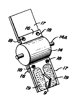
It will be noted that the striking tip or tip
separator 9 shown in Figure 6 is larger and the blades
17 are inherently longer than the tips 9 shown in
~igure 7 where the rotor 14 is relatively smaller than
the broadly corresponding rotor 14 shown in Figure 7.
This is merely to illustrate that the relative
dimensions of sharp tip 9 are not critical.
The important factor rather is that the sharp point
be positioned in the center of the blade and that it
be moved or rotated at a linear or circumferential
speed of between about 1760 feet per minute to 3700
feet per minute, which is the striking s~eed of the
sharp point and the side of the fluorescent tube
fracturing such tube and tending to break it into equal
sized pieces.
The blades 17 as shown in Figures 6 and 7
` are replaceable blades fastened by screw- or bolt-type
fastenings 18 to stub blade 16 welded directly to a
central rotatable drum 14 which has stub shafts 14a
welded or otherwise secured on both ends for mountina in
a fracture chamber 11 as shown in Figures 5.
It has been found that as the drum 14 rotates
carrying the blades 17 about the fracture chamber, the
2~ sharp striking point 9 first contacts the electrical tip
or a portion of the glass tube of the fluorescent tube
frequently shattering the glass at the base of the tip
and separating the tip plus progressively fracturinq the
glass behind the tip.
The speed of the blades 17 within the fracture
chamber 17 is approximately 1760 to 3700 feet per minute
or more preferably 2400 to 3050, or even more preferably
2650 to 2800 feet per minute. At this striking speed,
the tip of the blade upon striking the glass portion of
the fluorescent tube causes the glass at the front cc
the ~ube to collapse, usually lnto two more or less
WO93~1~87 PCT/US92/05~8
~3~ - 18 -
equ~l sized glass sections of about one-quarter-inch in
dimension. These sections of glass in effect fold back
into the tube as the tip progresses and may be further
struck and propelled against the back of the tube where
they eventually strike the rear of the glass~nvelo~e.
Meanwhile, the flat surface of the striking blade 17
continues toward the fluorescent tube and eventually
stri~es the two sides of the tube which have not
immediately broken out. The sides of the tube being
pres~nted to the blade in an edgewise orientation rather
th~ with a side orientation, present a stronger, less
easily fractured section to the advancing blade.
The two side sections, of the tube, therefore, present a
considerably greater resistance to the blade and in fact
it is the sides of the blade which wear away or abrade
the quickest. For this reason, it is preferable for the
sides of the fracture blade to be hard faced by an
overlay of hard facing material such as tungsten-chrome,
chrome manganese and chrome vanadium ferrous hard facing
applied by a welding torch or the like. Alternatively,
the sides of the blade can have hard metal inserts
secured over an underlying common steel base or the
sides of the blade can be formed from the separate wear
r~sistant sections of blade material. Since the wear
upon the blade is quite uneven due to the configuration
of the tube section, it usually is not necessary or
desirable to form the entire blade from a hard
wear-resistant material. It may in some cases, however,
be advantageous to hard face the end or edges of the tip
point as well.
As the flat blade 17 strikes the side of the
fluorescent tube, the sides are in effect, folded upon
each other and usually end up in pieces more or less
equivalent to the size of the pieces broken out of the
front of the tube. As the striking or fracture blade 17
continues to turn the strikin~ polnt 17 aqain s~rlkes
W0~3/0~8$7 2 1 1 3 ~ ~ 2 PCT/US92/05~8
-- 19 -- ,
the back of the glass tube from which the sides have
~een broken away. Striking the rear of the tube with
the sharp striking point breaks the glass in the center
and it tends to fold backward along the sides of the
5 point similar to the ac~ion at the front of ~e tube.
The result is that the glass originally broken from the
tube is more uniform in size and in particular less very
small pieces of glass tend to be formed by uneven
fracturing which small pieces may tend to be carried
away entrained in the countercurrent stripping gas with
the small potentially toxic phosphor and other powders
clinging to the glass which it is the aim or the overall
process to separate from the glass.
Since the stri~ing blade is traveling at a
rather rapid velocity of 1760 to 3700 feet per minute or
in the usual sized blade about 850 revolutions per
minute and the glass also strikes the sides of the
fracture chamber, the primary broken pieces of glass are
usually refractured into somewhat smaller sized pieces
of about the size of a small fingernail or less before
they leave the fracture chamber. However, it has been
found that with the striking or fractur~ blade of the
invention, the uniformity of the final glass fragments
is much better and the percentage of small particles
that might be carried away with the stripping air is
much less.
The average size of the glass particles formed,
as distinguished from the uniformity of the size, has
been found to be principally a function of the speed of
the fracture blade. The preferred speed for operation
of the following separation process has been found
to be approximately 2650 to 2800 feet per minute or
less preferably about 2400 to 3050 feet per minute.
In general, the operation of the process when using
3~ the blade of the invention will be found to be
unsatisfactorv at tip speeds of less than 1760 feet per
W~93/OI~X7 PCT/US92/0~$
~ 20 -
minute or more than 3700 feet per minute.
The fracture blade of the invention is, as
explained above, used in ~ process and apparatus for
fracturing fluorescent tube and separating the phosphor
particles and mercury vapors from the fractured glass.
Figure 8 shows diagrammatically a side
elevation of a partially broken away depiction of the
fluorescent tube treatmen. apparatus of the inven~ion in
which it is preferred to use tne fracture blade of the
invention. An initial fracturing and separating device
or means 11 is provided with a rotating blaae 13 powered
by a motor 15. The rotating blade which is provided
with the striking points 9 or the invention is
positioned to rapidly strike the end of a fluorescent
tube, not shown, that is extended or passed
progressively down a feed chute 19. The rotating blade
13 is preferably rotated, as shown in Figure 1, counter-
clockwise so that the tube or glass envelope 17 is
struek downwardly, progressively breaking off small
chunks of the tube which at the same time shatter into
individual pieces of glass in the manner explained
above. These individual pieces of glass are thrown
against the side of the chamber. The shock of both the
initial fracturing and the later impact with the walls
21 of the fracture chamber 23, i.e. the upper portion
containing the fracture blade 13 of the fracturing and
separation device 11, causes the dust particulates
coating the inside of the glass envelope to be jarred
loose from the surface. These small dust particulates,
which are normally adhered to the inside of the
fluorescent tube by a suitable thin film of adhesive or
other suitable expedients, after jarrinq loose become
entrained in the air stream within the chamber, which
air stream or flow passes initially down the feed chute
3~ 19 alongside the fluorescent tubes into such chamber and
progresses through the fracture chamber 23 to the
WVg3/01887 PCT/US92/05~8
- - 21 ~
exhaust conduit or tube 25 which opens into the
fracturing and separating device 11 just below the
fracture chamber 23. A vacuum or suction is applied t~
the exhaust tube 25 from a suction or draft device
farther down the line, in this case through a_suction
fan 27, as shown at the right side of Figure 8, which
fan 27 discharges air drawn through such fan with a
forced draft directly into a massive activated carbon
or charcoal-type filter 29 also shown in Figure 8.
Alternatively, the fan 27 could be positioned beyond
the charcoal filter, particularly if it is desired to
minimize escape of internal gas through any leaks ln
the charcoal filter housing or the like.
Below the fracturing chamber 23 of the
fracturing and separating device 11 is positioned a
countercurrent flow chamber 31 havins a decreased
diameter lower end through which air is sucked upwardly
from the terminal opening 33 from a particulate
collection chamber 35 which may comprise a steel
hopper-type collector or any other type collector.
A top or lid 37 closes off the upper portion of the
hopper-type collector and in the embodiment shown also
supports the fracturing and separating device 11 or
means through the side walls 39 of the countercurrent
flow chamber 31.
Within the countercurrent flow chamber 31 in
Figure 8, there are provided a series of baffles or
jarring surfaces 65 shown extended from the side wall of
the countercurrent flow chamber 31. These baffles 65
are ?rovided with generally upwardly directed slanted
impact surfaces onto which the glass particulates drop
or are initially projected by the rotating blades 13 and
then bounce from the first to the second of such
surfaces. A tortuous passage extends down between the
baffles 65 for downward passage of ~he glass
particulates and upward passage of a str~pplng qas.
W~93~ $7 PCT/US92/05998
~ ~ ~ 22
Each impact of a fractured glass particulate with the
impact surfaces of the baffles 65 has been found to
dislodge additional powder and any other contaminants
from the surfaces of the fractured glass particulates
and to signiflcantly increase the separation between the
glass and the toxic powder particles. Between impact
surfaces, the glass particulates pass downwardly through
the countercurrent flow of stripping gas which r~moves
dislodged toxic particles and other particulates rrom
the immediate vicinity of the glass particulates and
carries them upwardlv into the suction or outlet
tube 25.
The fractured or broken glass particula~es,
after being fractured in the fracture chamber 23, .all
through the countercurrent flow chamber 31 and tnrough
the terminal orifice 33 into the collection chamber 35.
During their passage, essentially in a free fall
straight downwardly through the countercurrent flow
chamber 31, they are acted upon by upwardly flowinc
gases or air passing through the terminal orifice 33
from the collection chamber 35 into and through tne
countercurrent flow chamber 31 and into the vacuum or
suction conduit 25. As these upwardly moving gases pass
the downwardly falling glass particulates, passing
through the countercurrent flow chamber, they strip
residual toxic dust precipitates from the surface of the
glass particulates and carry them upwardly to the inlet
of the suction tube 25 through which such powders and
gases are exhausted to subsequent filter apparatus to be
aescribed. The velocity of the upwardly flowing gas
through the countercurrent flow chamber 31 may desirably
be about 7200 feet per minute. Less desirably, the aas
velocity may be about 6000 to 9000 feet per minute.
In all cases, the velocity of the gas passing upwardly
through the countercurrent flow chamber 31 should ~e
sufficient to strip away any loose p~wder adherlng to
WO93/01887 PCT/US92/0~8
- ~3 ? 3 l3 63 2
the glass particulates and carry it upwardly to and out
the exhaust conduit 25, but insufficient to carry
upwardly any significant quantity of glass particulates.
As ~ill be understood, the glass particulates
are, in the embodiment of the invention shown in Figure
1, interrupted in their fall through the countercurrent
flow chamber by impacting upon the impact surfaces of
the baffles 65. The first such interruption is a~ the
top of the countercurrent flow chamber 31 just after the
glass particulates exit from the fracture chamber 23.
At this poin , many of the particulates are still
traveling with residual velocity obtained from impact
with the fracture blade 13. The second interruption
is just below the first impact surface after the
15 particulates are deflected to the next impact surface
and the fourth and last interruption is at the bottom of
the countercurrent chamber where the glass particulates
strike the last baffle 65 just prior to leaving the
tortuous passage 68 via the exit orifice 33 after having
20 bounced from one impact surface to the next, down
through the countercurrent stripping chamber. Impact of
the glass particulates with the impact surfaces of the
baffles 65 leads to vibration of the glass particulates
and this vibration, as well as the original shock of
impact, tends to crack off or loosen powder from the
surfaces of such particulates, which powder is then
stripped from the surface by the rapid countercurrent
flow air stream.
It will be seen in Figure 8 that the descending
gas or air passing through the fracturing chamber 23,
the passage of which gas is substantially aided by the
counterclockwise rotation of the fracture blade 13,
meets the upwardly passing gas or air flowlng through
the countercurrent flow chamber at the outlet to the
suction conduit 25 and both air or gas streams there
merge and pass into the conduit 25.
W093~01887 PCT/US92/05~
~ 3 ~ - 24 -
As will be seen from the drawing in Figure 8,
it is physically impossible for the glass particulates
to progress in a straight line through the passage 68 so
that the glass particulates must, in effect, drop from
one surface to the next, each time jarring and shaking
the particulates and causing dislodgment of toxic powder
from the surface of the glass particulates. The
distance of the jarring surfaces from each other should
be sufficient to allow sufficient acceleration of the
glass particulates as they fall from jarring surface to
jarring surface to disloage powder from the surface of
the glass particulates, but insufficient to cause
additional fracturing of the glass. It is undesirable
for the glass particulates to be broken into too small
particles else they may also be entrained in the
countercurrent gas stream and removed with the toxic
powder rather than with the larger glass particulates.
As indicated above the fracture blade of the invention
considerably advances such aim.
The fractured glass particulates, after having
passed through the tortuous passage 68 pass through
_he opening 33 at the bottom of the tortuous passage
and fall into the particulate collection chamber 35.
Such particulate collection chamber 35 has a
substantially conical or slanted bottom 41 against
which the fractured glass particulates 42 collect.
Extending into such bottom from one side at an angle is
an auger-type screw conveyor or mixer 43 having an outer
casing 45 and an inner auger 47. The casin~ 45 is open
at the bottom and the auger extends partially from such
casing into the mound of fractured glass particulates
that has collected upon the bottom 41 of the collection
chamber 35. As the auger or spiral screw conveyor
turns, the fractured glass particulates are drawn into
the spiral conveyor, and as the conveyor rotates,
such particulates are carrled upwardly in the conveyor.
W~93/0~887 2 1 1 3 ~ 3 2 PCT/US92/0~998
- 25 -
Since the auger is continuously turning and forcing the
fractured particulates upwardly, there is a considerable
continuous agitation of the particulates with a
continuous overturning of the particulates collected
within each spiral of the auger with the result that
the various particulates are rubbed continuously against
each other abrading toxic powder on the original
surfaces from such surfaces. Such loosened or freed
toxic powder particulates being considerably smaller
than the fractured glass particulates tend, due to the
general agitation of the column of glass particulates ir
the auger, to work their way back down the auger while
the glass particulates are carried upwardly and
discharged at the top down the discharge chute 51 into
a collection chamber 53 where the glass particulates
may pass through a screen or more preferably, a grizzly
55 which separates out the larger tips or metal
electrodes from the ends of the tubes which electrodes
are deposited in the separate section 53A of the
collection chamber.
The toxic powder material 56, which wor~s its
way back down the rotary auger, collects at the bottom
and may be allowed to pass through small openings 57,
too small for the passage of fractured glass
particulates, in the bottom into a storage chamber 59
below the collection chamber 35. A helical screw-type
transporter 61 extends into the storage chamber and may
be used to remove the toxic powder for disposal or
recovery. Such removal may be either continuous or
periodic as necessary.
Alternatively, it has been found that since
not a great deal of toxic powder collects at the bottom
of the rotary screw auger 47, that such powder may
merely be allowed to build up or collect at the bottom
of the auger 47 and may be merely cleaned out durlnq
down time of the apparatus by a vacuum hose or even
W093/01887 PCT/US92/05998
3~ f.
- 26 -
manual shovellng through a trap or opening in the side
of the ~ottom of the collection chamber 35 or bott~m of
the auger casing 45.
While a large percentage of the toxic powder,
because of its small size, works its way back down the
helical screw conveyor 47 because of its relatively
small size and reaches storaqe chamber 59, some of the
toxic powder is also carried up the auger 43 with the
fractured glass particulates and is discharged down
discharge chute 51 with the fractured glass -
particulates. This toxic powder, after having passed
through the abrasion aevice, i.e. the rotary auger 43,
will have been largely abraded, however, from the
surface of the fractured glass particulates.
As a result of an air inlet 63 in the side of
the collection chamber 53 and interconnections 70 and 69
between the upper portions of the auger 43 and the
particulate collection chamber 35, as well as a separate
air or gas take-off conduit 111 at the top of the auger
43 connecting with the main stripping gas conduit 25,
air is drawn rapidly up the discharge chute 51
countercurrent with the descending fractured glass
material and small particles of toxic powder which,
as a result of abrasion between the fractured glass
particulates, have all been effectively removed
from the surface of the fractured glass particulates.
The air passage up the conduit 51 is sufficiently fast
to carry all loose powdex up the chute 51 and into the
top of the auger where, because it is already entrained
in the rapidly moving air, it is withdrawn with the air
stream passing through the conduit 111 via off-take
conduit 24 into a centrifugal separator 71 and also to
some extent via conduits 70 and 69 into the collection
chamber 35 where it eventually joins the countercurrent
3 5 f low of air upwardly through the tortuous passage 68.
This countercurrent stream of air, as explained aDove,
W~93~01887 PCT/US92~0~8
- 27 _ ~ 6~
joins the concurrent stream of air passing down the
chute 19 and through the fracture chamber 23 and is
drawn off through the off-take conduit 25.
Two streams of gas or air pass into the initial
portion of conduit 25, the one from the top,~ing f~irly
well saturated with small particulates separated from
the fractured glass particulates in the fracture ~hamber
23 and the one from the bottom issuing from the tortuous
passage 68 being much cleaner countercurrent stripping
gas. ~owever, the gas stream from tortuous passage 68
also carries, by the time it has traversed ?assage 68,
considerable toxic powder. This toxic dust ca~rying air
passing into the exhaust or off-take condu;t 25, located
just under the upper baffle 65, joins air passing from
1~ conduit 111 and then passes from conduit 25 to a
cyclone-type gas separator 71 where a swirling motion
is set up in the air stream by the angle of the gas
entering from the side. Such swirling motion combined
with the increase in the volume of the passage, as
generally known to those s~illed in the art, causes the
upper range of the small particulates entrained in the
gas to move outwardly in the gas stream and to separate
from the gas stream against the side of the cyclone
apparatus and fall along the side wall to the bottom of
the cyclone separator where the particulates can be
periodically allowed to pass by gravity from the bottom
of the cyclone into any suitable receptacle, not shown.
The gas from which the particulates have
separated largely by having been thrown against the
sides of the cyclone chamber 73 by the spiraling action
of the gas, meanwhile fills the center of the chamber
and wells or passes upwardly from the chamber through a
central dependent conduit 75, the shape of the outer
surfaces of which serves initially also to aid ln
3~ initiating the swirling motion of the gas Dasslng ln~o
the cyclone device. The upwelling gas passes ~hrou~h
~3~ 3 PCT/US92/O5~fi
- 28 -
the conduit 75 into an upper chamber 77 from which
it is exhausted through a further conduit 79 into the
lower portion of a bag-house-type filter 81 where the
air stream is filtered by conventional periodically
vibrated filter bags 83. The filter bags ~f~ect a good
separation between the air and toxic powder entrained in
the air. The filter air is collected in the top of the
bag-house-type filter 81 into the chamber 85 from whence
it is discharged via conduit 87 to the top of a filter
chamber 89. Within the top of the filter chamber 89
there is preferably a high efficiency HEPA-type filter
93 for removing very fine particulates from the air
stream. The HEPA filter 93 is provided with an outlet
95 which leads from the filter chamber 89 to the suction
fan 27 previously identified. This fan 27 is operated
or rotated by a motor 97 and exhausts from an outlet 99
which opens into the approximate center of the activated
carbon or charcoal filter 29 previously identified.
The activated carbon or charcoal filter 29 is
shown formed of a central chamber 101 within the center
of a series of flat activated carbon panels 103 usually
two or more inches thick. Each panel is preferably
formed of two separate panels a short distance apart
designated 103A and 103B. The panels are fitted
2~ together so that an essentially gas tight chamber is
formed having a fairly large central opening and outer
walls formed of double carbon panels through which gas
entering the central chamber and spreading out through
the chamber slowly passes while metallic vapors such as
mercury vapor in the gas are absorbed into the activated
carbon. The large volume of the central chamber 101 and
the large area of the activated carbon panels 103
surrounding the central chamber ensure that the gas
velocity is slowed down sufficiently to allow sufficient
retention time in the activated carbon panels 103 to
absorb the metallic vapors in or upon the chemically
WO93/0188~ 2 1 1 3 & 3 ~ PCT/US92/0599g
- 29
coa~ed activated carbon or charcoal. After the carbon
panels are partially saturated with metallic vapor, the
panels 32 are changed to renew the absorption capacity
of the carbon filter panels.
It has been found that when the fra~ture blade
of the invention as shown in Figures 4, 6 and 7 is used
with the fracture and separation apparatus shown in
Figure 8 that a very superior separation of glass
particulates and potentially toxic phosphor and other
powaers is obtained. The more uniform fractured glass
sizes and absence of any great amount of very small
glass particles enables a very clean separation to be
effected.
Furthermore, when the blade of the invention is
operated at the speed of the invention, i.e. within the
range of 1760 to 3700 feet per minute tip speed, or
striking tip speed, it has been found that a very
superior fractured glass mix is produced upon which a
particularly effective separation of the toxic phosphor
particles and glass particulates can be effected.
Operation over this tip speed tends to produce glass
particulates having an average size which is undesirablv
small and operation below such speed tends to produce an
average size of glass particulates which is undesirably
large.
It should be understood that although the
present invention has been described at some length and
in considerable detail and with some particularity with
regard to several embodiments in connection with the
accompanying figures and description, all such
description and showing is to be considered to be
illustrative only and the invention is not intended to
be narrowly interpreted in connection therewith or
limited to any such particulars or embodiments, but
should be interpreted broadly within the scope of the
delineation of the invention set forth ln the
WO93/01~87 ~6~ PCT/US92/05998
- 30 -
accompanying claims thereby to effectively encompass the
intended scope of the invention.