Note : Les descriptions sont présentées dans la langue officielle dans laquelle elles ont été soumises.
CA 02114521 2002-06-13
- 1 -
DUAL-TEMPERATURE HEAT PUMP APPARATUS AND SYSTEM
Background of the Invention
Systems for taking advantage of complex compound
technology comprising solid-vapor compositions formed by
adsorption of gas molecules on a solid adsorbent are known.
Heat pump systems incorporating reactors provided with
complex compounds provide significant advantages over
conventional heat pump systems used for residential and
commercial space conditioning, industrial heat pumping and
refrigeration in view of high temperature lift created by
the solid-vapor media as compared to other sorption media.
The complex compound based systems can eliminate the need
for cooling towers, lift staging, and require few, if any,
moving parts. Such systems also obviate the use of
objectionable CFCs.
The solid-vapor compounds suitable for heat pumps
include complex compounds comprising materials which adsorb
molecules of a polar refrigerant gas to form coordinative
bonds in which the gaseous reactant coordinates via
electron displacement with a solid adsorbent, commonly a
solid metal inorganic salt. The adsorption/desorption
process releases significant heat during adsorption, and
adsorbs energy during the desorption phase. A number of
useful complex compounds and systems are disclosed in U.S.
Patents 4,822,391 and 4,848,944.
There is a need for complex compound heat pump systems
having the capability of simultaneously producing heat,
primarily in the form of hot water or steam, and
refrigeration. For example, in the food processing
industry, hot water, a heat transfer fluid or steam is used
in washing and cleaning operations, while other operations
performed at the same time, in the same plant, require
cooling and/or refrigeration. It is to an apparatus and
system that is capable of simultaneously producing such hot
CA 02114521 2002-06-13
- 2 -
fluid and cooling and/or refrigeration, that the present
invention is directed.
Summary of the Invention
An apparatus and system of the present invention using
complex compound heat pump technology provides a system for
simultaneously producing hot water and refrigeration. The
invention incorporates an apparatus having a pair of
reactors using a single stage cycle incorporating a gaseous
refrigerant, preferably ammonia or water, in a phase change
embodiment. The alternate adsorption and desorption of the
ammonia with the complex compound is cycled such that one
reactor is in an adsorption phase while the other reactor
is in the desorption phase. In addition to a condenser for
the ammonia refrigerant, preferred apparatus embodiments
include other heat exchange means for taking advantage of
heat transfer between the desorbed refrigerant gas and the
heat transfer fluid, for example, the industrial plant
water, which is to be heated by the apparatus. The system
of the invention may also be advantageously used for dual-
temperature thermal storage, as will be further described
hereinafter.
According to an aspect of the present invention, there
is provided apparatus for simultaneously supplying heating
and cooling or refrigeration, comprising:
first and second reactors, each containing a reactant
comprising a complex compound of a metal salt selected from
the group consisting of a metal oxide, halide, nitrate,
nitrite, sulfate, oxalate and sulfide and mixtures and
compounds thereof, wherein the metal is selected from the
group consisting of alkali metal, alkaline earth metal,
transition metal, aluminum, zinc, cadmium and tin, and a
gaseous refrigerant adsorbed thereon selected from the
group consisting of ammonia, water, sulfur dioxide, lower
CA 02114521 2002-06-13
- 2a -
alkanol, alkanolamine, polyamine and phosphine, or a metal
carbonate comprising a reaction product of said metal oxide
and carbon dioxide gaseous refrigerant,
a condenser for condensing said gaseous refrigerant,
a first refrigerant conduit assembly for directing
said gaseous refrigerant alternately to said first and
second reactors, respectively, a second refrigerant
conduits assembly for directing gaseous refrigerant
alternately from said first and second reactors,
respectively, to said condenser, and a third refrigerant
conduit assembly for directing condensed gaseous
refrigerant from said condenser to refrigerant condensate
receiving means,
heating means for heating said complex compound or
said metal carbonate alternately in said first and second
reactors, respectively, and heat extraction means including
a first heat exchanger for providing heat exchange
communication between said condenser and said first and
second reactors for extracting heat from said complex
compounds carbonate alternately in said first and second
reactors, respectively, and
a first fluid conduit assembly for directing a heat
transfer fluid in heat exchange communication with said
condenser and said heat extraction means whereby said heat
transfer fluid becomes heated by said heat exchange
communication, and a second fluid conduit assembly for
directing said heated heat transfer fluid from said
condenser to receiving means therefor.
CA 02114521 2002-06-13
- 2b -
Brief Description of the Drawings
Figs. 1 and 2 illustrate a single-stage complex
compound heat pump cycle of the type used in the apparatus
of the invention; and
Fig. 3 illustrates schematically a preferred heat pump
apparatus of the invention;
Fig. 4 is a schematic illustration of another
embodiment of the invention; and
Fig. 5 illustrates a use of an apparatus of the
invention with a turbine apparatus.
Detailed Description
In Fig. 1, a schematic representation of two reactors,
A and B, combined with a condenser and evaporator for
treating the refrigerant vapor is shown. A temperature
pressure diagram for ammonia and a single complex compound
used in both reactors A and B is also shown. In a
chemisorbtion reaction in which the refrigerant gas,
ammonia, is alternately adsorbed and desorbed from the
complex compound located in the reactors, the reaction
cycle is as follows:
WO 93/0S349 PCT/U~92/05259
r -.. ..1 -1
",; ~ ~ -~1 ,
_3_
In phase 1-2 between state points 1 and 2, complex
compound in reactor A is heated to temperature T3 with either
prime energy or high temperature waste heat, resulting in
refrigerant vapor pressure higher than the pressure of the
refrigerant at the delivery temperature T2. Complex A
undergoes an endothermic desorption reaction releasing ammonia
which is condensed at delivery temperature T2, releasing
energy.
In phase 2-3, ammonia is condensed at point 2 and
~yp~.cally throttled to a lows= pressure and evaporated at
temperature T~ (point 3). Energy absorbed at T~ represents
waste heat recovery or useful refrigeration, depending on the
aPp~ication.
At phase 3-4 , the complex compound in reactor A is at, or
slightly above; heat delivery temperature, whereby the vapor
pressure of the cAm~lex compound is less than the vapor
pressure of the refrigerant at refrigeration or heat recovery
temperature, causing the refrigerant to evaporate at T~, which
is then adsorbed into the salt in reactor B at T2. The
adsorption reaction is' exothermic, releasing heat to the
industrial process.
In phase 4-1, tie complex compound is heated by the prime
heat source to temperature T3. A portie~n of this heat may be
supplied from a phase shifted second sub-system or from the ,
same sub-system reactor A tobe cooled toward temperature T2.
The apparatus of the invention incorporates two comglex
compound reactors and operates in two main sequential time
periods, all of the cycles occurring in each pf the sequences
ar time periods. lne reactor desorbs refrigerant in an
endothermic xeactionwhile the other reactor adsorbs
refrigerant in an exothermic reaction. In a basic apparatus
for simultan~ously.providins~ heated heat transfer fluid and
cold refrigerant; for example water and ammonia, respectively,
refrigerant desorbed from a first reactor is directed to a
condenser where it is cooled, and ~h~n recovered for cooling
or ref~igeratian. Typically, the condensed refrigerant is
directed 'to the evaporator of an existing refrigeration system
W~ 93105349 PC f/US92/05259
,; . 't
> ~' ~ ;;:i j
,~ _ .>. ,. ~... :,~ _
to provide cooling, and the gaseous refrigerant returned to an
adsorbing reactor. Simultaneously, water to be heated is
directed to the condenser and the exothermic reaction in the
adsorbing reactor. The sequential exposure for heating water
in the condenser and adsorbing reactor will depend on the
relative operating temperatures of those components with
exposure first to the lower temperature component. At the end
of a cycle, the functions of each reactor are reversed, i.e.,
interchanged.
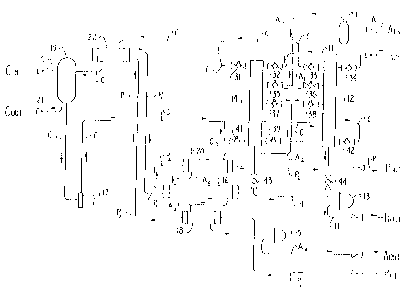
1p Referring to Fa:g:- 3, a pair of reactors 12 and 14 are
provided with a,rea~ctant, preferably a complex compound. For
the discussion hereinafter, it will be assumed that the
g~as~ous refrigerantvwhich is alternately adsorbed and desorbed
on the salt or complex compound, is ammonia. Other useful
gaseous refrigerants and the scope of the metal salts used to
form the reactants or complex compounds will be described
further hereinafter: Although the heat transfer fluid
directed to and from the react~rs, and recovered as a heated
fluid may sometimes ~e referred to hereinafter as water, it is
20' to be understood that any suitable heat transfer fluid may be
used; for example, steam; water glycol mixtures, oils,
alcohols, as well as refrigerants, such as ammonia. 7Cn
addition to the two reactors 12 and 14, the necessary
components include a condenser Z6 for treating the desorbed
gaseous refrigerant by cooing it with, for example,
relatively cool industrial plant water, which itself becomes
heated in'the beat exchange: The condensed ammonia is then
useful to provide co~ling or refrigeration, while the heated
waber is useful for plant processing operata:ons.
Tn, the preferred agparatus embodiment illustrated, an
ammonia~liquid subcooler 1S and/or an ammonia vapor heat
exchanger, referred to as a desuperheater 20, _are.provided.
In additaon, a preferred apparatus includes a water/water heat
exchanger 22, an expansion tank 19 for add~,ng make-up water
for cooling the reactors during adsorption, an ammonia suction
trap 1l, a steam trap 13, and a float valve 15 ammonia vapor
trap). The water/water heat exchanger 22 shown in the
W~ 93105319 ~~ s. ~_ j ~ 3 ;) _~ PCT/US92/OS259
-5-
specific apparatus embodiment is used for recovering heat from
the exothermic adsorption reactions. Such a heat exchanger is
optional, and instead the water, or other heat exchange fluid
to be heated in the process, may be directed through the
adsorbing reactor to pick up heat directly from the reaction.
However, where recovery of potable water is of importance, the
use of such a heat exchanger may be advantageous.
The operation of the preferred embodiment heat pump of
Fig. 3 is as follows. In a first phase, the complex compound
1p in reactor l2 is desorbed by providing hot water or steam or
other heat transfer fluid, from the plant into lane H at H;n,
with valves 34 and ~4 open. The heat exchange design of
r-eactor 22 allows the heat from the hot water and/or steam to
heat the complex compound in the reactor, increasing the
ligand vapor pressure and causing the complex compound to
undergo an endothermic desorption reaction, releasing ammonia
vapor. At the same time, relatively cool or ambient
temperature plant water, for example at 8a°F, is directed into
pipe P at Pp~. The desorbed ammonia released from reactor 12
is sequentially directed through e~pen valve 38 via conduit A
from the reactor sequentially through desuperheater 20,
condenser 16 and liquid subcooler 18. Each of these
components acts as ~ heat exchanger, and is provided with heat
exchange means theranally communicating the desorbed ammonia
with plant water which successively passes thr~ugh subcooler
18 , heat exc:har~ger 2 2 , cpndenser 16 and desuperheater 2 0 . In
than manner, the hod ammonia vapor desorbed from reactor 12 is
cooled as as successively exchanges thermal energy with the
plant watero which in turn is heated in the aforesaid
components.
The relatively cool plant water is first thermally
contacted with the aonaensed ammonia in liquid.~subcooler ~.8,
thereby further coolang the ammonia and causing the plant
wader to become initially heated a The plant water is then
directed to water/water heat exchanger 22 where it becomes
additionally heated by thermal communication with heated water
PCT/US92/05259
VY~ 93/05349 a ~ , .~
J iv/ ..1
s~~
from the adsorbing reactors. Thereafter, the plant water is
directed from the heat exchanger 22 to condenser 16, picking
up additional heat from ammonia condensation and then to the
desuperheater 20 for communicating thermally with the
relatively hot ammonia vapor arriving from desorption reactor
12: The resulting heated water, for example at 130°F, is then
directed along pipe P to Pit, where it is then directed for
use in the plant as'desired or needed. As previously noted,
the sequence of components for water heating will depend on
their relative operating temperatures, with water directed
through successively higher temperature components. In the
example shown, with the condenser operated at a higher
temperature than'the adsorbing reactors, water heat exchange
takes place with the adsorbing reactor heat at heat exchanger
22 prior to heating in: the condenser. Aowever, in other
systems, the adsorbing reaction temperature may be higher than
the condenser temperature in which'event, the sequence would
be modified: An additional: heat exchanger referred to as a
trim'heater, (not shown) may optionally be provided to further
heat water downstream from desu,perheater 20. Feat introduced
to such 'a device may b~ from a steam or hot ammonia vapor
line. The ammonia condansat~e from liquid subcooler 18 is
directed via pipe H through high side float valve 15 thraugh
A out to the plant high pressure receiver where it is used for
plank c4oling or refrigeration operations. For example, the
condensed or cold refrigerant is directed to are evapara~or
which may be part of'an existing refra.geration system, or to
other evaporator or heat exchanger receiving means:
Concurrently with the ammonia desorption in reactor 22,
' ammonia is adsorbed in reactor 14 with ammonia supplied via
conduit A at Ann via a suction trap 11, through open valve 35
and into reactor 14v In this phases valves 36 and 37 are
closed, as is valve 3~. Hot water inlet valve 32 and outlet
valve 43 are also closed while heat transfer water from pipe
C at C~~, via expansion tank 1~, ie pumped by water pump 17
i~~o reacto~° 14 via open valve 41'. Water inlet 42 for reactor
r n i ~..~a ar a r,~ ~...,'
... .._....r..,. '.~''~ .. ..., ~ .t ~~~. .. . s o.,~, ...~..y... . , . ~ ,
'.. .,
WO 93/05349 ~ PCTl~JS92/t?5259
~ .~ i ' G
i i .y ' Y ';~ '
a
_7_
12 is also closed. Water directed through the reactors in
heat exchange communication with the complex compound in
reactor 14 is thus circulated via pipe C and directed from
reactor 14 via outlet valve 31 to heat exchanger 22. Because
the adsorption reaction occurring in reactor 14 is exothermic,
the heat transfer water extracts heat from the reactor by heat
exchange exposure, and thus will be warmed relative to the
temperature of the plant water directed to heat exchanger 22.
The plant water will be heated and the cooling heat transfer
water somewhat cooled by this advantageous heat exchange
communication.
Once the complex compound in reactor z2 has been
substantially desorbed; i.e., is substantially depleted of
ammonia, and the complex compound in reactor 14 is
substantially saturated with ammonia, the reactors are
reversed, whereby reactor 14 becomes the desorbing reactor and
reactor 1.2 the adsorbing reactor. Prior to beginning the
reverse cycle, a transition period or interval is provided by
opening valve 39 which allows steam in reactor 12 to expand
and drive remaining heat transfer water from reactor 14. Such
an interval between cycles is highly desirable to avoid
cavitation in the reactors. In addition, because the
desorbing reactor is relatively hot as compared to the
ads~rbing react~r, it may be advantageous to direct the
relatively hot heat transfer fl.uad from the desorbed reactor
to the adsorbed reactor, which now becomes the desorbing
reactor and requires heat.to drive the reaction. Thereafter,
the valve ~9 is closed, and the ~revfously described open
valves are closed and the closed valves opened, whereby hot
water and/or steam via~conduit H is directed into and through
reactor 14: The heated complex Compound in reactor 1.4 desorbs ;
ammonia, which is then sequentially directed via open valve 37
through heat exchanger 20, condenser 16 and liquid subcooler
~,g, and condensed ammonia recovered at Apt. Simultaneously,
plant water via pipe P is continu~usly heated as previously
described in the ffirst cycle, and recovered via Pit.
Although a number of components of the apparatus shown in
~ CA 02114521 2002-06-13
Fig. 3 are preferred, the liquid subcooler and
desuperheater are optional, as are the ammonia suction
trap, steam trap, expansion tank and water/water heat
exchanger. However, such components contribute to improving
the efficiency of the system and providing substantially
greater temperature spreads between water introduced and
recovered. The valves illustrated may also be substituted
with four-way valves cooperating with control and switching
means for directing heating water and cooling water as well
as ammonia to and from the reactors. Moreover, the ammonia
flow control valves 35, 36, 37 and 38 may be one-way check
valves. Means may also be provided for circulating heat
transfer fluid between the reactors during the previously
described transition period, between cycles, to recover
sensible heat thereby further improving the overall process
efficiency.
The substantially continuous generation and recovery
of hot water and condensed ammonia may be directed to
receiving means respectively and used as needed and
desired. The ammonia may be directed to a refrigeration
system, into a high pressure receiver and used to provide
refrigeration for any desired cooling or refrigeration
processing needed.
Specific metal salts used to form complex compounds
useful in the apparatus and systems of the invention
include metal oxides, halides, carbonates, nitrites,
nitrates, oxalates, sulfides and sulfates and chemical
compounds, for example, double salts, and combination of
salts and compounds as well as eutectic and peritectic
mixtures thereof. Suitable double salt compounds are
disclosed in U.S. Patent No. 4,848,994. Preferred metals
are selected from alkali and alkaline earth metals,
transition metals, aluminum, zinc, cadmium and tin.
CA 02114521 2002-06-13
- 8a -
Polar gaseous refrigerants or reactants which are
adsorbed on the solids to form the complex compounds, and
which are especially useful in the invention, are ammonia,
water, methylamine and methanol. Ammonia is especially
preferred because it is stable and forms high energy
complexes. However, sulfur dioxide, other lower alkanols,
WO 93/D5349 ~r ~~. %_ ~ ~ ;~ _~ PCT/U~92/Q5259
_g_
pyridine, alkylamines and phosphine may also be used. Carbon
dioxide may also be reacted with metal oxides to form metal
carbonates.
Particularly preferred systems incorporate the following
complex compoundsa (a) caCl2 ~ 4-8 (NH3) (b) CaCl2 ~ 2-4 (NH3) ,
(c) SrCl2 ~ 1-8 (NHS? , (d) SrBr2 , 0-8 (NH3) , (e) CaHr2 ~ 2-6
(NH3) , ( f) cocl2 ~ 2-s (NHS) , (g) Nicla ~ 2-s (NH3) , (h) Fecl2
~ z-s (NH3) / and (~) NaHF4 ~ 005-2.5 (NHS) .
Although in the aforesaid complex compounds, numerical
values o~ moles of ammonia per mole of salt are given, in some
complexes, the male range comprises several coordination
steps. TP~us, for example, in the case of NaBF~, a number of
different neighboring reaction steps occur between the
numerical limits given. Typically, however, practical
considerations only allow for use of a portion of the design
coordination range, and thus the ranges are intended to be
approximate, as will be understood by those skilled in the
art:
Another embodiment of the apparatus and system of the
invention for providing simultaneous dual-temperature results
comprises a pair of rectors mach having a different complex
compaund with the polar refrigerant, such as water or ammonia
cycled between'~the two reactors in alternate adsorption and
desorption, to create simultaneous heating and cooling. In
ouch an embodiment, rather than directing the refrigerant to
phase change components, i.e., a condenser as described in the
previous embodiment; the heating and cooling is achieved by
heat exchange in the reactors themselves during the adsorption
and desorption re~Gtions;
In Fig. 4, there is schematically illustrated an
apparatus comprising reactors 50 and s~, each having a
different acorn~r~ia-salt c~mplex, or other .suitable polar
refrigerant-salt complex as well as metal oxide and carbon
dioxide reactions to foxm metal carbonate reactants. In this
embodiment, it a.s also important that the different complex
compounds or reactants in the respective reactors have
WO 93/05349 PC'T/US92/05259
,t
.., . .~. ~ -) ,.., .~
-10-
substantially different equilibrium temperatures, preferably
a differential of between about 20°C and about 150°G. The
term "equilibrium temperature differential" is intended to
mean the difference between any two different complex compound
equilibrium temperatures at the same or substantially the same
operating pressure, typically between about 0.1 and about 50
bars. Such an equilibrium temperature differential provides
sufficient practical temperature lift and yet within the
practical and safe ranges for heat rejection during exothermic
ammonia adsorption.
In one reactor, a preferred complex compound as
previously described is present, here~.n referred to as group
A; while in the other reactor, a different preferred complex
compound, referred' to as Group B, is BaCl2 ~ 0-8 (NH3) , CaCl2
~ 4-8 (NH~) , CaCl~ ~ 2-4 (NH3) , SrCl~ ~ ~-8 (NH3) and NaBF4
0.5-2.5 (NH3). Preferred pairing of a Group B reactant with
an above-described group A reactant is as follows:
~ ~. '~ =) :'; .t
'!~(> 93f05349 PC'f/LJ~92i(~5259
-11-
Grout B Group A
BaCl2 ~ 0-8 (NHS) (~) - (i)
CaClz ~ 4-8 (NH3) (d) - (i)
CaCl2 ~ 2-~ (NH3) (d) - (i)
SrCl2 ~ 1-8 (NH3) (e) - (i)
NaBf4 s 0:5-2.5 (NH3) (a) - (h)
Each of the reactors is provided with heat exchange means
through which a useful and practical heat exchange fluid,
1~ i.e., water, glycol water, etc:, is directed during the
reaction. In the apparatus embodiment shown, reactor 50 is
the high temperature reactor to be heated to desorb
refrigerant at high temperature and adsorb at a mid~range~
temperature, while reactor 60, the cooler temperature reactor,
adsorbs at a mid-range temperature and desorbs at low
temperature to pro~ride cooling or refrigeration. To obtain
simultaneous or continuous heating and cooling, pairs of these
twb salt reactors will be used and operated in opposing or
reverse cycies respectively. With reactar 5~ adsorbing,
water, typically at a temperature of bet~reen about 35°F and
about 25d°F; introduced into the reactor via inlet conduit
51' becomes heated by heat exchanger exposure to the
exothermic adsorption reaction-process and is recovered via
owlet pipe 55: At: the same tizns, because of the equilibrium
pressure difference be'~ween the campounds in the respective
reactors, the ~ompleac c~mpvund in rector 60 desorbs ammonia
which is suctiohed to adsorbing rector 50 via pipe 59~. The
heat transfer fluid supplied to deforming react~~° 50 via pipe
56 gives up heat and becomes cooled by heat exchange exposure
to the endott~erm1c desoz~bing 'reaction and may be recovered via
pipe 57. Such flu~.d may ~e used directly in plant prdcessia~g,
or it may be used for 3.ndi~ect heat transfer with a plaint
refrigerate.~n system, f~r ea~amplea in a heat exchanger for
providing cooling in the plant. ~gair~, such a fluid may be
~5 wager, water glycol mixtures, alcohols, or ammonia or other
suitable fl~.id ar refrigerant.
W~ 93/05349 PCT/US92/05259
:; fs. .i_ ~.,~ ~~ .~ -12 --
At the end of the cycle with the complex compound in
reactor 50 being substantially saturated with ammonia, or
other polar refrigerant, and the complex compound in reactor
60 being substantially depleted of the refrigerant, the cycles
are reversed, with reactor 50 becoming the desorption reactor
and reactor 60 becoming the adsorption reactor. Prime energy
is supplied to reactor 50, for example with steam via pipe 51,
to bring the complex compound to a high temperature for
desorbing. ammonia which is directed to adsorbing reactor 60
via line 54. Energy recovery from this cycle is primarily
from adsorption reaction heat transfer to heat transfer fluid
in reactor 60. If desired, some additional heating of the
hgat transfer fluid may be carried out in a desuperheater 52
by heat exchange with high temperature ammonia from desorbing
reactor 50 via conduit 62, which is then directed to reactor
60 via conduit 62, instead of line 54. The heated fluid may
be recovered via outlet line 71 for use.
Refrigerant supply conduits 63 and 65 to the reactors may
also be provided. The reactors may also be provided with
supplemental heating means, for example, electrical resistance
heaters exhaust ga , steam, or heat from any other suitable
or available sAUr~e ' for heat~.ng the complex compound during
desorption: It may be preferred to combine pairs of the two
different salt reactors with reactor pairs operated in
alternating phases to provide more efficient continuous
hewing and cooling. Such reactor systems may also
advantageously incorporate additional heat exchange means for
taking advantage of 'the different ammonia (or other
refrigerant) and heat transfer fluid temperatures recovered
3~ from the reactors, as well as to provide heating to the
reactors for desorption, where appropriate br advantageous for
~,mproved performance and efficiency.
Fig. 5 illustrates an example of a use of the apparatus
of the invention in a system with a gas turbine. It will be
appreciated that gas turbine efficiency is substantially
improved where cool inlet air temperatures are grovided. For
example, it is highly advantageous to introduce cool air into
.r~ a r' .
pCT/US92/Q5259
VVO 93/05349
-13-
a gas turbine at temperature ranges of, for example, between
about 50°F and about -°40F, for substantially increasing the ,.,
power output, efficiency and capacity of the gas turbine to
generate electric power. A heat exchange means providing low
gas inlet temperatures utilizes, for example, a glycol water
heat exchange solution in a heat exchanger through which the
air passes. As the air is cooled, it becomes saturated with ,
water vapor, undesirable in the turbine. It is thus necessary
to warm the cooled air slightly to reduce its relative
humidity from abobt 100% to, for example, less than about 90% .
An apparatus of the invention which provides simultaneous
cooling and heating as previously described may be used gaits
advantageously tg provide coola.ng for the gas turbine inlet
air, and simultaneously pr~vide heat for slightly heating the
inlet air to reduce its relative humidity.
The schematic system of Fig: 5 illustrates the use of a
dual temperature apparatus 70 of the invention for providing
cold refrigerant (Fig. 3), or cold heat exchange fluid (Fig.
4) via candui.t 84 to air inlet cooler 76 for gas turbine 7g.
~ Heat exchange fluid or refrigerant circulated through cooler
76 is returned to the reactor system via line 82.
Simultaneously, hpt water or heat transfer fluid from
apparatus 70 may be directed via pipe 73 for heating the air
in heat exchanger 78' just before it enters the turbine. Tn
addition, hot exhaust gas from-the gas turbine 74 may be
advantageously used and directod aria conduit 77 to heat
exchanger 72 to provide heat for driving desorbing reactors in
apparatus 70. A fluid loop between the r~actor system and
heat exch~r~ger ?1 is also provided via pa:pes 77 and 79.
Fxcess:heat produced bythe reactor system may be disposed of
by directing it to heat rejeati~n means 72, for example, a
cooling tower,,air coil or evaporative cooler, via line 83,
which also may be tied to line 73 for providing the heat for
heat exchanger 78, as previously described. A return line 85
between heat rejection apparatus °72 and the reactor assembly
is also shown; and connected to return line 75. The type of
'dV0 93!05349 PC'1'/US92/05259
~? ;' :" ~~ s
-14-
heat exchangers 76 and 78 maybe of a direct contact, liquid
to air, type, or may be of an indirect type, for example, fin
and tube. If a glycol-water mixture, or similar cold
temperature water containing heat exchange liquid is used in
a direct contact air cooler heat exchanger, reject heat from
reactor assembly may also be used advantageously to lean out
or reduce water concentration in the liquid. Reactor reject
heat may also.be used to defrost an indirect type air cooler.
Turbine exhaust gas heat may also be used for driving water
from a hs~at exchange liquid and/or defrosting an air cooler.
Although the aforesaid embodiments have been directed
primarily to the recovery and immediate use of the recovered
condensed refrigerant and heated transfer fluid (first
embodiment), or the dual temperature recovery of the heat
transfer fluid (Fig. 4 embodiment), these apparatus may also
be used for pr~viding thermal storage. Thus, rather than
immediately using the condensed or adsorbed ammonia or other
refrigerant for plant cooling or refrigeration operations, it
may be stored in a suitable liquid ammonia storage vessel or
complex compound reactoxand used to provide refrigeration at
peak energy use hours, fog example during the day when
electricity demands and. costs are relatively high and the
heated water may be stored in agpropriate hot water tanks to
be used 'for later processing. In -addition, the dual--salt
reactor system illustrated in Fig: 4 may he operated for
storing theranal'energy for later use by heating the high
temperature reactor (reactor 50) to desorb xefrig~rant which
is dirsrcted to the lower temperature reactor (reactor 60)
where it is'adsorbed in the salt: Thse system is then held in
that state until the stored energy is to be later used by
reversing the cycle as previously described ~~r providing
cooling from desorbing reactor 60, and/or provida,ng heating
from now adsorbing reactor 50: As used herein, the term
"receiving means" is' intended to cover any of the aforesaid
alternative.
Although the systems and apparatus of the ~.nv~ntion have
been described as using two reactors, or pains of reactors, it
WO 93%05349 -~ ~ '-'- r-~ w '' 1 PC°T/(JS92/~5259
-15-
is to be understand that the invention is not limited to such
numbers of reactors. Thus, a system of the invention
comprises a plurality of sub-systems, each comprising a
plurality of reactors operated, for example, in time shifted
modes or cycle pleases to deliver smooth and continuous cooling
and heating. The temperature range of heat transfer fluids
recovered for heating and refrigerant fox cooling will depend
primarily on the reactants used, the size or capacity of the
reactors, and the initial temperature of fluids and
i0 refrigerants introduced to the apparatus . For examgle, if
heat transfer fluid in the form of water at temperatures of
about 40°F and about 80°F is introduced, heated water
recovered at between' about 7.25°F and about 200°F could be
expected. On the other hand, if water preheated to, for
example, 100°F - 200°F is introduced, steam may be recovered. .;
Moreover, the dual-temperature systems are not to be limited
for industrial purposes but may be useful in any environment
where such results are advantageous: These, as well as other
embodiments within the scope of the invention, as well as the
advantages and uses thereof; will be evident to those skilled
in the art.
..41 ..
-_.... _._..._...,~__._ , -T....,_ .~.<. k,.. ,, , ~~, _. _ . ....,.~rr. ,...
.. ....x ~ a" . . ,...._, "~. . ,., ......, . . . , _ _ . , . > . ,. , .. ,