Sélection de la langue

Search

Sommaire du brevet 2114761 

Énoncé de désistement de responsabilité concernant l'information provenant de tiers

Une partie des informations de ce site Web a été fournie par des sources externes. Le gouvernement du Canada n'assume aucune responsabilité concernant la précision, l'actualité ou la fiabilité des informations fournies par les sources externes. Les utilisateurs qui désirent employer cette information devraient consulter directement la source des informations. Le contenu fourni par les sources externes n'est pas assujetti aux exigences sur les langues officielles, la protection des renseignements personnels et l'accessibilité.

Disponibilité de l'Abrégé et des Revendications

L'apparition de différences dans le texte et l'image des Revendications et de l'Abrégé dépend du moment auquel le document est publié. Les textes des Revendications et de l'Abrégé sont affichés :

  • lorsque la demande peut être examinée par le public;
  • lorsque le brevet est émis (délivrance).
(12) Demande de brevet: (11) CA 2114761
(54) Titre français: VERROU DE FENETRE
(54) Titre anglais: SASH LATCH
Statut: Réputée abandonnée et au-delà du délai pour le rétablissement - en attente de la réponse à l’avis de communication rejetée
Données bibliographiques
(51) Classification internationale des brevets (CIB):
  • E05C 03/12 (2006.01)
  • E05B 17/00 (2006.01)
  • E05C 03/08 (2006.01)
  • E05C 19/14 (2006.01)
(72) Inventeurs :
  • KONDRATUK, MICHAEL W. (Etats-Unis d'Amérique)
(73) Titulaires :
  • WRIGHT PRODUCTS CORP.
(71) Demandeurs :
  • WRIGHT PRODUCTS CORP. (Etats-Unis d'Amérique)
(74) Agent: GOWLING WLG (CANADA) LLP
(74) Co-agent:
(45) Délivré:
(22) Date de dépôt: 1994-02-02
(41) Mise à la disponibilité du public: 1994-08-03
Licence disponible: S.O.
Cédé au domaine public: S.O.
(25) Langue des documents déposés: Anglais

Traité de coopération en matière de brevets (PCT): Non

(30) Données de priorité de la demande:
Numéro de la demande Pays / territoire Date
08/012,503 (Etats-Unis d'Amérique) 1993-02-02

Abrégés

Abrégé anglais


Abstract of the Invention
A latch device for securely locking a keeper mounted
on a window within a latch housing located on a window
frame. The latch includes a locking bolt which is
biased into an open position by a spring. The handle is
coupled to the bolt through links. Rotation of the
handle causes rotation of the bolt which captures and
may lift the keeper to accommodate keeper misalignment.

Revendications

Note : Les revendications sont présentées dans la langue officielle dans laquelle elles ont été soumises.


WHAT IS CLAIMED IS;
1. A sash latch assembly for use with a movable window
comprising:
a keeper mounted on said window;
a latch housing;
a handle mounted within said latch housing for
rotation about a handel axis between an unlocked
position and a locked position;
a bolt mounted within said latch housing for
rotation about a bolt axis;
said bolt having a keeper lifting surface;
said bolt having a keeper pulling surface;
link means for connecting said handle to said bolt
and for converting rotational motion of said handle to
rotational motion of said bolt;
whereby rotation of said bolt contacts said keeper
and moves said keeper into said latch housing.

Description

Note : Les descriptions sont présentées dans la langue officielle dans laquelle elles ont été soumises.

21~47~1-
SASH LATCH
Technical Field
The present invention relates generally to window
latch hardware and more particularly to a sash latch for
use with movable windows of the type found in houses.
Background Art
It is conventional to mount many windows in homes so
that they can be opened for ventilation. On vertically
hinged windows it is conventional to provide a hand
cranked winder to move the window through its range of
motion from the opene~ to the closed position. As the
window approaches the closed position a latch is usually
provided to seat the window and to lock it in the closed
position. Typically, a keeper attached to the window
mates with a latch assembly which is attached to the
window casement. The latch captures the keeper and
operation of the latch draws the window into the closed
position where it is locked. In the closed position the
window i5 seated in the frame and compresses weather
qtripping to seal the window assembly.
In many applications the window may sag and
alignment between the keeper and the latch may vary over
time. In these applications it is difficult for the
latch to capture the keeper and effectively close the
window.
Disclosure of the Invention
The present invention discloses a latch assembly
which is tolerant of keeper misalignment and which may
be mounted for use with either right or left handed
windows. -;
The latch assembly includes a handle or lever which
is pivotally mounted in a latch housing. A bolt is
pivotally mounted in the housing as well. The handle is -
coupled to the bolt through a pair of links which
transfer motion from the handle to the bolt. The bolt
itself has a complex shape and includes surfaces which

`~` 21~7fi~ ~ ~
mate with the keeper to lift the keeper and to draw the
keeper into the latch housing. A spring is included in
the latch assembly to bias the bolt into an open ;
position when the latch is ~unlocked". In this unlocked
position the bolt is biased to an open position which is
tolerant of keeper misalignment.
When the handle is moved to rotate the bolt, the
bolt captures, lifts and draws the keeper into the latch
housing. When the handle is moved to its extreme
position the latch assumes a ~locked~ position.
In the "locked" position the linkage between the
bolt and handle is stressed and forms an over-center
toggle to retain the window in the closed position.
Deccription of the Drawings
An illustrative embodiment of the invention is shown
in the various figures, in which identical references
indicate identical structure throughout and wherein:
FIG.1 is a perspective view of the latch assembly;
FIG.2 is an exploded view of the latch assembly;
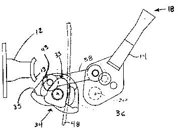
FIG.3 is schematic view of several elements of the
latch assembly;
FIG.4 is schematic view of several elements of the
latch assembly; and,
FIG.5 is schematic view of several elements of the
latch assembly.
Mode ~or Carrying Out the Invention
FIG.1 shows a perspective view of the latch assembly
10 and the complimentary keeper 12. In a typical
application, the keeper 12 will be mounted on a window
structure by the placement of mounting screws through -
mounting aperture 26 and mounting aperture 28. The
latch assembly 10 will be mounted on a casement or
window sill through the use of mounting aperture 22 and

21147~1
mounting aperture 24. In use, the window is hinged so
that the keeper 12 can move along a closure path 30
toward the latch assembly 10 as the window is closed.
When the keeper 12 is adjacent the latch assembly
10, the latch handle 14 can be rotated about axis 20
into a ~locked~ position 15 shown in phantom outline in
FIG.l, from the ~open~ position 18 shown in phantom
outline in FIG.l. In a similar fashion, movement of the
handle 14 from the "lockedn position 15 to the "open" or
unlocked position 18 releases the keeper 12 and it is
free to exit the latch 10.
Movement of the handle 14 between the locked
position 15 and the unlocked position 18, causes the so
called ~bolt~' to rotate. The rotation o~ the bolt
causes the keeper 12 to be lifted in the vertical
direction indicated by the path arrow 32 and to be
pulled into the latch housing as indicated by the
closure path arrow 30. This movement of the bolt closes
the window and supplies sufficient force to the window
to provide a good seal against weather stripping.
Both the latch assembly 10 and the keeper 12 are
symmetrical and they may be mounted for use with right
handed or left handed windows.
FIG.2 is an exploded view of the latch assembly 10. ~
25 This view shows an outer latch housing 11 and an inner -'
latch housing plate 21. The interior portion of the
handle 14 is visible in the figure. This portion of the
handle 14 is mounted for pivotal rotation around a
' ''' ~

. . ,., 1
handle axis 20. The bolt 34 is also shown and it is
mounted for pivotal rotation about a bolt axis 35.
First link 38 and second link 40 are shown as well and
these links connect the handle 14 to the bolt 34. First
¦ 5 link 38 has a journal 39, which mates with a
corresponding journal aperture 41, located in the handle ; ~ `
14. An upper link pin 42 is fitted in the first link
38, to communicate with an arcuate first link pin slot ~ ~
50, located in the bolt 34. In a similar fashion, the `
second link 40 carries a link pin 44, which mates with
an arcuate second link pin slot 52, formed in bolt 34.
The outer housing 11 carries a pair of spring retention
features one of which can be seen in FIG.2 and is
identified by reference numeral 51, a portion of the
leaf spring 48 is shown nested in the retention feature
51.
FIG.2, FIG.3 and FIG.4 should be considered
together. These figures show the handle 14 the bolt 34
and one of the links 38 in a variety of positions. For
clarity the housing and lower link are not shown in
these views.
FIG.3 corresponds to the handle 14 in the unlocked
position l9. In this view the bolt is fully rotated
into the open position to capture the keeper 12. ~he
bolt 34 includes a hook shaped bolt pulling surface 35
which is positioned beneath the keeper hook 13 in the
figure. In this position the spring 48 is in its
minimum energy state and it biases the bolt in the fully
~ ;~

211~76~ ~
~ ~
counterclockwise direction. As shown in the figure the
bolt includes a cam surface 33 which abuts the spring
48. in use the spring provides a force to maintain the
bolt in the fully rotated position. This permit
substantially more bolt rotation than would be possible
with the links alone and this contributes to the ability
of the latch to accommodate misaligned keepers.
FIG.4 shows the rotation of the handle 14 toward the
intermediate position 17. In this position the cam
10 surface 33 has deflected the spring in to it maximum ~ -
energy sate.
The handle 14 lever pulls on the first link 38 which in
turn causes the first link pin 42 to abut the end of the
first link pin slot 50 to rotate the bolt 34 into this
15 intermediate position. It is important to note that the .
bolt 34 includes a bolt lifting surface 37 which will
bottom out on the keeper hook 13 and the keeper 12 is
drawn into the latch housing 11. In FIG.3 this surface
37 lies somewhat below the bolt axis 36, while in FIG.4
the surface 37 lies above the bolt axis. Consequently
if the keeper hook 13 has sagged it will be lifted ;~
during bolt 34 rotation which typically facilitates
window closure.
FIG.5 shows the latch assembly in locked position
15. In this figure the keeper 12 is drawn into the
locked position 15 by bolt 34 rotation. The handle 14
is connected to the bolt through the first link 38. As -
! seen in the figure the centerline 31 of the first link
......

2~1~76~
38 is located below the handle axis 20 in this locked
position. By positioning the centerline 31 below the
handle axis 20 results in an over-center toggle action
and forces supplied to the bolt which tend to force the :
5 bolt 34 in the counterclockwise rotation move the handle :-
in the clockwise direction. This action causes the ;:~
latch assembly to latch firmly and to resist being pried
open.

Dessin représentatif
Une figure unique qui représente un dessin illustrant l'invention.
États administratifs

2024-08-01 : Dans le cadre de la transition vers les Brevets de nouvelle génération (BNG), la base de données sur les brevets canadiens (BDBC) contient désormais un Historique d'événement plus détaillé, qui reproduit le Journal des événements de notre nouvelle solution interne.

Veuillez noter que les événements débutant par « Inactive : » se réfèrent à des événements qui ne sont plus utilisés dans notre nouvelle solution interne.

Pour une meilleure compréhension de l'état de la demande ou brevet qui figure sur cette page, la rubrique Mise en garde , et les descriptions de Brevet , Historique d'événement , Taxes périodiques et Historique des paiements devraient être consultées.

Historique d'événement

Description Date
Inactive : CIB de MCD 2006-03-11
Demande non rétablie avant l'échéance 2000-02-02
Le délai pour l'annulation est expiré 2000-02-02
Réputée abandonnée - omission de répondre à un avis sur les taxes pour le maintien en état 1999-02-02
Demande publiée (accessible au public) 1994-08-03

Historique d'abandonnement

Date d'abandonnement Raison Date de rétablissement
1999-02-02

Taxes périodiques

Le dernier paiement a été reçu le 1998-01-15

Avis : Si le paiement en totalité n'a pas été reçu au plus tard à la date indiquée, une taxe supplémentaire peut être imposée, soit une des taxes suivantes :

  • taxe de rétablissement ;
  • taxe pour paiement en souffrance ; ou
  • taxe additionnelle pour le renversement d'une péremption réputée.

Les taxes sur les brevets sont ajustées au 1er janvier de chaque année. Les montants ci-dessus sont les montants actuels s'ils sont reçus au plus tard le 31 décembre de l'année en cours.
Veuillez vous référer à la page web des taxes sur les brevets de l'OPIC pour voir tous les montants actuels des taxes.

Historique des taxes

Type de taxes Anniversaire Échéance Date payée
TM (demande, 4e anniv.) - générale 04 1998-02-02 1998-01-15
Titulaires au dossier

Les titulaires actuels et antérieures au dossier sont affichés en ordre alphabétique.

Titulaires actuels au dossier
WRIGHT PRODUCTS CORP.
Titulaires antérieures au dossier
MICHAEL W. KONDRATUK
Les propriétaires antérieurs qui ne figurent pas dans la liste des « Propriétaires au dossier » apparaîtront dans d'autres documents au dossier.
Documents

Pour visionner les fichiers sélectionnés, entrer le code reCAPTCHA :


Pour visualiser une image, cliquer sur un lien dans la colonne description du document. Pour télécharger l'image (les images), cliquer l'une ou plusieurs cases à cocher dans la première colonne et ensuite cliquer sur le bouton "Télécharger sélection en format PDF (archive Zip)" ou le bouton "Télécharger sélection (en un fichier PDF fusionné)".

Liste des documents de brevet publiés et non publiés sur la BDBC .

Si vous avez des difficultés à accéder au contenu, veuillez communiquer avec le Centre de services à la clientèle au 1-866-997-1936, ou envoyer un courriel au Centre de service à la clientèle de l'OPIC.


Description du
Document 
Date
(aaaa-mm-jj) 
Nombre de pages   Taille de l'image (Ko) 
Abrégé 1994-08-02 1 73
Dessins 1994-08-02 5 409
Revendications 1994-08-02 1 82
Description 1994-08-02 6 522
Dessin représentatif 1998-08-24 1 8
Courtoisie - Lettre d'abandon (taxe de maintien en état) 1999-03-01 1 187
Taxes 1997-01-29 1 96
Taxes 1996-01-18 1 93