Note : Les descriptions sont présentées dans la langue officielle dans laquelle elles ont été soumises.
21i~
TRANSMISSION POWER TESTING BAR OF CABLE TELEVISION SYSTEM
FIELD OF THE lNvh~l-lON
The present invention relates generally to a test bar,
and more particularly to a test bar for use in combining the
main line distributors of a cable television system.
BACKGROUND OF THE l~VhN'l'lON
The television set of a cable television subscriber
receives the program signals directly from the coaxial
cable. With a view to cutting the cost of the coaxial cable
and allowing more subscribers to re-ceive the program signals
on the same coaxial cable, the cable television operator
makes use of a main line distributor on the primary line so
as to distribute the program signals to a plurality of the
secondary lines capable of reaching a number of cable
2il~81~
television subscribers. In addition, the cable television
operator must determine the extent of the loss of the
transmission power of the coaxial cable in the course of
transmission. Therefore, the main line distrib~tor is
provided additionally with a test hole for testing the
magnitude of the power signal in order to determine if a
power amplifier is called for. As shown in FIG. 1, a main
line distributor 10 capable of branching out one primary
line into three secondary lines is provided with a housing
11 having respectively at both front and rear ends thereof
two connecting heads 12 for use in connecting the secondary
lines of the subscribers with the primary line of the cable
television antenna line transmission system. The housing 11
is further provided respectively in both left and right
sides thereof with a test hole 14 having axially a test
point, which is not shown in the drawing, for use as a
reference in testing the magnitude of the power signal at
the time when the subscriber's antenna is receiving the
signal. The shortcomings inherent in the prior art power
testing are described explicitly hereinafter.
The main line distributor 10 is generally fastened to a
telephone pole or a rooftop. As a result, it is often
inconvenient as well as hazardous for a technician to climb
up to the main line distributor 10 to touch with a signal
gauge the test point of the test hole 14 of the main line
distributor 10. In addition, the test result- is often
211~813
._ .
inaccurate because the test is done hastily by the
technician who is more concerned about his or her own
safety.
The prior art power testing requires that the signal
gauge is caused to make a direct contact with the test point
of thé test hole 14 of the main line distributor 10. Such a
prior art testing method can often bring about an inaccurate
power testing value in view of the fact that the direct
contact between the signal gauge and the test point can
result in an antagonism of impedance between the signal
gauge and the coaxial cable.
SUMMARY (:IF THE lN Vl~;N'l'lON
The primary objective of the present invention is,
therefore, to provide a transmission power testing bar
intended for use in the cable television system and provided
therein with a line having attenuation value so as to
minimize the loss of the impedance matching at the time-when
the coaxial cable is contacted by-the signal gauge.
Another objective of the present invention is to
provide a transmission power testing bar having an
appropriate elasticity for use in the cable television
21i4~13
system. Such a transmission power testing bar can be caused
to make an intimate contact with the test point of the main
line distributor, thanks to the elasticity of the
transmission power testing bar.
The foregoing objectives of the present invention are
attained by the transmission power testing bar, which
comprises a test set member, an inner sleeve, an outer
sleeve, and a copper connection head. The test set member is
made of a metal material and provided in the axial hole
thereof with an attenuation line. The test set member is
coupled at one end thereof with one end of a nonconductive
connection rod which has another end provided with a test
point in communication with the attenuation line. The test
set member is coupled at another end thereof with a
nonconductive engaging tube having axially a round hole
communicating with the attenuation line. The inner sleeve of
a metal material has circumferentially a first portion and a
second portion. In addition, the inner sleeve has axially a
through hole dimensioned to receive therein the test set
member. The through hole has one end that is threaded and
another end that is flat. The first stepped portion is
provided with a spring. The outer sleeve of a metal material
has circumferentially an outer threaded portion and has an
axial hole. The copper connection hèad is provided axiaIly
with a through hole having at the front end thereof a
protruded portion and having circumferentially a stepped
-~ 211481~
ring forming an outer threaded portion. The outer threaded
portion of the outer sleeve is coupled with the test hole of
a main line distributor. With the help of the elastic force
of the spring, the test point of the test set member is
caused to urge tightly the center point of the test hole of
the main line distributor so as to ensure that the signal
gauge fastened to the copper connection head is enabled to
measure accurately the power testing value.
BRIEF DESCRIPTION OF THE DRAWINGS
FIG. 1 shows a perspective view of a main line
distributor of the prior art.
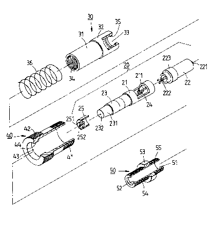
FIG. 2 shows an exploded view-of the present invention.
FIG. 3 shows a perspective view of the present
invention in combination as shown in FIG. 2.
FIG. 4 shows a sectional view of a test bar of the
present invention before being joined with a main line
distributor.
- 2114813
FIG. 5 shows a sectional view of the test bar of the
present invention after being joined with the main line
distributor.
DETATT~F.n DESCRIPTION OF THE lNv~NllON
Referring to FIGS. 2-4, a cable television transmission
power testing bar 2 embodied in the present invention is
fastened to the test hole of a conventional main line
distributor and is composed of a test set member 20, an
inner sleeve 30, an outer sleeve 40 and a copper connection
head 50.
The test set member 20 comprises a test rod 21, a
connection rod 22, and an engaging tube 23. The test rod 21
of a metal material has an axial hole 211 rècelving therein
an attenuation line 24. The connection rod 22 of a plastic
material has one end that is coupled with the test rod 21
and another end that is provided with a test point 221
communicating with the attenuation line 24 of the test rod
21 by means of a copper wire 222 located in the axis of the
test point 221. The connection rod 22 is provided
circumferentially with a stepped portion 223. The engaging
tube 23 of a plastic material has one end that is connected
with the test rod 21 and another end that is provided with a
211~13
_
tapered portion 231 which is fitted over with a tightening
casing ~5 of a rubber material. The tightening casing 25 is
provided at the anterior end thereof with a round projection
251 and is further provided axially with a round hole in
communication with a round hole 232 of the engaging tube 23
for allowing a probe of the signal gauge (not shown in the
drawings) to be inserted thereinto to communicate with the
attenuation line 24 of the test rod 21.
The inner sleeve 30 of a metal material has a first
portion 31, a second portion 32, and a thraugh hole 33
located axially for receiving therein the test set member
20. The through hole 33 has one end that is adjacent to the
first portion 31 and is provided with an inner threaded
portion 34. The through hole 33 has another end that is
provided with a protruded ring 35 to be urged by the stepped
portion 223 of the connection rod 22 of the test set member
20. The first portion 31 is fitted into a spring 36 having
one end which urges a junction between the first portion 31
and the second portion 32.
The outer sleeve 40 of a metal material is provided
circumferentially at one end thereof with an embossed
portion 41 and at another end thereof with an outer threaded
portion 42. The outer sleeve 40 is further provided axially
with a fitting hole 43 dimensioned to fit over the second
portio-n 32 of the inner sleeve 30 and the spring 36. The
~ 2114813
fitting hole 43 has one end that is adjacent to the embossed
portion 41 and provided annularly with a flat portion 44 to
be urged by the spring 36 of the inner sleeve 30.
The copper connection head 50 is provided axially with
a through hole 51 dimensioned to receive therein the
engaging tube 23 and the tightening casing 25 of the test
set member 20. The through hole 51 is provided at the
anterior end thereof with a protruded portion 52 to be
pressed against by the round projection 251 of the
tightening casing 25. The copper connection head 50 is
provided at the midsection thereof with a protruded ring 53.
Located on both sides of the protruded ring 53 are two outer
threaded portions 54 and 55, with the threaded port-ion 54
being engageable with the inner threaded portion 34 of the
inner sleeve 30, and with the threaded portion 55 being
engageable with the test head of the signal gauge.
In combination, the test set member 20 is first
received in the through hole 33 of the inner sleeve 30 such
that the stepped portion 223 of the connection rod 22
presses against the protruded ring 35 o~ the inner sleeve
30, as shown in FIG. 4. The spring 36 is then fitted over
the first portion 31 of the inner sleeve 30 such that the
outer sleeve 40 is fitted over the spring 36 and the second
portion 32, and that the flat portion 44 of the outer sleeve
40 is urged by the spring 36. Finally, the outer theaded
- 21i481~
portion 52 of the copper connection head 50 is caused to
engage the inner threaded portion 34 so as to ensure that
the outer sleeve 40 is confined by the protruded ring 53 of
the copper connection head 50 and that the outer sleeve 40
does not become disengaged with the inner sleeve 30.
In using the testing bar 2 of the present invention,
the embossed portion 41 of the outer sleeve 40 is held with
fingers to cause the test point 221 of the connection rod 22
of the test set member 20 to make contact with the center
point 82 of the test hole 81 of the main line distributor
80, as shown in FIG. 4, so as to cause the spring 36 to
compress. Thereafter, the outer threaded portion 42 of the
outer sleeve 40 is caused to engage securely the inner
threaded portion 83 of the test hole 81, thereby causing the
testing bar 2 to be fastened securely with the main line
distributor 80, as shown in FIG. 5. It is then ready for the
technician to insert the probe of the signal gauge into the
round hole 252 of the tightening casing 25. The power
transmission value of the coaxial cable is then measured via
the attenuation line 24 of the test set member 20. The power
transmission value of the coaxial cable can be so meas~red
accurately by virtue of the fact that the attenuation line
24 makes it possible to reduce the power loss at the time
when the testing bar Z is matched with the impedance of the
main line distributor 80.
1 3
-
The test point 221 of the connection rod ~ of the
testing bar 2 of the present invention can be caused to make
an intimate contact with the center point 82 of the main
line distributor 80, thanks to the elastic force of the
spring 36 of the inner sleeve 30.
The embodiment of the present invention described above
is to be regarded in all respects as merely illustrative and
not restrictive. Accordingly, the present invention may be
embodied in other specific forms without deviating from the
spirit thereof. The present invention is therefore to be
limited only by the scope of the following appended claims.