Sélection de la langue

Search

Sommaire du brevet 2115846 

Énoncé de désistement de responsabilité concernant l'information provenant de tiers

Une partie des informations de ce site Web a été fournie par des sources externes. Le gouvernement du Canada n'assume aucune responsabilité concernant la précision, l'actualité ou la fiabilité des informations fournies par les sources externes. Les utilisateurs qui désirent employer cette information devraient consulter directement la source des informations. Le contenu fourni par les sources externes n'est pas assujetti aux exigences sur les langues officielles, la protection des renseignements personnels et l'accessibilité.

Disponibilité de l'Abrégé et des Revendications

L'apparition de différences dans le texte et l'image des Revendications et de l'Abrégé dépend du moment auquel le document est publié. Les textes des Revendications et de l'Abrégé sont affichés :

  • lorsque la demande peut être examinée par le public;
  • lorsque le brevet est émis (délivrance).
(12) Demande de brevet: (11) CA 2115846
(54) Titre français: PINCE D'ABATTAGE POUR UNE ABATTEUSE D'ARBRES POLYVALENTE
(54) Titre anglais: FELLING GRAPPLE FOR A MULTI-FUNCTION TREE HARVESTER
Statut: Réputée abandonnée et au-delà du délai pour le rétablissement - en attente de la réponse à l’avis de communication rejetée
Données bibliographiques
Abrégés

Abrégé anglais


ABSTRACT OF THE DISCLOSURE
A felling, delimbing and cutting grapple for a multi-
function tree harvester. The grapple frame consists of two
support arms joined by a pin, the angle between the support
arms being set by a hydraulic actuator. One of the support
arms carries an upper delimbing cutter rigidly mounted to the
arm, while the other arm carries an upper delimbing cutter on
a hinge mounting, this delimbing cutter being guided by the
upper delimbing cutter. The lower delimbing cutters are
separately mounted on the support arms and by means of the
hinge pins and they are driven by the hydraulic actuators and
their postitions may be set through the hydraulic actuators
or through suitable machine elements, thus permitting the
cutters to be set at a distance from the trunk held in the
feed rollers during a delimbing operation.

Revendications

Note : Les revendications sont présentées dans la langue officielle dans laquelle elles ont été soumises.


WO 93/03604 PCT/FI92/00227
CLAIMS
A felling, delimbing and cutting grapple for a multi-function
tree harvester, characterised in that:
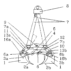
- an upper delimbing cutter 3a (Illustration 1) is fixedly
mounted to a scissors-like support arm 11 and another upper
delimbing cutter 3b is mounted through a hinge 6b to a support
arm 10, the hinged delimbing cutter 3b being guided from the
upper delimbing cutter 3a by means of piece 4
- support rollers 5 and 6 have been built on the upper
delimbing cutters 3a and 3b to prevent the cutters from cutting
and gripping the trunk of a tree during a delimbing operation
- one roller acts as length measurement device using a known
method
- feed rollers 1 or alternatively drive wheels are mounted on
the support arms 10 and 11, which are joined through the hinge
9 such that the force exerted by the hydraulic actuator 12 to
bring together the support arms causes the feed rollers 1 to
compress the tree being processed, whereby a measurement by
means of the sensor 15 (Illustration 3) of the angle defined
by the support arms will produce a determination of the
diameter of the tree
- the lower delimbing cutters 2a and 2b, separately hinged to
the support arms 10 and 11 through the pins 6a and 6b,
controlled through the hydraulic actuators 13a, 13b, 13c and
13d, set in position through the hydraulic actuators 16a, 16b,
16c and 16d or through other suitable machine elements, can be
held at a distance from the trunk being fed by means of the
feed rollers 1 to the delimbing process
- several tree trunks may be guided by means of the lower

WO 93/03604 PCT/FI92/00227
delimbing cutters between the feed rollers and pressed therein
in order to allow processing of several trees in a single
operation.

Description

Note : Les descriptions sont présentées dans la langue officielle dans laquelle elles ont été soumises.

~ ` W093/a3604 PCT/~9~/00227
8 ~ ~
Felling grapple for a multi-function tree harvester
The operation of the delimbing cutters of current felling,
delimbing and cutting grapples have prese~ted many
S dif~iculties. The compressive ~orce applied to the cutters has
usually varied directly with the magnitude of khe load. Thus
the high driving power required at the feed rollers to process
r large branches increases the pres~ure o~ the delimbing cutters
against the trunk of the tree, creating a ten~ency for the
10 delimbing cut~ers to choke. If the ad3ustment of the delimbing
cutters is made independent o~ the pressure regula~ion of the
feed rollers, the delimbing cutters then constantly demand an
active control during operativn of the harve~ter. Both
conditions make it dif~icult to achieve a ~lexible proce~sing
15 of a tree. At the same time, the power demands of the feller
grapple increases tremendously~ which in turn necessitates ~ore
power and weight at the hydraulic mo~ors of the ~rapple and
more strength and weight at the grapple.
20 Due to its location at the end of a long hydraulically
articulated boom, the weight of a feller grapple forms one of
! ' ' the determinant factors ~or the operativity of a multi-function
tree harvester.
:, . ';
: - 25 Forest thinning requires a high operating speed from a tree :~
ha~vester with respect to each felled tree. Thus the capability
to process more than one tree at the same time becomes an
importan~ factor.
~(~13S~ 117'F ~ E~ : .

W093/~36~ PCT/~192/00227
2 ~ &
The characteristics of thè invention are described in the
claims.
Illustrations l, 2 and 3 depict one application of this
5 invention so that the working parts are drawn with full lines
and the struc~ural par~s with broken lines~ In Illustration 1,
the feller grapple is represented p~rpendicular to the
direction of travel o~ the tree, in Illus~ra~ion 2 the feller
. grapple is shown in side view with the direction of travel of
10 the tree parallel to t~e illustration plane, while in ~~
Illustration 3 the grapple is æhown in top view above the
direction of tra~el of the tree.
Illustration 1 shows the rubberised feed rollers at the sides
lS of the grapple, which are used to move the trunk. They are
provided with a suitable fric~ion surface and are driven by
hydraul-ic power. The f~ed rollers 1 are mounted to supporting
arms lO and 11, which open and close around a hinge pin 9 by
means of a double-acting hydraulic actuator l~ mounted on hinge
20 pins 7a and 7b. (
The support arms 10 and 11 also carry the lower delimbing
cutters 2a and 2b, which are mounted on the arms through the
bearing hinges 6a and 6b and which are controlled by the
double-acting hydraulic actuators 13a and 13b. The fully closed
S position of the lower delimbing cutt2rs 2a and 2b (as well as
the of the cutters 2c and 2d hidden by this projection) is set
by the hydraulic actu~tors 16a and 16b. These actuatsrs prevent
the lower delimbing cutters from choking on the trunk during
the delimbing process. The upper delim~ing cutter 3a forms part
SUBSTITOTE SHIET

W093J03604 PCT/Fl92~Q0227
2~5~
of t~e support arm ll, an~ it is paired with the upper
delimbing cutter 3b, rotating on the bearing hinge 6b and
guided by means of part 4. The upper delimbing cutters 3a and
3b are suitably sharpened a~ their leading edges, and the upper
5 deli~binq cutter 3a is provided wi~h a support roller 5 to
prevent choking, while the upper delimbing cutter 3~ is fitted
with a combined support and length measuring roller 6. The
feller grapple is ~upported by a tilting yoke 7 and a rotating
support 8 at the end of the harvester boom.
Illustration 2 provides a lateral view of the feller grapple~
The tilting yoke 7 is ~oined by part 14a to the feller grapple
body 10 through the pin 7a. The joining part 14a includes a
double-acting hydraulic actuator 12a which rotates the feller
15 grapple from a delimbi~g and cutting position to a felling
position and ~ack. The hydraulically powered cutting saw is
located in a protective casing 15. The cutting saw may be
operated manually by the harvester driver or semi-automatically
as programmed through the length measuring roller (Illustration
20 1, part 6) and the thickness measurement sensor (Illustration
3, part 15). The double-acting hydraulic actuator 13a drives
the lower delimbing cutter 2a and the double-acting hydraulic
actuator 13c the lower delimbing cutter 2c.
25 Illustration 3 gives a top view of the feller grapple with the
tilting yoke 7 removed. The thickness of the ~run~ is
determined by the sensor 15 ~easuring the angular variation
between the supporting arms 10 and 11 rota~ing about the hinge
pin 9.
8UBSTiT~TI~ SHI~ET

W093/03604 PCTtFl92/00227
4 ~ l~ 5
The design shown in Illustrations 1, 2 and 3 gives flexibility
to the feller grapple. It may be used both for heavy cuttings
as well as tAinning operations. The design has exceptionally
low energy requirements in delimhing. The rollers S and 6
S rotating on antifriction ~earings prevent the delimbing cutters
3a and 3b from cutting into the trunk during a delimbing
operation. The position a~ove the body of the tree being
delimbed of the lower delimbing cutters 2a, 2b, 2c and 2d, held
through pins 6a and 6b to the scissor~-like support arms lO and
10 11, is controlled from the feed rollers 1 ~y means of the
double~acting hydraulic ac~uators 13a, 13b, 13c and 13d and the
back s~op actuators 16a, 16b, l~c and 16d. This design allows
the application of a strong driving pressure by the feed
rollers 1 on the tree being delimbed while simultaneously
15 preve~ting the delimbing cutters from gripping the trunk by
keeping them suitably distant from the trunk surface during ~he
delimbing operation. Furthermore it lets the lower delimbing
cutters strongly grip the trunk during the felling of large
trees and under other ~pecial circumstances, only to let the
20 prescure be released and transferred to the feed rollers 1
during the delimbing operation. This grapple design also
simplifies cutting operations in that, when cutting trees of
~imilar dimensions, the gripping operation need be regulated
only through the actuator-12. Since the lower delimbing cutters
25 are flexibly mounted on bearings on the support arms 10 and 11
and are provided with ~eparate controls, they enable the
grapple to process simultaneously several small trees~ This may
be achieved by keeping a felled tree in the grapple by means
of the feed rollers 1 as the grapple remains in a vertical
$UB3STITUl~E SHE~

W093/036~ PCT/Fl92/OOZ27
2 ~
position, while gripping ~he next tree with the lower deli~bing
cutters during the cutting operation, a~ter which the lower
delimbing cutters force the tree into the grasp of the feed
rollers 1, and so on. ~fterwards the clus~er of trees can be
5 delimbed as a whole. The possibility also exists to gather
felled trees into ~he grapple using the same principle and then
to delimb several trees at once. This method of operation
presents important advantages, since the multi-~unction tree
harvester is spared several work stages, while thinning cuts
( 10 can be exploited more efficiently and costs are lowered.
The measurement of thickness in ~his design is carried out by
measuring the angle defined by the support arms 10 and ~1, the
di~tance between the ~eed rollers b~ing obtained through
15 calibration. Since the delimhing cutters, supported by the feed
rollers, are k~pt distant from the tree, the measurement
becomes much more accura~e than through a measurement by means
of the delimbing cutters. The result is a more reliable
thickness value.
The compressive force developed on the feed rollers 1 held
through the support arms lO and 11 remains a separate entity,
a~fecting solely the feed rollers l. In distinction from
conventional designs, the delim~ing stresses as well as the
25 acceleration and deceleration stresses are transmitted across
the hinges 6a and 6b to the support arms 10 and 11 at a
location close to the feed rollers 1. Thus the torque created
by these forces acts across a much shorter leverage arm and the
support arms 10 and 11, as well as the grapple as a whole, may
SIIBSTITIUTE SHE~

W093/0360~ PCT/FI92/002~7
6 ~ a 5
be conceived to a much light~r design.
Since the grapple in i~s entirety is located at the end of a
long ~oom, even small reductions in total mass can be employed
5 to maximise ef~iciency, either by reducing the total weight of
the multi-function tree harvester or by increasing the reach
of existing machines.
This desi~n offers ~ur~her advantages over conventional designs
10 in ~hinning cuts and un~er circums~ances where small trees are
processed. Through this invention, trees either previously
felled or ~roken by stor~s may be easily picked by bringing the
~upport arms 10 and 11 close ~ogether and opening the lower
deli~bing cutters to a suitable compressing position, where~y
15 gripping will succeed even on difficult terrain.
This invention may be bui~t in several ways using ~nown
components~ The feed rollers may be replaced by dri~i~g wheels,
the material may be high-strength steel in either sheet or
20 other form. Several components could be justifiably built of (
high-strength al~minium or rom some other known material. The
grapple uses known technology to provide motion and perform l~
measurements and it is mounted in a known ~ashion to the multi-
function tree harvester.
',
8U~3~t~TlJTE S~EET

Dessin représentatif
Une figure unique qui représente un dessin illustrant l'invention.
États administratifs

2024-08-01 : Dans le cadre de la transition vers les Brevets de nouvelle génération (BNG), la base de données sur les brevets canadiens (BDBC) contient désormais un Historique d'événement plus détaillé, qui reproduit le Journal des événements de notre nouvelle solution interne.

Veuillez noter que les événements débutant par « Inactive : » se réfèrent à des événements qui ne sont plus utilisés dans notre nouvelle solution interne.

Pour une meilleure compréhension de l'état de la demande ou brevet qui figure sur cette page, la rubrique Mise en garde , et les descriptions de Brevet , Historique d'événement , Taxes périodiques et Historique des paiements devraient être consultées.

Historique d'événement

Description Date
Demande non rétablie avant l'échéance 2003-08-12
Le délai pour l'annulation est expiré 2003-08-12
Réputée abandonnée - omission de répondre à un avis sur les taxes pour le maintien en état 2002-08-12
Inactive : Abandon. - Aucune rép dem par.30(2) Règles 2002-07-16
Inactive : Dem. de l'examinateur par.30(2) Règles 2002-01-16
Modification reçue - modification volontaire 1999-11-03
Lettre envoyée 1999-07-16
Inactive : Renseign. sur l'état - Complets dès date d'ent. journ. 1999-07-16
Inactive : Dem. traitée sur TS dès date d'ent. journal 1999-07-16
Exigences pour une requête d'examen - jugée conforme 1999-07-08
Toutes les exigences pour l'examen - jugée conforme 1999-07-08
Demande publiée (accessible au public) 1993-03-04

Historique d'abandonnement

Date d'abandonnement Raison Date de rétablissement
2002-08-12

Taxes périodiques

Le dernier paiement a été reçu le 2001-07-27

Avis : Si le paiement en totalité n'a pas été reçu au plus tard à la date indiquée, une taxe supplémentaire peut être imposée, soit une des taxes suivantes :

  • taxe de rétablissement ;
  • taxe pour paiement en souffrance ; ou
  • taxe additionnelle pour le renversement d'une péremption réputée.

Veuillez vous référer à la page web des taxes sur les brevets de l'OPIC pour voir tous les montants actuels des taxes.

Historique des taxes

Type de taxes Anniversaire Échéance Date payée
TM (demande, 5e anniv.) - petite 05 1997-08-12 1997-07-28
TM (demande, 6e anniv.) - petite 06 1998-08-12 1998-07-23
Requête d'examen - petite 1999-07-08
TM (demande, 7e anniv.) - petite 07 1999-08-12 1999-08-06
TM (demande, 8e anniv.) - petite 08 2000-08-14 2000-08-11
TM (demande, 9e anniv.) - petite 09 2001-08-13 2001-07-27
Titulaires au dossier

Les titulaires actuels et antérieures au dossier sont affichés en ordre alphabétique.

Titulaires actuels au dossier
JOUKO MOISIO
JUHA MOISIO
JUHA MOISIO
Titulaires antérieures au dossier
S.O.
Les propriétaires antérieurs qui ne figurent pas dans la liste des « Propriétaires au dossier » apparaîtront dans d'autres documents au dossier.
Documents

Pour visionner les fichiers sélectionnés, entrer le code reCAPTCHA :


Pour visualiser une image, cliquer sur un lien dans la colonne description du document. Pour télécharger l'image (les images), cliquer l'une ou plusieurs cases à cocher dans la première colonne et ensuite cliquer sur le bouton "Télécharger sélection en format PDF (archive Zip)" ou le bouton "Télécharger sélection (en un fichier PDF fusionné)".

Liste des documents de brevet publiés et non publiés sur la BDBC .

Si vous avez des difficultés à accéder au contenu, veuillez communiquer avec le Centre de services à la clientèle au 1-866-997-1936, ou envoyer un courriel au Centre de service à la clientèle de l'OPIC.


Description du
Document 
Date
(aaaa-mm-jj) 
Nombre de pages   Taille de l'image (Ko) 
Dessin représentatif 1999-05-12 1 12
Dessin représentatif 2002-01-04 1 12
Page couverture 1995-05-13 1 80
Dessins 1995-05-13 3 150
Abrégé 1995-05-13 1 55
Revendications 1995-05-13 2 107
Description 1995-05-13 6 413
Rappel - requête d'examen 1999-04-13 1 117
Accusé de réception de la requête d'examen 1999-07-16 1 179
Courtoisie - Lettre d'abandon (taxe de maintien en état) 2002-09-09 1 182
Courtoisie - Lettre d'abandon (R30(2)) 2002-09-24 1 170
PCT 1994-02-16 22 746
Correspondance 2002-02-07 1 19
Taxes 1996-07-08 1 56
Taxes 1995-06-24 1 57
Taxes 1994-07-12 1 129