Note : Les descriptions sont présentées dans la langue officielle dans laquelle elles ont été soumises.
CA 02115869 1998-09-16
METHOD AND DEVICE FOR SUPPLYING PULP TO
A HEADBOX OF A PAPER MACHINE
The present invention relates to a method and
device for supplying pulp through a supply pipe to an
inlet header of a headbox of a paper machine, more
specifically, a movement compensator, which permits
tilting of the headbox without causing excessive
torsional tensions in the supply pipe.
The supply pipe connected to a headbox of a paper
machine is often provided with means that permit
rotation of the supply pipe so that the headbox of a
paper machine can be tilted as desired and discharge
pulp from a discharge opening therein. It is known in
the prior art to manufacture at least a portion of the
supply pipe from an elastic material which permits
rotation of the supply pipe while the opposite end of
the elastic construction remains stationary. A drawback
of this construction is the poor strength of the
material. During tilting of the headbox, the end
connected with the headbox moves along a relatively wide
path while the opposite end of the supply pipe remains
stationary. The material is subjected to a high
torsional strain, as a result of which the service life
of the pipe is reduced.
The present invention is directed towards the
provision of a new and improved connection between a
stationary pulp supply pipe and the headbox to prevent
the formation of torsional strains in the supply pipe
during tilting movements of the headbox.
The present invention further is directed towards
the provision of a connection between a stationary pulp
supply pipe and a headbox without producing significant
directional changes in the flow of the pulp from the
supply pipe to the headbox.
In one aspect of the present invention, there is
provided an arrangement of a headbox of a paper machine
and an apparatus for compensating for movements taking
place during tilting of the headbox and preventing
transfer of strains from a pulp supply pipe in the
CA 02115869 1998-09-16
headbox to a stationary pulp supply pipe, the apparatus
comprising: a first straight pipe having first and
second opposed ends and a straight central axis
extending from the first end to the second end; first
connecting flange means for rotatably coupling the first
end of the first pipe directly to the pulp supply pipe
in the headbox such that the straight central axis of
the first pipe is at an oblique angle with respect to a
central axis of the pulp supply pipe in the headbox, the
first connecting flange means enabling rotation of the
first pipe relative to the pulp supply pipe in the
headbox such that the second end of the first pipe is
moved to different positions relative to the first end
of the first pipe upon rotation of the first pipe
relative to the pulp supply pipe in the headbox; a
second straight pipe having first and second opposed
ends and a straight central axis extending from the
first end to the second end; second connecting flange
means for rotatably coupling the second end of the first
pipe directly to the first end or the second pipe such
that the straight central axis of the second pipe is at
an oblique angle with respect to the central axis of the
first pipe, the second connecting flange means enabling
rotation of the first pipe and the second pipe relative
to each other such that the second end of the second
pipe is moved to different positions relative to the
first end of the second pipe upon rotation of the first
pipe relative to the second pipe; and third connecting
flange means for rotatably coupling the second end of
the second pipe to a stationary pulp supply pipe, the
third connecting flange means enabling rotation of the
second pipe relative to the stationary supply pipe such
that the first end of the second pipe is moved to
different positions relative to the second and of the
second pipe upon rotation of the second pipe relative to
the stationary supply pipe.
In another aspect of the present invention, there
is provided an arrangement of a headbox of a paper
2
CA 02115869 1998-09-16
machine and an apparatus for compensating for movements
taking place during tilting of the headbox and
preventing transfer of strains from a pulp supply pipe
in the headbox to a stationary pulp supply pipe, the
apparatus comprising: a first pipe; a first connecting
flange for connecting the first pipe to the pulp supply
pipe in the headbox, the first connecting flange being
structured and arranged to permit rotation of the first
pipe and the pulp supply pipe in the headbox relative to
each other; a second pipe; a second connecting flange
for connecting the first pipe to the second pipe, the
second connecting flange being structured and arranged
to permit rotation of the first pipe and the second pipe
relative to each other; a third connecting flange for
connecting the second pipe to a stationary pulp supply
pipe, the third connecting flange being structured and
arranged to permit rotation of the second pipe and the
stationary supply pipe relative to each other; and at
least one of the first, second and third connecting
flanges comprising a joint collar having a first groove
therein, the first groove being shaped to receive end
portions of a pair of pipes connected by means of the at
least one of the first, second and third connecting
flanges, an end portion of a first one of the pair of
pipes comprising a second groove in a front face
thereof , an end portion of a second one of the pair of
pipes having a shoulder on a front face thereof, the
shoulder being receivable within the second groove.
In the present invention, a joint construction is
formed that permits a tilting movement of a headbox,
i.e., a movement compensator, in conjunction with the
supply pipe connected to the headbox. The joint
construction comprises a first pipe, which is linked to,
and placed in an oblique angle in relation to, the pulp
flow header in the headbox so that it permits rotation
of the header in relation to the first pipe and vice
versa. The first pipe of the movement compensator is
connected with a second pipe, which is installed at an
3
CA 02115869 1998-09-16
oblique angle in relation to the first pipe of the
movement compensator.
The first pipe of the compensator is linked by
means of a flange joint that permits its rotation in
relation to the feed pipe through which pulp is supplied
and, in a corresponding way, the first pipe is linked by
means of a similar flange joint that permits its
rotation in relation to the second pipe of the
compensator. The second pipe of the compensator is
linked by means of another flange joint so that it can
rotate in relation to the pulp supply pipe placed in a
stationary position.
When the headbox of the paper machine is pivoted
around its pivot shaft, the movement compensator in
accordance with the present invention permits the
pivoting movement. The movement compensator in
accordance with the invention, which is a sort of an
articulated crank mechanism, permits shifting of the
headbox both in the y-direction and in the z-direction.
Thus, pivoting movements of the headbox do not produce
strains in the stationary pulp supply pipe. Also, the
running of the flow of the pulp through the compensator
is smooth because the pipe arrangement in the
compensator does not have major directional changes in
the direction of running of the pulp flow. In a pre-
ferred embodiment, the difference in height between the
center line of the supply pipe and the end of the first
pipe of the compensator is about 30 mm and, in a
corresponding way, the distance between the end of the
first pipe and the central axis of the pulp feed pipe is
about 30 mm.
In the construction in accordance with the present
invention which is connected to the supply pipe of the
headbox of the paper machine, the movement compensator
comprises a first pipe, connected to the supply pipe by
means of a connecting flange that permits rotation, and
a second pipe connected to the first pipe by means of
another connecting flange that permits rotation. The
4
CA 02115869 1998-09-16
second pipe is further connected to the stationary
supply pipe by means of an additional connecting flange
that permits rotation.
In accordance with another aspect of the present
invention, there is provided a method for compensating
for movements taking place during tilting of a headbox
of a paper machine and preventing transfer of strains
from a pulp supply pipe in the headbox to a stationary
pulp supply pipe, comprising the steps of: connecting a
first end of a first straight pipe having first and
second opposed ends and a straight central axis
extending therebetween to the pulp supply pipe in the
headbox via a first connecting flange such that the
straight central axis of the first pipe is at an oblique
angle with respect to a central axis of the pulp supply
pipe in the headbox, the first connecting flange
enabling rotation of the first pipe and the pulp supply
pipe in the headbox relative to each other such that the
second end of the first pipe is moved to different
positions relative to the first end of the first pipe
upon rotation of the first pipe relative to the pulp
supply pipe in the headbox; connecting the second end of
the first pipe to a first end of a second straight pipe
having first and second opposed ends and a straight
central axis extending therebetween via a second
connecting flange such that the straight central axis of
the second pipe is at an oblique angle with respect to
the central axis of the first pipe, the second
connecting flange enabling rotation of the first pipe
and the second pipe relative to each other such that the
second end of the second pipe is moved to different
positions relative to the first end of the second pipe
upon rotation of the first pipe relative to the second
pipe; and connecting the second end of the second pipe
to the stationary pulp supply pipe via a third
connecting flange which permits rotation of the second
pipe and the stationary supply pipe relative to each
other such that the first end of the second pipe is
4a
CA 02115869 1998-09-16
moved to different positions relative to the second end
of the second pipe upon rotation of the second pipe
relative to the stationary supply pipe.
In the method in accordance with the invention, a
first pipe is connected to a pulp supply pipe in the
headbox via a first connecting flange which permits
rotation of the first pipe and the pulp supply pipe on
the headbox with respect to each other. The method also
includes connecting the first pipe to a second pipe via
a second connecting flange which permits rotation of the
first pipe and the second pipe with respect to each
other, and connecting the second pipe to a stationary
pulp supply pipe via a third connecting flange which
permits rotation of the second pipe and the stationary
supply pipe with respect to each other. The first pipe
may be arranged such that a central axis is of the first
pipe is at an oblique angle in relation to a central
axis of the supply pipe in the headbox. The second pipe
may be arranged such that a central axis of the second
pipe is at an oblique angle in relation to the central
axis of the first pipe. At least one and preferably all
of the connecting flanges are provided with a groove
shape to receive end portions of a pair of pipes
connected by the connecting flanges.
The following drawings are illustrative of
embodiments of the invention and are not meant to limit
the scope of the invention as encompassed by the claims.
In the drawings:
Figure 1 is a side view of the headbox of a ~a~er
machine;
Figure 2A shows a movement compensator in accor-
dance with the present invention installed in the supply
pipe connected with the pulp-flow header when viewed in
the direction K1 indicated in Fig. 1;
Figure 2B shows the movement compensator in accor-
dance with the present invention viewed in the direction
of the arrow ICz indicated in Fig. 2A;
Figure 2C is an axonometric illustration of the
4b
CA 02115869 1998-09-16
geometry of the movement compensator in accordance with
the present invention;
Figure 2D shows the geometry of the illustration of
Fig. 2C viewed in the direction of the arrow K3;
Figure 3 is a sectional view taken along the line
I-I in Fig. 2A;
Figure 4 is a side view, partially in section, of
the flange construction used in the present invention
viewed in the direction of the arrow KQ in Fig. 3;
Figure 5 is an enlarged illustration of the area A
in Fig. 4.
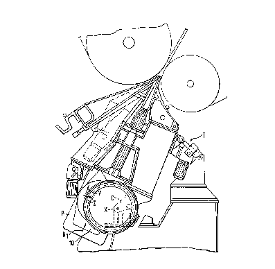
Referring to the drawings, Fig. 1 is a side view of
a headbox P of a paper machine. The headbox of the
paper machine is tilted by means of an actuator T. The
geometric pivot axis of the headbox of the paper machine
at bracket C is, in Fig. 1, denoted by the letter X.
The inlet header of the headbox P of the paper machine
is connected with a paper-pulp supply pipe S1. As an
articulation point that permits rotation of the pipe S1,
the supply pipe S1 comprises a connecting flange 10
which connects the supply pipe S1
4c
211869
to an intake pipe SZ.
Figs. 2A and 2B show a supply pipe S1, which is connected to
a headbox P of the paper machine and which is also connected to a
stationary pulp supply pipe SZ by means of a compensator
construction 10 in accordance with the present invention which
permits movement of the pipe S1. The geometric central axis of the
supply pipe S1 is denoted by X°. The central axis of the
stationary pulp supply pipe SZ is denoted with X°'. The movement
compensator 10 comprises a first pipe 11 linked to the supply pipe
S1 by means of an articulated connecting flange 12 that permits
rotation. The first pipe 11 is mounted so that its central axis X1
is placed at an oblique angle (a) in relation to the central axis
X' of the supply pipe S~. The connecting pipe 11 is connected to
the second pipe 13 by means of a connecting flange 14 which permits
rotation of the pipes 11,13. The second pipe 13 is arranged in a
direction which is inclined at an angle B in relation to the first
pipe 11 and to its central axis X1 and is connected to the
stationary pulp supply pipe SZ by means of a connecting flange 15
so that rotation of the pipes in relation to one another is
permitted. The central axis XZ of the second pipe 13 is aligned
with the central axis of the pulp supply pipe SZ as shown in Fig.
2A or may be positioned at an angle to the central axis of the pulp
supply pipe SZ as shown in Fig. 2B.
Fig. 2C illustrates the movement geometry of the compensator
in accordance with the invention. The movement compensator
comprises a pipe construction for connecting the supply pipe S1 to
the stationary pulp supply pipe S2. The compensator 10 comprises
a first pipe il and a second pipe 13. Between the first pipe 11
and the second pipe 13, there is a flange joint 14 that permits
rotation of the pipes in relation to one another. Between the
first pipe li and the supply pipe S1) there is a flange joint 12
that permits rotation of the pipes 11,S1 in relation to one
5
another, and between the second pipe 13 and the supply pipe S2,
there is a flange faint 15 that permits rotation of the pipes 13,52
in relation to one another. The common plane of the central axis
X' of the supply pipe S1 and of the central axis X, of the first
pipe 11 of the compensator 10 is denoted by T1. In Fig. 2C, the
plane that is perpendicular to the plane T1, and in which the
central axis X° of the supply pipe Si is placed, is denoted by T2.
In the construction in accordance with the invention) the second
pipe 13 of the compensator is placed in plane T3, which is parallel
to the plane T2. By means of this arrangement, tilting of the
headbox during operation and, thus shifting of the supply pipe S1
both in the direction Y and in the direction Z (in Fig. 1) are
permitted without causing substantial torsional strains in the
pipes.
Fig. 2D shows the arrangement of pipe equipment viewed in the
direction of the arrow K3 in Fig. 2C. End paints B1, BZ and B3 are
shown of the central axes of the pipes S1, 11 and 13, respectively,
viewed in the direction K3. The distance L1 between end points B1
and BZ is about 30 mm, and the distance LZ between end points BZ and
B3 is also about 30 mm. This preferred arrangement prevents
substantial directional changes in the pulp flow path from the
stationary pulp supply pipe SZ to the supply pipe Sl of the headbox.
When the compensator is placed in its position in connection
with the supply pipe S1 and SZ, the pipe 11 is preferably placed so
that the plane T1 intersects the pivot axis X3 about which the
headbox P is tilted. In such a case, both the central axis X' of
the supply pipe S1 and the central axis X" of the stationary supply
pipe SZ can be kept on the same line in the vertical plane and so
that there is just a small difference in height, e.g., about 30 mm,
between them.
Fig. 3 shows a sectional view of the connecting flange
construction used in the present invention taken along the line I-I
-6-
2~15~69
in Fig. 2A. The connecting flange construction 14 comprises a
joint collar 16 which may be opened. Flange 14 has two sides and
comprises collar halves 16a,16b linked to each other at an
articulation point 17. The collar halves 16a,16b of the joint
collar are joined together by means of a screw 18 which passes
through the brackets provided on the collar parts at an opposite
end of the flange 14 from the articulation point 17. ~ther
suitable connection means may also be used in the present
invention.
Fig. 4 shows the flange construction viewed in the direction
of arrow K4 in Fig. 3, i.e., as a side view partly in section.
Fig. 5 shows an enlarged illustration of area A of the joint
flange construction 14 shown in Fig. 4. The first pipe 11 of the
compensator is provided with an end portion G1 having a shoulder
and a flow opening. The second pipe 13 has an end portion GZ
provided with a shoulder and a flow opening. The side faces E1 and
EZ of the end portions G1,G2 with shoulders axe placed at an oblique
angle in relation to the radius R1 of the joint, in which case, by
turning the screw 18, it is possible to regulate the force with
which the pipes :L1,13 are pressed against one another. The
tightening force of the screw is determined so that rotation of the
first pipe 11 in relation to the second pipe 13 is permitted. The
side faces are jointly operative, by a wedge effect, with the side
faces U1 and UZ of the groove U in the collar. The joint collar 16
comprises a U-shaped groove section whose form corresponds to the
outer shape of the shoulders GI,Gz. When the joint collar 16 halves
16a,16b are joined together by means of the screw 18, the pipe
portions 11,13 to be joined together are pressed against one
another and kept together.
The pipe 11, which is provided with the end shoulder G1,
comprises a groove V in a front face N1 of the shoulder Gl. The
shoulder end GZ of the pipe portion 13 to be connected with end
_7_
211~s~~~
shoulder G1 can be placed into groove V so that the front~faae
shoulder D placed on the front face NZ of the shoulder end is
placed into the groove V.
Fig. 5 shows the area A in Fig. 4, i.e., the area in which the
connecting flange 14 is arranged between the pipes 11 and 13. A
construction similar to that described in relation to Fig. 5 is
also provided between the pipe 11 and the supply pipe Sl, i.e., the
connecting flange construction 12 is similar to the connecting
flange construction 14. In addition, between the pipe 13 and the
stationary supply pipe S2, there is a construction similar to that
between the pipe 11 and the pipe 13, i.e., the connecting flange
construction 15 is similar to the connecting flange constructions
14 and 12. Thus, only one of the connecting flange constructions
is illustrated by way of example, i.e., the connecting flange
construction 14 between the compensator pipes 11 and 13.
The examples provided above are not meant to be exclusive.
Many other variations of the present invention would be obvious to
those skilled in 'the art, and are contemplated to be within the
scope of the appended claims.
_g_