Note : Les descriptions sont présentées dans la langue officielle dans laquelle elles ont été soumises.
21 16754
~ACICGROUND OF THE INVENTION
The present invention relates generally to basters.
Basters to be used during cooking are well known.
The known baster includes a tube for taking gravy or the like,
and a rubber member compressible by a user so as to create a
suction and to suck gravy into the tube, for subsequent
~o discharge onto turkey, chicken and the like during cooking.
The disadvantage of the )cnown basters is that the gravy is
sucked all the way through the tube and into the rubber
memher, and after multiple use remains in the rubber member
and contaminate it. It is believed to be clear that such
contamination is not desirable. It requires thorough cleaning
of the baster, and in many cases the traces of the gravy in
the rubber member even after cleaning.
~lso, in the known basters when the gravy is taken
into the device and then held in its gravy holding receptacle,
the suction is usually not sufficient to hold the gravy inside
the device and the gravy drips from it.
-- 2
A 22386-~587
- - - 2 1 1 675~
1 Some devices of this general type are disclosed in
u.S. Patents 2,432,073, 2,887,035, 2,937,813, 2,991,945,
3,656,351, 3,836,057, 4,29,066. These devices can be further
improved.
s
21 1 6754
Accordingly, it is an object of the present
invention to provide a baster which eliminates the
disadvantages of the prior art and is a further improvement
S of the existing basters.
In keeping with these objects and with others which
will become apparent hereinafter, one feature of the present
invention resides, briefly stated, in a baster which has a
passage forming means for taking and accommodating of gravy
and the like and a suction forming means for creating a
suction in the passage, wherein the passage forming means
includes a cyLinder, and the suction forming means includes a
piston movable in the cylinder, and a handle connected with
the cylinder in two points spaced from one another in an axial
1~ direction of the cylinder so that an elongated a~ially
extending slot remains between the cylinder and the handle.
When the baster is designed in accordance with the
present invention, during the manufacture of the baster the
cylinder and the handle are not connected with one another
over a large area and therefore deformations of the cylinder
during the manufacture such as for example shrinkage are
avoided. This is of exceptional importance for the
manufacture of the baster, since the cylinder must be produced
with high accuracy in order to avoid untightness between the
piston movable in the cylinder and the inner surface of the
21 1 6754
1 cylinder. With even a slight untightness, the product to be
delivered can pass in a gap between the cylinder and the
piston.
In accordance with another advantageous feature of
s the present invention, a rear wall of the cylinder is providedwith passage means formed to prevent formation of a negative
pressure behind the piston during movement in a forward
stroke, which negative pressure renders resistance to the
advancement of the piston, wherein the passage means are
formed by a plurality of openings arranged circumferentially
around an axis of the cylinder at a radial distance from the
a~is. The passage means formed by the above specified
plurality of openings provide for optimal communication of the
space behind the piston with a surrounding atmosphere and
completely eliminate the negative pressure formation.
In accordance with still a further feature of the
present invention, the baster is provided with a long pipe
whlch guides the ~roduct to be delivered from the cylinder,
wherein the pipe is connected with the cylinder so that a rear
end of the pipe is tightly fitted on a forwardly e~tending
projection of the cylinder in a removable manner. This
substantially simplifies removal of the pipe for cleaning
purposes and its further mounting to the cylinder. Also,
seals can be arranged in grooves provided on the forward
2s projection of the cylinder so as to further improve the
2 1 1 6754
1 tightness between the rear end of the pipe and the ront
projection of the cylinder.
In accordance with still another advantageous
feature of the present invention, the rear end of the pipe has
S a diameter greater than the remaining portion of the pipe, so
that a shoulder is formed between the two portions of the pipe
against which the front face of the forward projection of the
cylinder abuts after mounting.
The piston can be composed of two plastic parts
connected with one another and forming wiping lips which
tightly abut against an inner surface of the cylinder,
to provide required tightness.
The novel features which are considered as
lo characteristic for the invention are set forth in particular
in the appended claims. The invention itself, however, both
as to its construction and its method of operation, together
with additional objects and advantages thereof, will be best
understood from the following description of specific
embodiments when read in connection with the accompanying
drawings.
2 1 1 6754
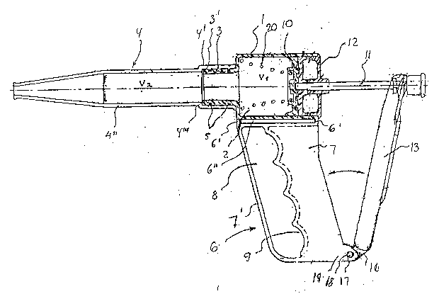
FIG. 1 is a side view of the baster in accordance
with the present invention;
FIG. 2 is a plan view of the baster in accordance
swith the present invention;
FIG. 3 is a view showing a rear end of a cylinder of
the inventive baster; and
FIG. 4 is an exploded view of several parts of the
inventive baster.
21 1 6754
,
The baster in accordance with the present invention
has a unit which forms a passage for taking and accommodating
gravy and the like. The passage forming unit includes a
cylinder which is identified with reference numeral 1 and
forms an inner chamber 2. A forward projection formed as a
sleeve 3 projects forwardly from the cylinder 1. An elongated
delivery pipe 4 is fitted on the sleeve 3 tightly, in a force-
transmitting manner for example by clamping of the pipe 4 on
the sleeve 3 with interposition of seals 5. The volu~e of the
cylinder 1 is equal to or greater than the volume of the pipe
.
Such a connection allows easy mounting of the pipe
4 on the sleeve 3 for operation of the baster, and dismounting
of the pipe from the sleeve for cleaning the baster.
As can be seen in the drawings, the pipe 4 has a
rear portion 4~ which is fitted on the sleeve 3, and a front
portion 4" extending forwardly from the rear portion. The
rear portion 4' has a greater diameter than the front portion,
so that a shoulder 4"' is formed between these portions. When
the pipe is fitted on the sleeve 3, the front end 3' of the
sleeve 3 abuts against the shoulder 4~ of the pipe 3.
The cylinder 1 is arranged on a handle 6 which in
the drawings extends downwardly of the cylinder. The handle
2s 6 is connected to the cylinder 1 only in two points 6" which
-- 8
`- 21 1 675~
1 are spaced from one another in an axial direction of the
cylinder. Therefore a longitudinal slot 6" is formed between
the cylinder and the handle. During the manufacture of the
baster, in which the cylinder and the handle are composed of
a plastic material, the cylinder 1 is not subjected to
deformations due to a substantially large-surface connection
with the handle as in k~own constructions, and therefore the
shrinkage of the cylinder does not occur and the cylinder is
produced with high accuracy, especially with respect to the
shape and size of its inner cylindrical opening in which a
piston is displaced as will be explained hereinbelow.
The handle 6 has a grasping part to be grasped by a
user~s hand, a front straight part 7', and a recess 8 provided
with a plurality of curved recessed portions 9. The recessed
portions 9 are formed to correspond anatomically to fingers of
the user, when the user inserts the fingers in the
opening ~ and grasps the portion 7.
The cylinder 1, the sleeve 3 and the handle 6 are
formed as a single one-piece element composed of thermoplastic
material. This substantially facilitates the manufacture of
the baster.
A unit is further provided with means for producing
suction in the cylinder 1 and the pipe ~. This unit includes
a piston 10 which is reciprocatingly movable in the chamber 2
2s of the cylinder 1 and has a piston rod 11. The piston 10 is
2 1 1 6754
1 formed as will be described below, so as to be sealed relative
to the cylinder 1. The piston rod 11 extends through a cover
12 which is removably connected with the cylinder 1, for
example by a thread or the like. ~ lever 13 has an upper
end which is connected with the rear end of the piston rod 11.
The connection can be performed, for example, by a slot. The
position of the upper end of the lever 13 on the piston rod 11
is locked by a nut 14 and a limiting knob 15. The lower end
of the lever 13 is pivotally connected with the handle 6. For
this purpose the lower end of the lever 13 has a forked
projection 16 provided with two pins 17 which pivotally engage
in holes 18 of a fork projection 19 provided on the lower rear
end of the handle 6.
During the operation the user holds the handle 8 and
presses the lever 13 toward the handle member 7. As a result,
the piston 10 is displaced forwardly to the front or left end
of the cylinder 1. A spring 20 is arranged inside the chamber
2 of the cylinder 1 and abuts with its one end against a
shoulder formed between the cylinder 1 and the sleeve 3 and
with its another end against the front surface of the piston
10 .
As can be seen from FIG. 3, the cover 12 which
closes the rear open end of the cylinder 1 has first passage
means which are formed as a central opening 21 for passing the
2s piston rod 11 therethrough and second passage means which are
-- 10 --
2 1 1 6754
1 formed by a plurality of openings 22. The openings 22 are
located on a common circumference around a central axis of the
piston and around the central opening 21 at the same radial
distance from the central axis. During the piston
displacement a negative pressure in the chamber located behind
the piston or in other words at the right side of the piston
in the drawings, is not formed since air is freely aspirated
through the openings 22 into this chamber. The front end of
the pipe 4 is introduced into a gravy receptacle. The user
releases the lever 13, and the lever under the action of the
spring 20 springs back and displaces the piston rod 11 with
the piston 10 rearwardly so as to produce suction in the
cylinder 1. Under the action of suction the gravy is
aspirated into the pipe 4, the sleeve 3 and the cylinder 1.
The baster is withdrawn from the gravy receptacle, and
thereafter the user again presses the lever 13 toward the
handle 6 to discharge the gravy onto turkey, chicken or other
product which is being cooked.
In order to clean the inventive baster, a cleaning
medium can be aspirated into the chamber 1 and discharged
several times. It is also possible to remove the pipe 4 from
the sleeve 3, the seals 5 from the sleeve 3, and the cover 12
from the cylinder 1, for cleaning. Thus, the cleaning of the
device is simple and efficient. The device also can be
cleaned so that no contamination residues remain in it. While
-- 11 --
- 2 1 i 675~
1 the gravy is sucked into the device it is reliably held under
the action of substantial suction force produced by the
device, and does not drip from the pipe 4.
As can be seen from ~IG. 4 the piston 10 has two
disc-shaped piston parts 10' and 10". The piston part 10' has
two annular grooves 21 and 22 of different diameters and a
central blind hole 23 in its right side in the drawing. At
the left side the piston part lO' has a central projection 24
in which the blind hole 23 is formed, a collar 25 having a
greater diameter and finally a peripheral collar 26 with a
narrowing lip 27. The piston part 10' is provided with two
annular projections 31 and 32 in its left side and a central
throughgoing opening 33. At the right side it has a
projection 34 in which a main part of the central opening 33
is formed, and a peripheral collar 35 with a narrowing lip 36.
The peripheral collars 27 and 35 have outer conical surfaces.
The piston parts 10' and 10" are composed of a synthetic
plastic material, for example of an elastomer. They are spin-
welded together with an E-ring 37 engaging in a groove 38 of
the shaft 1 and holding them in a position on the shaft. The
spring 20 is formed as a conical spring and its right end of
a smaller diameter fits over the collar 25 of the piston part
10~ in assembled condition. In this condition when the spring
20 is completely compressed, it is inserted in a depression 28
formed between the collar 25 and the collar 26 of the piston
- 12 -
2 1 1 675~
1 part 10' so that it does not take up any additional space
inside the cylinder. The collar 25 has an axial length which
is greater than the a~ial length of the collar 26 so that it
extends to the left axially beyond the collar 26. In turn,
the collar 34 has an axial length which is greater than the
axial length of the collar 35 and extends to the right axially
beyond the collar 35. Therefore in the end positions of the
piston the collars 34 and 25 act as shock absorbing members to
prevent damage to the lips 27 and 36 of the piston portions.
lo In the assembled condition the collars 26 and 35 are somewhat
radially compressed so as to tightly abut against the inner
surface of the cylinder and to prevent any untightness. At
the same time the lips 27 and 36 wipe the inner surface of the
cylinder during forward and rearward strokes.
The operation of the baster in accordance with the
present invention is simple, easy and efficient for its
intended purpose.
It will be understood that each of the elements
described above, or two or more together, may also find a
useful application in other types of constructions differing
from the types described above.
While the invention has been illustrated and
described as embodied in a baster, it is not intended to be
limited to the details shown, since various modifications and
structural changes may be made without departing in any way
- 13 -
`~ 2 1 1 6754
1 from the spirit of the present invention.
Without further analysis, the foregoing will so
fully reveal the gist of the present invention that others
can, by applying current knowledge, readily adapt it for
various applications without omitting features that, from the
standpoint of prior art, fairly constitute essential
characteristics of the generic or specific aspects of this
invention.
What is claimed as new and desired to be protected
~y Letters Patent is set forth in the appended claims.