Sélection de la langue

Search

Sommaire du brevet 2117564 

Énoncé de désistement de responsabilité concernant l'information provenant de tiers

Une partie des informations de ce site Web a été fournie par des sources externes. Le gouvernement du Canada n'assume aucune responsabilité concernant la précision, l'actualité ou la fiabilité des informations fournies par les sources externes. Les utilisateurs qui désirent employer cette information devraient consulter directement la source des informations. Le contenu fourni par les sources externes n'est pas assujetti aux exigences sur les langues officielles, la protection des renseignements personnels et l'accessibilité.

Disponibilité de l'Abrégé et des Revendications

L'apparition de différences dans le texte et l'image des Revendications et de l'Abrégé dépend du moment auquel le document est publié. Les textes des Revendications et de l'Abrégé sont affichés :

  • lorsque la demande peut être examinée par le public;
  • lorsque le brevet est émis (délivrance).
(12) Brevet: (11) CA 2117564
(54) Titre français: APPAREIL D'ECLAIRAGE MODULAIRE
(54) Titre anglais: MODULAR LIGHTING UNIT
Statut: Périmé et au-delà du délai pour l’annulation
Données bibliographiques
(51) Classification internationale des brevets (CIB):
  • F21V 21/00 (2006.01)
  • B60Q 1/00 (2006.01)
  • B60Q 1/04 (2006.01)
  • B60Q 1/26 (2006.01)
(72) Inventeurs :
  • KASBOSKE, GEORGE C. (Etats-Unis d'Amérique)
(73) Titulaires :
  • GEORGE C. KASBOSKE
(71) Demandeurs :
(74) Agent: FINLAYSON & SINGLEHURST
(74) Co-agent:
(45) Délivré: 1999-09-28
(22) Date de dépôt: 1994-08-24
(41) Mise à la disponibilité du public: 1995-05-03
Requête d'examen: 1994-10-27
Licence disponible: S.O.
Cédé au domaine public: S.O.
(25) Langue des documents déposés: Anglais

Traité de coopération en matière de brevets (PCT): Non

(30) Données de priorité de la demande:
Numéro de la demande Pays / territoire Date
08/145,819 (Etats-Unis d'Amérique) 1993-11-02

Abrégés

Abrégé anglais


A modular lighting unit with a case having a front and back and a peripheral
wall extending around a light chamber. A lens is mounted to the case. A reflector
in the light chamber directs light from a source forwardly through the lens. Theperipheral wall is defined at least partially by an exposed surface having a first
portion that is other than the flat surface extending either fully horizontally or fully
vertically. Structure is provided on the exposed surface portion for attaching another
modular lighting unit to the case.

Revendications

Note : Les revendications sont présentées dans la langue officielle dans laquelle elles ont été soumises.


10
The embodiments of the invention in which an exclusive
property of privilege is claimed are defined as follows:
1. A modular lighting unit comprising:
a case having a front and back and a peripheral wall extending around a light
chamber;
a lens;
means for mounting the lens to the case;
a reflector in said light chamber for directing light from a source forwardly
through said lens,
said peripheral wall being defined at least partially by an exposed surface
having a portion that is other than a flat surface extending either fully
horizontally or
fully vertically; and
means on the exposed surface portion for attaching another modular lighting
unit to the case.
2. The modular lighting unit according to claim 1 wherein the exposed
surface portion is flat.
3. The modular lighting unit according to claim 1 wherein the attaching
means comprises a plurality of ribs and recesses.
4. The modular lighting unit according to claim 1 in combination with a
mounting base, there further being means for removably connecting the case to
the
mounting base.
5. The modular lighting unit according to claim 4 in combination with a
guide rail to be attached to a support, there being means cooperating between
the
mounting base and guide rail to allow the mounting base to be maintained in a
plurality of different positions relative to the guide rail.

11
6. The modular lighting unit according to claim 5 in combination with a
support for the guide rail, said support comprising one of an on- and off-road
vehicle.
7. The modular lighting unit according to claim 4 wherein the mounting
base includes means for attaching the mounting base to a support and further
including levelling means for adjusting the attitude of the mounting base
relative to
a support for the mounting base.
8. The modular lighting unit according to claim 1 wherein the exposed
surface of the peripheral wall defines a diamond shape.
9. The modular lighting unit according to claim 1 in combination with a
second modular lighting unit that is substantially the same as the first
claimed
modular lighting unit, said second modular lighting unit having a second case
with
a second peripheral wall having a second surface portion that can be attached
to the
first surface portion through the attaching means.
10. The modular lighting unit according to claim 9 wherein the first and
second surface portions are each flat and angled so that with the first and
second
surface portions abutted to each other the first claimed and second modular
lighting
units have the same orientation.
11. The modular lighting unit according to claim 10 wherein the exposed
surfaces of the peripheral walls of the first claimed and second modular
lighting units
both define a diamond shape.
12. The modular lighting unit according to claim 1 in combination with
second and third modular lighting units that are each substantially the same
as the first
claimed modular lighting unit, the attaching means attaches the exposed
surface

12
portion of the first claimed modular lighting unit to the second modular
lighting unit,
there being a second means on the exposed surface portion of the first claimed
modular lighting unit for attaching the third modular lighting unit to the
first claimed
modular lighting unit.
13. The modular lighting unit according to claim 12 wherein at least one
of a) the means for attaching the exposed surface portion of the first claimed
modular
lighting unit to the second modular lighting unit and b) the second attaching
means
comprises a plurality of cooperating ribs and recesses.
14. The modular lighting unit according to claim 12 including means for
attaching only two of the three modular lighting units to a support therefor.
15. The modular lighting unit according to claim 1 in combination with a
second modular lighting unit and the attaching means comprises means for
attaching
the second modular lighting unit to the first claimed modular lighting unit so
that the
second modular lighting unit is supported in cantilever fashion from the first
claimed
modular lighting unit.
16. The modular lighting unit according to claim 1 wherein the attaching
means comprises means for removably attaching another modular lighting unit to
the
17. The modular lighting unit according to claim 12 in combination with
a fourth modular lighting unit that is substantially the same as the first
claimed
modular lighting unit, there are means on the fourth modular lighting unit for
attaching the fourth modular lighting to each of the second and third modular
lighting
unit.

13
18. The modular lighting unit according to claim 1 in combination with a
light source and means for mounting the light source to the case.
19. The modular lighting unit according to claim 1 wherein the reflector
has a diamond shape.
20. A modular lighting unit comprising:
a case having a front and back and a peripheral wall extending around a light
chamber;
a light source;
means for mounting the light source to the case,
said peripheral wall being defined at least partially by an exposed surface
having a portion that is other than a flat surface extending either fully
horizontally or
fully vertically; and
means on the exposed surface portion for attaching another modular lighting
unit to the case.
21. The modular lighting unit according to claim 20 wherein the exposed
surface portion is flat.
22. The modular lighting unit according to claim 20 wherein the attaching
means comprises a plurality of ribs and recesses.
23. The modular lighting unit according to claim 20 in combination with
a mounting base, there further being means for removably connecting the case
to the
mounting base.
24. The modular lighting unit according to claim 20 wherein the exposed
surface of the peripheral wall defines a diamond shape.

14
25. The modular lighting unit according to claim 20 in combination with
a second modular lighting unit that is substantially the same as the first
claimed
modular lighting unit, said second modular lighting unit having a second case
with
a second peripheral wall having a second surface portion that can be attached
to the
first surface portion through the attaching means.
26. The modular lighting unit according to claim 20 in combination with
a motorized vehicle, and means for attaching the modular lighting unit to the
vehicle
so that the modular lighting unit functions as one of a headlight, a turn
signal, a tail
light, a brake light, and a running light on the vehicle.

15
27. A lighting unit assembly comprising:
a plurality of modular lighting units including a first and a second modular
lighting unit each having:
a case having a front and back and a peripheral wall extending around a light
chamber;
a reflector in said light chamber for directing light from a source forwardly
from said case in a pattern centered on a fore-and-aft line;
first means for mounting at least one of the first and second lighting units
to
a mounting base in a first position such that with the at least one of the
first and second
lighting units in the first position the fore-and-aft line associated with the
at least one of
the first and second lighting units is horizontally oriented,
wherein the peripheral wall on the at least one of the first and second
lighting
units is defined at least partially by an exposed surface and with the at
least one of the first
and second lighting units in the first position the exposed surface thereof
has a portion that
is other than a flat surface extending either fully horizontally or fully
vertically; and
means on the exposed surface portion of the at least one of the first and
second lighting units and on the other of the first and second modular
lighting units for
attaching the first and the second modular lighting units to each other,
wherein there are second means on the exposed surface of the at least one of
the first and second modular lighting units for attaching a third one of the
plurality of
modular lighting units to the at least one of the first and second modular
lighting units,
there further being means other than the at least one of the first and second
modular
lighting units for attaching the third modular lighting unit to the other of
the first and
second modular lighting units.
28. The modular lighting unit according to claim 27 wherein at least one of a)
the
means for attaching the exposed surface portion of the first modular lighting
unit t the second

16
modular lighting unit and b) the second attaching means comprises a plurality
of cooperating
ribs and recesses.
29. The modular lighting unit according to claim 27 including means for
attaching
only two of the three modular lighting units to a support therefor.
30. The lighting unit assembly according to claim 27 including a fourth
modular
lighting unit and means on the fourth modular lighting unit for attaching the
fourth modular
lighting unit to at least two of the other modular lighting units.

Description

Note : Les descriptions sont présentées dans la langue officielle dans laquelle elles ont été soumises.


CA21 1 7564
MODUL~R LT-.~I~G UNIT
Ba~ of the Invention
Fi~ of the Invention
This invention relates to lighting equipment and, more ~ l~ly, to a
modular lighting unit that is y~Li~ul~ly suitable for use on on- and off-road vehicles
to serve as at least one of a headlight, turn signal, tail light, running light, brake
light, etc. on the vehicle.
- ~J ~ ~ ~ Art
It is know to place several different types of lights on on- and off-road
0 vehicles. On the top of truck cabs, running lights and spot lights are commonly seen.
This latter type of light is commonly mounted upon a bracket that spans laterally
across the top of the vehicle cab. A plurality of lights are mounted in spaced
, and project upwardly from the bracket. The individual lights, which may
be relatively heavy, are held in place principally by a depending stem that acts as a
pedestal. It is difficult with such a .~ - to maintain the lights in a stable
position and in proper alignment. With these lights on off-road vehicles, vibrations
and shock due to rough terrain often tend to work the lights loose from their
mounting. Even if the ]ights do not work loose, there is a tendency of the ]ights to
rattle as they flex about the pedestal-type mount.
Insomec~ . l; c if the]ightbecomes 'i" 1,itmustberemovedto
allow the mounting stem to be reshaped. The light must then be re ~

CA~l 1 7564
A fmther problem witn the above structure is that it is relatively limited with
respect to the number and ~ of lights on the bracket. Sufficient spacing
must be left between adjacent lights so that the lights do not contact each other as
when they flex with the vehicle in operation. At the same time, the lights must all
be mounted at the same vertical height, as dictated by the mounting bracket.
Still further, most of the brackets and mounting structures for the lights are
made from metal. C , 1~" as these patts rust or wrrode, it becomes more
difficult, and at times , ' ' to ' '- and adjust the lights.
Other lights mounted on vehicles, such as those used as headlights, running
lights, tail lights, turn signal lights, ruruung board lights, brake lights, etc., have the
same problems as discussed above.
Because of the constraints introduced by w..., ' mounting systems, the
cases for the above types of lights are usually made relatively simple in shape. That
is, in most instances, the cases are square or - _ ' . As a result, most of these
w,...... ' lights are usually, ~ ~, in terms of their arr
The inventor herein invented a system for mounting modular lighting units,
which invention is the subject of U.S. Patent No. 4,972,301.This invention
overcomes some of tne problems identified above.
Summary of the Invention
The ptesent invention is s~;r~ y directed to u.~the above-
' problems in a novel and simple manner.
In one form of the invention, a modular lighting unit is provided with a case
having a front and back and a peripheral wall extending around a light chamber. A
lens is mounted to the case. A reflector in the light chamber directs light from a
source forwardly through the lens. The peripheral wall is defined at least par~ally
by an exposed surface having a first portion that is other than a flat surface extending
either fully horizontally or fully vertically. Structure is provided on the exposed
sutface portion for attaching another modular lighting unit to the case.

C~ 2 i 1 7564
In one form, the e~posed surfwe is flat.
The attaching structure can take a number of different forms. In one form,
the attaching structure includes a plurality of ribs and recesses The lighting units can
be l '~ or removably attached.
The invention also , ' the ~ ~ of the above structure with
a mounting base to which the case can be connected.
The invention further; , ' the ' ~ of the above structure with
a guide rail to be attached to a support. The mounting base cooperates with the guide
rail to aUow the mounting base to be maintained in a plurality of different positions
relative to the guide rajl.
In one form, the support is one of an on- and off-road vehicle. The lighting
unit can function as one of a headlight, a turn signal, a tail light, a running lights, a
brake light, etc. on the vehicle.
To assist adjustment of the lighting unit, levelling structure can be provided
for adjusting the attitude of the mounting base relative to a support for the mounting
base.
The invention , ' the ~ A of a first modular lighting unit
with a second modular lighting unit, with the first and second modular lighting units
being ' ".~ the same. The second lighting unit has a second surface portion
that can be attached to the first surface portion on the first unit. In one form, the
first and second surface portions ate each flat and angled so that with the first and
second surface portions abutted to each other, the first and second lighting units have
the same ~
While the peripheral waU surface of the lighting units can ta~e a number of
different shapes, in one desirable form, the peripheral waU surface has a diamond
shape.
A third modular lighting unit, similar to the first and second lighting units, can
be provided. The first lighting unit can be rnnC~Irt~ to be attached to the third
lighting unit.

C~2i 1 7564 4
In one form, only two of the three modular lighting units are connected to a
support therefor, vith the other module being supported by the ! I '-~"'6-'6i"6
modules. The third module can be supported in cantilever fashion from one or both
of the other two modules.
A fourth lighting unit can be provided for connection to each of the second
and third modular lighting units.
With the inventive structure, a i ' amount of versatility is afforded.
The individual modules can be stac~ed and ' ' to provide a highly stable
system with an infinite number of different overall shapes and designs being possible.
A light source can be provided as part of the modular lighting unit.
In another form of the invention, a modular lighting unit is provided having
a case and a light source mounted to the case. The case has a peripheral waU defined
at least par~ally by an exposed surface having a first portion that is other than a flat
surface extending fully horizontally or fully vertically, with structure on the exposed
surface portion being provided for attaching another modular lighting unit to the case.
Detailed DP~~?~;'"' of the Drawines
Fig. 1 is a p~ . view of a modular lighting unit according to the present
invention assembled to a mounting base;
Fig. 2 is an exploded ~ . view of the modular lighting unit and
mounting base;
Fig. 3 is a ~ . view of the modular lighting unit on the mounting base
situated for . ~ with a guide rail to which the lighting unit can be attached
in a plurality of different positions;
Fig. 4 is a front elevation view of the modular lighting unit assembled to the
mounting base;
Fig. 5 is a side elevation view of the modular lighting unit;
Fig. 6 is a front elevation view of four modular lighting units assembled in
one ~ around a single mounting base;

CA 2 1 ~
Fig. 7 is a front elevation view showing nine modular lighting units coMected
together in another . fi_ on a plurality of mounting bases;
Fig. 8 is an enlarged, ' ~ ~, front elevation view of the COMectiOn
between two of the modular lighting units;
Fig. 9 is a ~ , view of one type of vehicle with modular lighting units
according to the present invention mounted thereon;
Fig. 10 is a view as in Fig. 9 with the modular lighting units mounted on the
vehicle in a different . 'i~ ;
Fig. 11 is a rear elevation view of a semi-truck/trailer with modular ]ighting
units thereon; and
Fig. 12 is an enlarged, ' _ y, front elevation view of a plurality of ribs
and recesses on joined modular lighting units.
~t~ DE~ 7~ n of the Drawin~
In Figs. 1-12, a modular lighting unit, according to the present invention, is
shown at 10. The lighting unit 10 has a case 12 with a peripheral waU 14 extending
around a light chamber 16 within which a light source 18 (Fig. 8) resides. Lightfrom the source 18 projects forwardly through a striped lens 20 at the forward portion
of tne case 12. A suitable ,~ for the lens 20 is described in my U.S. Patent
No. 4,586,116. However, it is not necessary that the lens 20 be other than clear or
i ' In fact, the lens 20 could be altogether eliminated.
Light projecting rearwardly from the light source 18 is redirected forwardly
by a reflector 22 at the rear of the case 12. The reflector 22 is likewise optional.
A mounting base 24 defines a cradle at 26 for the bottom 28 of the module 10.
The mounting base 24 provides a pedestaV' ~ for the module 10 upon a
support 30, as shown genericaUy at 30 in Fig. 7.
The case 12 has I , ".~, spaced, elongate ribs 30 extending in a fore and
aft direction, with there being recesses 32 defined between adjacent ribs 30. Each
rib 30 has oppositely facing side surfaces 34, 36 which diverge away from the case

CA2i 1 7564
12. The recesses 32 have a , ' y shape to accept a rib on a like module
10. The ribs 30 and recesses 32 are spaced;, ~ '~, so as to mesh with ribs 30
and recesses 32 on an adjoining, like module 10 in a plurality of different relative
positions.
S The wall 14 on each case 12 has four flat surface portions 38, 40, 42 and 44
which can be flushly abutted to any of the flat surfaces 38, 40, 42, 44 on a like
module 10 to be joined thereto. In one preferred form, the surfaces 38, 40, 42, 44
wu~ define a diamond shape.
While the peripheral wall 14 could have other shapes, it is desirable that at
least one of the flat surfaces 38, 40, 42, 44 extends other than $111y vertically or
horizontally to facilitate connection to another module 10. As seen most clearly in
Fig. 8, the angle ~ of the surface 42 on the lower module 10 is chosen to be equal
to the angle ~1 of the surface 40 on the ,; module 10 so that with the
modules 10 stacked as shown in Fig. 8, the two modules 10 have the same
i i.e with one upright, the other module attached thereto is upright. As a
result, the upper module 10 is held in cantilever fashion from the wall surface 42 on
the lower module 10 through the meshing ribs 30. Since the ribs 30 are spaced
, ' '.~, along the surfaces 40, 42, the two modules 10 can be connected in a
plurality of different positions along the line of the !' ~ ' I ' ' arrow 46.
The: v of the ribs 30 and recesses 32 is such that the modules 10
that are to be joined can be relatively positioned, one in front of the other, and moved
towards and against each other in a fore and aft direction to mesh the ribs 30. Once
the ribs 30 on adjacent modules 10 are in mesh, a screw or other type of wedge 48
(Fig. 12) can be directed into a bore 50 extending lengthwise into or through one of
the ribs 30 to lJlU~ ! effect a lateral expansion thereof, as imdicated by the
bowed side surface 34 shown in phantom lines in Fig. 12. This effectively locks
adjacent ribs 30 on the joined modules 10 to prevent 1r~ separation of the
joined modules 10.

CA 2 i 1 75 64 7
With the above described structure, the modules 10 can be rigidly meshed in
clusters in a variety of different attractive and functional shapes. In Fig. 6, four
modules, designated A, B, C and D, are shown assembled together to define a larger
diamond shape. The module A is carried on a mounting base 24 and connected to
modules B and D. The uppermost module C is coMected to both the modules B and
D. This structure affords a self-rigidifying _ by reason of the ~
of the modules A, B, C and D. Additional modules can be stacked upon the modulesB, C, D and each other to construct a further desired shape.
In Fig. 7, nine modules are shown, lettered E-M, arranged in a different
~ The lowermost modules E, F, G and H are each received in a
mounting base 24 which mounting bases 24 are f~xed to an underlying support 30.
The end modules M, I are each supported in cantilever fashion from a single module
E, H, ~ lJ. The other modules L, K, J are each connected to two modules.
This illt~l~ ' g: ~ permits a reinforced, sturdy assembly of modules 10
across a substantial width, as upon the cab 50 of a pickup truck 52, shown in Fig. 9.
The support 30 can be the vehicle 52 itself or a bracket which is attached to the
vehicle 52. In Fig. 9, the mounting bases 24 are attached directly to the vehicle 52.
A sim~ar a ~ of modules 10 is shown in front of the gri~ 54 on the
front of the vehicle 52 on the bumper 56. The modules 10 are stacked one layer
higher than the ~ shown in Fig. 7.
In Fig. 10, individual clusters of three are shown mounted upon the cab 50
and bumper 56 on the vehicle 52.
The joined modules 10 can be downsized and used as running lights, as on a
semi-truck/trailer, shown at 58 in Fig. 11. In Fig. 11, the single modules 10 are
shown to be used as brake and turn signal ]ights for the semi-ll.. ~L/I.~l,,. 58.
A further downsized version of the module 10 is shown at oO in Fig. 9 along
the edge of a running board 62 on the vehicle 52.
The modules 10 can be simply joined like building blocks to produce an
overall desired size and shape. The angular ~ of the surfaces 38, 40, 42,

~ A ~ J 6 4
44 facilitates stacking, provides a rigid ~t;l, ._lcd support between adjacent modules
10, provides a rigid coMectiOn between two joined modules, and allows unique
sha~es to be created at the point of use by a consumer.
Further, the consumer can ~ ' '~ and re-assemble the modules 10 in a
desired shape.
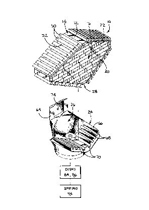
The ribbed _ of the case 12 also facilitates connection of the case
12 to the mounting base 24. The mounting base 24 is generally ~shaped with a
vertically extending wall 64 and a horizontally extending wall 66. The wall 66 has
ribs 68 and recesses 70 ~ ' ~ g to the ribs 30 and recesses 32 in terms of size
and spacing. The horizontal wall 66 has a V shape w.. c r ~ ~ to the bottom wall
of the case 12. The module 10 can thus be press fit from front to rear into operative
; _ _ with the mounting base 24. In that operative position, the rear wall 72
of the case resides in close proximity to the vertically extending wall 64 on the
mounting base 24.
The mounting base 24 has an undercut 74 to accept a mounting plate 76
having ribs 78 which can be slid vertically into mesh with ribs (not shown) on the
rear wall 72 of the case 12. A fastener, in the form of a screw 80, can be directed
through the wall 64, the plate 76 and into the case rear wall 82 to prevent separation
of the module 10 from the mounting base 24. D;~l.lbl~ of tbe module 10 from
the mounting base 24 can be ~ ' I by reversing the above steps.
A fura~er aspect of the invention is the provision of a levelling means at 82
by which the attitude of the combined module 10 and mounting base 24 can be altered
relative to the support 30 on which they are carried. A pair of sloped disks 84, 86
are placed in overlying l~' ' . In one relative position, the disks 84, 86
wu~cldi~ly define a uniform thickness. By relatively rotating the disks, as
indicated by the arrow 88, the thickened and thin portions of the disk 84, 86 reside
in different ' thereby causing the upper surface 90 of the disk 84, which
bears on the mounting base 24, to vary in attitude. A mounting bolt 92 can be

CA211 7564 9
directed through the disks 84, 86 and into tne mounting base 24 to fi~ the relative
positions thereof.
An optional spring 94 can be used to biasably capture the disks 84, 86 against
the mounting base 24 so that the relative positions of the disks 84, 86 and mounting
base 24 are frictionaUy maintained before the bolt 92 is tightened to positively fix this
1~ .
Another aspect of the invention is the provision of a mounting/guide rail 96
to accept a modified form of mounting base, as shown in Fig. 3 at 98. The mounting
base 98 has an enlarged disk 100 which fits in a slot 102 on the rail 96 to aUow the
disk 100, and module 10 associated therewith, to be slid along the rail 96. A bolt
104 can be directed through any of a number of bores 106 in the rail 96 to extend
into the mounting base 98 to fLlc the position of the mounting base 98 relative to the
rail 96 as desired.
The foregoing disclosure of specific e ~ is intended to be iUustrative
of the broad concepts ~ , ' ' ' by the invention.

Dessin représentatif
Une figure unique qui représente un dessin illustrant l'invention.
États administratifs

2024-08-01 : Dans le cadre de la transition vers les Brevets de nouvelle génération (BNG), la base de données sur les brevets canadiens (BDBC) contient désormais un Historique d'événement plus détaillé, qui reproduit le Journal des événements de notre nouvelle solution interne.

Veuillez noter que les événements débutant par « Inactive : » se réfèrent à des événements qui ne sont plus utilisés dans notre nouvelle solution interne.

Pour une meilleure compréhension de l'état de la demande ou brevet qui figure sur cette page, la rubrique Mise en garde , et les descriptions de Brevet , Historique d'événement , Taxes périodiques et Historique des paiements devraient être consultées.

Historique d'événement

Description Date
Inactive : CIB désactivée 2011-07-27
Le délai pour l'annulation est expiré 2007-08-24
Lettre envoyée 2006-08-24
Inactive : CIB de MCD 2006-03-11
Inactive : TME en retard traitée 2005-08-05
Lettre envoyée 2004-08-24
Inactive : TME en retard traitée 2002-08-23
Lettre envoyée 2001-08-24
Inactive : TME en retard traitée 1999-11-22
Accordé par délivrance 1999-09-28
Inactive : Page couverture publiée 1999-09-27
Lettre envoyée 1999-08-24
Préoctroi 1999-07-05
Inactive : Taxe finale reçue 1999-07-05
Lettre envoyée 1999-03-04
Exigences de modification après acceptation - jugée conforme 1999-03-04
Inactive : Taxe de modif. après accept. traitée 1999-02-11
Modification après acceptation reçue 1999-02-11
Un avis d'acceptation est envoyé 1999-01-07
Lettre envoyée 1999-01-07
Un avis d'acceptation est envoyé 1999-01-07
Inactive : Dem. traitée sur TS dès date d'ent. journal 1998-12-14
Inactive : Renseign. sur l'état - Complets dès date d'ent. journ. 1998-12-14
Inactive : Approuvée aux fins d'acceptation (AFA) 1998-11-26
Lettre envoyée 1997-12-19
Inactive : Renversement de l'état mort 1997-12-19
Le délai pour l'annulation est expiré 1997-08-25
Exigences de rétablissement - réputé conforme pour tous les motifs d'abandon 1997-08-21
Réputée abandonnée - omission de répondre à un avis sur les taxes pour le maintien en état 1996-08-26
Demande publiée (accessible au public) 1995-05-03
Exigences pour une requête d'examen - jugée conforme 1994-10-27
Toutes les exigences pour l'examen - jugée conforme 1994-10-27

Historique d'abandonnement

Date d'abandonnement Raison Date de rétablissement
1996-08-26

Taxes périodiques

Le dernier paiement a été reçu le 1998-08-20

Avis : Si le paiement en totalité n'a pas été reçu au plus tard à la date indiquée, une taxe supplémentaire peut être imposée, soit une des taxes suivantes :

  • taxe de rétablissement ;
  • taxe pour paiement en souffrance ; ou
  • taxe additionnelle pour le renversement d'une péremption réputée.

Veuillez vous référer à la page web des taxes sur les brevets de l'OPIC pour voir tous les montants actuels des taxes.

Historique des taxes

Type de taxes Anniversaire Échéance Date payée
TM (demande, 2e anniv.) - petite 02 1996-08-26 1997-08-21
TM (demande, 3e anniv.) - petite 03 1997-08-25 1997-08-21
Rétablissement 1997-08-21
TM (demande, 4e anniv.) - petite 04 1998-08-24 1998-08-20
1999-02-11
Taxe finale - petite 1999-07-05
Annulation de la péremption réputée 2004-08-24 1999-11-22
TM (brevet, 5e anniv.) - petite 1999-08-24 1999-11-22
TM (brevet, 6e anniv.) - petite 2000-08-24 2000-08-02
Annulation de la péremption réputée 2004-08-24 2000-08-02
Annulation de la péremption réputée 2004-08-24 2002-08-23
TM (brevet, 7e anniv.) - petite 2001-08-24 2002-08-23
TM (brevet, 8e anniv.) - petite 2002-08-26 2002-08-23
TM (brevet, 9e anniv.) - petite 2003-08-25 2003-08-25
TM (brevet, 10e anniv.) - petite 2004-08-24 2005-08-05
Annulation de la péremption réputée 2004-08-24 2005-08-05
TM (brevet, 11e anniv.) - petite 2005-08-24 2005-08-05
Titulaires au dossier

Les titulaires actuels et antérieures au dossier sont affichés en ordre alphabétique.

Titulaires actuels au dossier
GEORGE C. KASBOSKE
Titulaires antérieures au dossier
S.O.
Les propriétaires antérieurs qui ne figurent pas dans la liste des « Propriétaires au dossier » apparaîtront dans d'autres documents au dossier.
Documents

Pour visionner les fichiers sélectionnés, entrer le code reCAPTCHA :


Pour visualiser une image, cliquer sur un lien dans la colonne description du document. Pour télécharger l'image (les images), cliquer l'une ou plusieurs cases à cocher dans la première colonne et ensuite cliquer sur le bouton "Télécharger sélection en format PDF (archive Zip)" ou le bouton "Télécharger sélection (en un fichier PDF fusionné)".

Liste des documents de brevet publiés et non publiés sur la BDBC .

Si vous avez des difficultés à accéder au contenu, veuillez communiquer avec le Centre de services à la clientèle au 1-866-997-1936, ou envoyer un courriel au Centre de service à la clientèle de l'OPIC.


Description du
Document 
Date
(aaaa-mm-jj) 
Nombre de pages   Taille de l'image (Ko) 
Abrégé 1994-08-24 1 14
Description 1994-08-24 9 362
Revendications 1994-08-24 5 145
Dessins 1994-08-24 4 139
Page couverture 1995-06-09 1 64
Revendications 1999-02-11 7 209
Page couverture 1999-09-21 1 41
Dessin représentatif 1999-09-21 1 19
Avis de retablissement 1997-12-19 1 171
Avis du commissaire - Demande jugée acceptable 1999-01-07 1 163
Avis concernant la taxe de maintien 1999-11-23 1 178
Quittance d'un paiement en retard 1999-12-02 1 171
Avis concernant la taxe de maintien 2001-09-24 1 179
Quittance d'un paiement en retard 2002-09-09 1 170
Avis concernant la taxe de maintien 2004-10-19 1 173
Quittance d'un paiement en retard 2005-08-29 1 165
Avis concernant la taxe de maintien 2006-10-19 1 173
Correspondance 1999-07-05 1 35
Taxes 1999-11-22 1 35
Taxes 1997-08-21 1 42
Taxes 2002-08-23 1 42
Taxes 2005-08-05 1 36
Correspondance de la poursuite 1999-02-11 2 47
Correspondance de la poursuite 1994-10-27 1 38
Courtoisie - Lettre du bureau 1999-03-04 1 19
Courtoisie - Lettre du bureau 1995-01-23 1 59
Correspondance de la poursuite 1995-09-19 3 121