Sélection de la langue

Search

Sommaire du brevet 2117956 

Énoncé de désistement de responsabilité concernant l'information provenant de tiers

Une partie des informations de ce site Web a été fournie par des sources externes. Le gouvernement du Canada n'assume aucune responsabilité concernant la précision, l'actualité ou la fiabilité des informations fournies par les sources externes. Les utilisateurs qui désirent employer cette information devraient consulter directement la source des informations. Le contenu fourni par les sources externes n'est pas assujetti aux exigences sur les langues officielles, la protection des renseignements personnels et l'accessibilité.

Disponibilité de l'Abrégé et des Revendications

L'apparition de différences dans le texte et l'image des Revendications et de l'Abrégé dépend du moment auquel le document est publié. Les textes des Revendications et de l'Abrégé sont affichés :

  • lorsque la demande peut être examinée par le public;
  • lorsque le brevet est émis (délivrance).
(12) Brevet: (11) CA 2117956
(54) Titre français: RAMPE PORTABLE
(54) Titre anglais: PORTABLE RAMP
Statut: Périmé et au-delà du délai pour l’annulation
Données bibliographiques
(51) Classification internationale des brevets (CIB):
  • E01D 15/12 (2006.01)
  • B65G 69/28 (2006.01)
(72) Inventeurs :
  • SEIGNEUR, ROBERT LOUIS (Etats-Unis d'Amérique)
  • FRANKEL, RICHARD WILLIAM (Etats-Unis d'Amérique)
(73) Titulaires :
  • UNIVERSAL INDUSTRIAL PRODUCTS, INC.
(71) Demandeurs :
  • UNIVERSAL INDUSTRIAL PRODUCTS, INC. (Etats-Unis d'Amérique)
(74) Agent: MACRAE & CO.
(74) Co-agent:
(45) Délivré: 1998-04-21
(22) Date de dépôt: 1994-10-12
(41) Mise à la disponibilité du public: 1995-05-05
Requête d'examen: 1995-10-27
Licence disponible: S.O.
Cédé au domaine public: S.O.
(25) Langue des documents déposés: Anglais

Traité de coopération en matière de brevets (PCT): Non

(30) Données de priorité de la demande:
Numéro de la demande Pays / territoire Date
147,862 (Etats-Unis d'Amérique) 1993-11-04

Abrégés

Abrégé français

L'invention porte sur une rampe portative permettant de créer un pont entre une surface au niveau du sol et une surface surélevée. La rampe comporte une plaque de support présentant une première partie essentiellement horizontale conçue pour s'appuyer sur un bord de la surface surélevée. Une seconde partie de la plaque se prolonge verticalement et vers le bas, à partir de la première partie, et une troisième partie se prolonge généralement vers l'extérieur de la seconde partie et vers la surface au niveau du sol. La troisième partie de la plaque soutient une extrémité d'une poutre inclinée se prolongeant de la plaque, à un angle généralement prédéterminé, jusqu'à la surface au niveau du sol. L'extrémité opposée de la poutre est soutenue relativement à la surface au niveau du sol par un pied élastique offrant une stabilité. Une plaque d'adhérence, présentant des parties faisant saillie vers le haut, est fixée à une surface supérieure de la poutre entre la plaque de support et le pied pour augmenter la friction et offrir une adhérence le long de la poutre inclinée.


Abrégé anglais


A portable ramp for providing a bridge between a ground level
surface and a raised surface. The ramp includes a support plate having a
substantially horizontal first portion adapted to rest along an edge of the raised
surface. A second portion of the plate extends vertically downward from the first
portion and a third portion extends generally outwardly from the second portion
in a direction generally toward the ground level surface. The third portion of the
plate member supports one end of an angled beam which extends at a generally
predetermined angle from the plate to the ground level surface. The opposite end
of the beam is supported with respect to the ground level surface by a resilient
foot member which provides stability. A traction plate having upwardly projecting
portions is attached to a top surface of the beam intermediate the support plate
and foot member in order to increase friction and provide traction along the
inclined beam.

Revendications

Note : Les revendications sont présentées dans la langue officielle dans laquelle elles ont été soumises.


CLAIMS
1. A ramp for providing a bridge between a ground level surface
and a raised surface, said ramp adapted to facilitate the movement of items from
said ground level to said raised surface, said ramp comprising in combination:
an inclined beam member adapted to be disposed at a generally
predetermined angle between said ground level and raised surfaces;
a rigid support plate removably attachable underneath a first end of
said beam member, said support plate comprising a rectangular sheet formed to
have a substantially horizontal first portion adapted to rest upon said raised
surface, a second portion extending downwardly from said first portion and a third
portion extending from said second portion away from said first portion at said
generally predetermined angle, said third portion of said plate supporting said first
end of said inclined beam member;
means for removably attaching said beam member to said third
portion of said support plate;
a resilient foot member removably engaging a second end of said
beam member and adapted to support said second end of said inclined beam
member on the ground level surface, said foot member including a solid portion
substantially triangular in cross section disposed adjacent a pair of generally
parallel upstanding members, said upstanding members each disposed at a
substantially right angle to a single surface of said triangular portion, said beam
disposed with respect to said foot member so as to abut said single surface of
said triangular portion between said upstanding members; and
12

at least one traction plate having a plurality of upwardly protruding
projections, said plate being removably secured to a top surface of said beam
member intermediate said support plate and said foot member to provide traction.
2. The ramp of Claim 1 wherein said upwardly protruding
projections comprise a series of extruded flanges upstanding from punched holes.
3. The ramp of Claim 1 wherein said traction plate is formed of
18 gauge sheet steel.
4. The ramp of Claim 2 wherein the centers of said holes are
spaced approximately .625 inches apart.
5. The ramp of Claim 2 wherein said holes are approximately
.3125 inches in diameter.
6. The ramp of Claim 2 wherein said projections extend
approximately .2 inches from a bottom surface of said traction plate.
7. The ramp of Claim 2 wherein said extruded flanges each taper
in thickness to an uppermost edge.
8. The ramp of Claim 2 wherein said extruded flanges are
configured so as to trap ice and snow therebetween and therearound.
13

9. The ramp of Claim 1 further comprising means for securing
said traction plate to said beam.
10. The ramp of Claim 1 wherein one surface of each said
upstanding member and two surfaces of said triangular portion of said foot
member each include a plurality of integrally formed outwardly protruding ribs.
11. The ramp of Claim 10 wherein said foot member is formed of
rubber.
12. The ramp of Claim 11 wherein said ribs are substantially
rectangular in cross section.
13. The ramp of Claim 12 wherein said ribs extend along the width
of said foot member.
14. The ramp of Claim 1 wherein said inclined beam is a piece of
standard lumber.
15. The ramp of Claim 1 wherein said support plate is made of
stamped sheet steel.
14

16. The ramp of Claim 1 wherein said ramp further comprises a
resilient mat disposed on a lower surface of said support plate, said mat being
adapted to increase friction and provide stability between said support plate and
provide stability between said support plate and said raised surface.
17. The ramp of Claim 16 wherein said mat is made of rubber and
is disposed substantially upon a lower surface of said first portion of said support
plate.

18. A ramp for providing a bridge between a ground level surface
and a raised surface, said ramp adapted to facilitate the movement of items from
said ground level to said raised surface, said ramp comprising in combination;
an inclined beam disposed at a generally predetermined angle
between said ground level and raised surfaces;
a substantially rectangular support plate formed into three main
portions, a first portion adapted to be removably attached atop a portion of said
raised surface, a second portion extending downwardly from said first portion at
a substantially right angle, a third portion extending outwardly from said second
portion in said generally predetermined angle toward said ground level surface;
fastening means for removably securing said beam member to said
third portion of said support plate;
fastening means for removably securing said first portion of said
support plate to said raised surface;
a resilient foot member removably engaging a second end of said
beam member and adapted to support said second end of said inclined beam
member on the ground level surface, said foot member including a solid portion,
substantially triangular in cross section, disposed adjacent a pair of generally
parallel upstanding members, said upstanding members each disposed at a
substantially right angle to a single surface of said solid triangular portion, said
beam disposed with respect to said foot member so as to abut said single surface
of said triangular portion between said upstanding members and to be held
therebetween by interference press fit, one surface of each said upstanding
member and two surfaces of said triangular portion of said foot member each
16

including a plurality of outwardly protruding ribs, said ribs being substantially
rectangular in cross section and extending along the width of said foot member;
and
a traction plate fixedly secured to an upper surface of said beam
member intermediate said support plate and said foot member, said traction plate
having a plurality of upwardly protruding projections comprising a series of
extruded flanges upstanding from punched holes.
19. The ramp of Claim 18 wherein said foot member is made of
rubber, said support plate and said traction plate are metal stampings and said
beam is made of wood.
20. The ramp of Claim 18 wherein said extruded flanges each
taper in thickness to an uppermost edge.
21. The ramp of Claim 18 wherein said projections extend
approximately .2 inches from a bottom surface of said traction plate.
22. The ramp of Claim 18 wherein the centers of said holes are
spaced approximately .625 inches apart and said holes are approximately .3125
inches in diameter.
17

23. In a portable ramp for providing a bridge between a ground
level surface and a raised surface, said ramp adapted to facilitate the movement
of items from said ground level to said raised surface, said ramp including an
inclined beam member adapted to be disposed at a generally predetermined angle
between said ground level and raised surfaces, and having an upper end adapted
to be supported on said raised surface, the improvement comprising:
a resilient foot member removably engagable with a lower end of said
beam member and adapted to support said lower end of said inclined beam
member on the ground level surface, said foot member being constructed of an
elastomeric material and comprising:
a solid portion, said solid portion being substantially triangular in
cross section;
a pair of generally parallel upstanding members, said upstanding
members each disposed at a substantially right angle to a single surface of said
solid triangular portion, said foot member being disposed with respect to said
beam member so that one end of said beam member abuts a single surface of
said solid triangular portion between said upstanding members.
24. The foot member of Claim 23 wherein said upstanding
,
members are spaced a preselected distance relative to the thickness of said beam
at said lower end whereby said foot is secured to said beam by an interference fit.
18

25. The foot member of Claim 23 wherein one surface of each said
upstanding member and two surfaces of said triangular portion of said foot
member each include a plurality of outwardly protruding ribs, said ribs extending
generally along the width of said foot member.
26. In a portable ramp for providing a bridge between a ground
level surface and a raised surface, said ramp adapted to facilitate the movement
of items from said ground level to said raised surface, said ramp including an
inclined beam member disposed at a generally predetermined angle between said
ground level and raised surfaces, said beam member being constructed of a
wooden-like material, and having an upper end adapted to be supported on said
raised surface and a lower end adapted to be supported on said ground level, the
improvement comprising at least one traction plate, said traction plate comprising:
a metal plate having a preselected length and width and adapted to
be selectively, fixedly secured to an upper surface of said beam member
intermediate said upper and lower ends, said metal plate having formed therein a
series of outwardly protruding projections defining a series of extruded flanges
upstanding from punched holes.
27. The traction plate of Claim 26 wherein said extruded flanges
each taper in thickness to an outermost edge.
19

28. The traction plate of Claim 26 wherein the centers of said holes
are spaced approximately .625 inches apart and said holes are approximately
.3125 inches in diameter.
29. The traction plate of Claim 26 in which said flanges are defined
by a generally annular, continuous upper surface whereby sharp, jagged contact
surfaces are avoided.

30. A portable ramp kit adapted to be used in combination with
at least one standard piece of lumber in the construction of a portable ramp for
providing a bridge between a ground level surface and a raised surface, said ramp
adapted to facilitate the movement of items from said ground level to said raised
surface and said ramp kit comprising in combination:
a rigid support plate removably attachable underneath a first end of
said piece of lumber, said support plate comprising a rectangular sheet formed to
have a substantially horizontal first portion adapted to rest upon said raised
surface, a second portion extending downwardly from said first portion and a third
portion extending from said second portion away from said first portion at a
generally predetermined angle, said third portion of said plate supporting said first
end of said piece of lumber;
fastening means for removably securing said lumber piece to said
third portion of said support member;
a resilient foot member for removably engaging a second end of said
piece of lumber and adapted to support said second end of said lumber on the
ground level surface, said foot member including a solid portion substantially
triangular in cross section, disposed adjacent a pair of generally parallel
upstanding members, said upstanding members each disposed at a substantially
right angle to a single surface of said solid triangular portion, said lumber disposed
with respect to said foot member so as to abut said single surface of said
triangular portion between said upstanding members and to be held therebetween
by interference press fit, one surface of each said upstanding member and two
21

surfaces of said triangular portion of said foot member each including a plurality
of outwardly protruding ribs;
a traction plate having a plurality of upwardly protruding projections
comprising a series of extruded flanges upstanding from punched holes; and
fastening means for removably securing said traction plate to an
upper surface of said lumber intermediate said support plate and said foot
member.
22

Description

Note : Les descriptions sont présentées dans la langue officielle dans laquelle elles ont été soumises.


2~7~56
PORTABLE RAMP
BACKGROUND OF THE INVENTION
This invention relates gener 11y to a portable ramp for providing a
bridge between surfaces at clilft:rel)l elevations such as a ground level surface and
a raised surface.
O~tentimes it is necess~ry to move a relatively heavy article from a
lower or ground level surface onto a raised surface suLslan -'ly above ground
level. These articles may have wheels, or be otherwise carried on a cart or dolly
with wheels, or may be hand carried. Examples include moving a motorcycle,
garden tractor or other vehicle onto the bed of a pickup truck or flatbed trailer,
loading furniture or other items into a rnoving van, or even bridging a set of stairs
to facilitate handicapped access. In order to most conveniently acco",r"~ h suchtasks, it is usually advantageous to provide an angled ramp between the ground
.. ..
level and raised surfaces in crder to eliminate one or more large or otherwise
inconvenientsteps.
, -. ~ .,
Po, k ~'e or non-permanent ramp means typically employed for such ;;
: . , ., ~,..
purposes include one piece metal ramps or multi-piece skids of various types.
~xa,nF'es of one type of portable multi-piece ramp structure are illustrated in U.S.
Patent No. 4,727,612, issued March i, 1988, and related U.S. Patent No. 4,853,999,
issued August 8, 1989. This type of ramp generally includes a beam of lumber
supported in an inclined position between a foot member, which typically rests on
- the ground, and a plate structure, which is used to support the ramp on a raised
, ,.,"..
surface such as the tail end of a motor vehicle. The foot and plate structure are
each formed of metallic plates removably secured to opposite ends of the beam.
~ .

21179~
The present invention is directed to a substantial improvement over ramp
structures of this type.
SUMMARY OF THE INVENTION
Thus, the present invention provides an improved ramp of this
.
5 general type which is portable and fairly lightweight but also sturdy. It is also
adaptable to be manu~actured as a set of easily assembled components for sale,
. .. ;,
storage and/or transport in a compact kit form.
The invention includes three components from which a ramp can be ~ ~ r
constructed for bridging a lower or ground level sur~ace to a raised surface. The
10 first component is a support plate, essen---'ly a rectangular sheet formed so as to
have a s~b:jLan -"y ho, i~unlal first port-ion which is adapted to rest along an edge
of the raised surface, a second portion extending vertically downwardly from the
first portion and a third portion which extends outwardly therefrom in a direction
generally toward the ground level surface. The third portion of the support plate
15 is adapted to be secured to and support thereupon one end of a beam which,
when in L;se, is inclined at a generally predetermined ramp angle between the plate
and ground level surface.
The second co,nponer,l of the present ramp is a foot member, made
of a generally resilient material and removably attached to the opposite or ground
20 end of the beam. The foot member provides stable support for the ramp with
respect to the ground level surface and is constructed to resist slippage of the
.' :~ : '
ramp along the ground level surface, especially when weight is placed on the
angled beam. ; ;;;
2 :
.

21179~6
. ~, " ~ :
The foot member has a generally uniform cross sectional shape and
includes one sL,L.slan~ially solid portion which is generally triangular in cross
section, adjacent a pair of parallelly spaced upstanding members. The beam is
positioned with respect to the foot so that the end of the beam is located between
5 the upstanding members and abuts one side or the base of the solid triangular
portion. Another side of the solid triangular portion of the foot member supports
the ramp at the ground level surface.
The third component of the present ramp is a traction plate which is
mounted to the beam in order to improve traction along the upper surface of the
10 angled beam. The traction p!ate is formed separ~laly and one or more of these ~ ,
plates may be securely attached to the beam intermediate the support plate and
foot member. The traction plate includes a series of upwardly prc,e~i"g portionswhich frictionally engage a tire and/or a person's shoes along the inclined beamsur~ace in order to provide traction and resist slippage with respect to the beam. ;~
15Additional objects, adva"lages, and features of the present invention
, ~ ~ J.,:,...
will become apparent frorn the ~ g ~lescriplion and appended claims, taken
in conjunction with the acco",panying dra-~;nys. ~ -~
BRIEF DESCRIPTION OF THE DRAWINGS ' ~ ~ '
FIGURE 1 is a side view of a portable ramp according to the ;~,
, .
teachings of the present invention. - -:
FIGURE 2 is a side view of the support plate of the present ramp.
FIGURE 3 is a plan view of the support plate.
~'~
3 ~ ~
~ ~,

21179~6
FIGURE 4 is a plan view of the support plate, taken generally from
direction A in FIGURE 2.
FIGURE 5 is a side view illustrating the foot member.
FIGURE 6 is a plan view of the foot member, taken generally in the
5 direction E shown in FIGURE 5.
FIGURE 7 is a plan view of the traction plate. '~
FIGURE 8 is a side view of the traction plate, in partial cross section,
taken generally through line 8-8 of FIGURE 7.
DETAILED DESCRIPTION OF A PREFERRED EMBODIMENT ~,
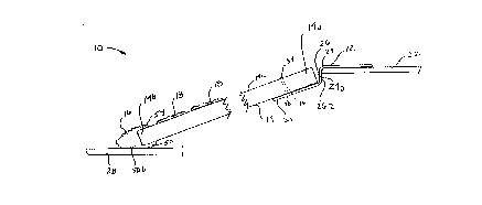
Referring now to the drawings, a po,i ~'e ramp accord.ng to the
teachings of the present invention is indicated gener;~l!y at 10 in FIGURE 1. Ramp
10 includes a support plate 12, an angled or inclined beam 14 and a foot member
16. Ramp 10 also includes one or more traction plates 18 adarted to inc,~ase ~ ~ ~ f
~, ."- " ,,~
friction along a top surface of angled beam 14. A single ramp 10 may be used in ; ' '
15 a particular apFl!~tion or alterl,a~31y one or more ramps could be used in
co~ nation. .. ,. .'~
FIGURES 2 and 3 illustrate the support plate 12 of ramp 10 in greater ~ ~
detail. As shown therein, support plate 12 is preferably a generally rec1anyular : :
plate made of any suitable strong and rigid material, such as 'steel, which has been
formed into three main portions, pref~r~bly by bending about a pair of subs~antially ~ -
parallel axes. As will be seen, the plate 12 is of a generally simple construction
'; and in a preferred form of the invention is ~",,ue.l from heavy sheet steel.

21179~6
A first portion 20 of support plate 12 is substantialiy flat and is
adapted to be disposed in a generally horizontal position when ramp 10 is in use.
Portion 20 is preferably configured so as to rest upon raised surface 22 and is of
a length l1 which is adequate to provide stable support of the ramp 10 upon raised
5 surface 22. In a preferred embodiment, length 11 is approximately 3 to 5 inches
First portion 20 of plate 12 also includes one or mors pierced holes
20a through which a nail or threaded fastener such as a self tapping screw 21 is
to be placed in order to fixedly secure first portion 20 to raised surface 22. Holes
20a may also be countersunk if desired, in order to avoid a projecting fastener
, ~,: . ,,;
10 head. Other suitable means of further securing first portion 20 to raised surface
22 could also be used. As shown in FIGURE 4, first portion 20 pre~erably also has
disposed upon a bottom surface 20b thereof, a resilient pad or mat 23 adapted to
increase friction between plate 12 and surface 22 as well as to increase stability.
In addition, the pad 23 also acts to inhibit scratching or otherwise marring the
i 5 raised surface 22. Mat 23 is preferably made of open cell neoprene rubber about
,:,. , ' .:. . ..
0.0625 inches thick and extends along the width w of support plate 12 a length i4
of apploxin~dlely 3.625 inches.
Extending from first portion 20, beyond an edge 24 of raised surface
22, is a second portion 26 of support plate 12. Second portion 26 extends
20 sul~sldn'i~'ly downwardly from first portion 20, preferably at an appro,~i"~aLely 90~
angle. First portion 20 may be disposed with respect to upper surface 22 so that
surface 26a of second portion 26 abuts and bears against a surface 24a of edge
24 in order to provide additional support thereagainst. In a preferred embodiment
wherein plate 12 is formed of sheet metal about .187 to .25 inches thick, the bend
: ~ '

21179~6
.,- ;
radius r1 between first and second portions 20 and 26, is preferably about .25
inches. As shown in FIGURE 4, a portion of mat 23 also preferably extends from
first portion 20 of support piate 12 at least halfway up second portion 26.
., , , ~,~
Extending outwardly from second portion 26, away from raised
surface 22 and toward ground level surface 28, is a third portion 30 of support -
plate 12. As shown in FIGURE 2, third portion 30 preferably extends at a generally
predetermined angle A of approximately 18~ from the plane extending from first ;
portion 20 or from horizontal, this angle of incline found generally to be suitable for '
most applications. Third portion 30 is of a length 13 which in this exemplary
embodiment is about 3 to 5 inches.
;
Third portion 30 is preferabiy adapted to support one end 14a of
angled beam 14 thereupon. Beam 1-4 is preferably rigid, suL)s~a~1 ~"y flat and
equal in width or generally no greater than the width w of plate 12. Beam 14 maybe a sturdy piece of lumber, preferably thick enough to be strong and wider than .
... ..
six inches, such as a standardly available two-by-eight or two-by-twelve board.
.
Beam 14 could alternately be formed of any other suitable material such as a metal
. ....
or hard plastic. When used with a two-by-eight piece of lumber, the width w of
plate 12 is preferably around 7.25 inches, or about 11.25 inches when beam 14 isa two-by-twelve. ;
; ~ .
First portion 30 of support plate 12 preferably includes at least one
hole 32 through which a bolt 34 may pass. Bolt 34 preferably also passes througha suitably fashioned corresponding hole 36 in beam 14 and may be held securely
therein by a suitable retaining means such as a washer and nut 38. Alternately,
6 -~

r 211 79~i6
however any other suitable fastening means for securely mounting beam 14 onto
support plate 12 may also be employed.
Support plate 12 is preferably configured so as to support beam 14
in a position like that illustrated in FIGURE 2 wherein the distance from an inside
5 bend radius R of plate 12 to a top surface of first portion 20 is substantially equal
to the thickness t of beam 14. This configuration minimizes any discontinuity d
between an upper surface of beam 14 and first portion 20 of plate 12. In a
preferred embodiment wherein beam 14 is a standard board such as a two-by~
eight or two-by-twelve this distance 12 is pre~r~bly approximately 1.5 inches.
10As shown in FIGURE 1 end 14b of beam 14 the end opposi~e that
... ....
secured to third portion 30 of plate 12 is supported along ground level surface 22 ~ ~:
by a foot member 16. Foot member t6 in the exer"plaly embodiment illustrated
in FIGURES 5 and 6 is of a substantially uniform cross section and includes three
main portions. A solid portion 50 of foot member 16 is pre~erably of a generally
15 triangular cross sectional shape. A pair of up~lan~ g support members 52 54
. ., "
extend parallelly substantially perpendicularly away from a flat side 50a or base
of triangular portion 50 and are adapted to retain and support beam 14
therebetween. Lower me"~ber 52 pre~e,ably has a body thickness t2 which is
thicker than body thickness t4 of upper n,er"ber 54 thickness t2 being
20 approximately .37 inches and thickness t4 approximately .19 inches.
In a preferred embodiment with beam 14 being a substantially flat
board the space created between triangular portion 50 and upstanding members
52 54 is generally re~1angular. The angles B and C of foot member 16 are
therefore preferably substantially right angles and end 1 4b of beam 14 is
~'', ~ ;'
, ~ ~ , ~',

21 1 7 9 5 6
positioned so as to abut surface 50a of triangular portion 50. Alternately, however,
additional means such as nails, threaded fasteners, epoxy or any other suitable ;
means could also be used to further secure beam 14 wlthin foot member 16.
The angle D of triangular portion 50 of foot member 16, as shown in
5 FIGURE 5, preferably is less than around 20~ and corresponds closely or is equal
to angle A of third portion 30 of support plate 12. As shown in FIGURE 1, side ~
50b of foot member 16 is adapted to rest upon the ground level surface 22 while ~ ~ -
beam 14 is supported between members 52 and 54 and by side 50a of triangular ' ~ ~ -
portion 50. Side 50c may be at any suitable angle E with respect to member 54, ~ ~
this angle preferably being between about 28~ to 30~. ;
Foot 16 is p(e~era~ly made of a rubber or other suitable resilient,
elastomeric material, or depending upon the .,plir~tion may alternately be made
of a less resilient material such as a metal. In one form of the invention foot 16 is
~ .
made of a rubber material being Black EPDM having a durometer of around 70
15 Shore A. In addition, foot 16 provides a cushioning effect with the ground surface
28. Foot member 16 preferably includes a plurality of protrusions or ribs 56
adapted to increase friction with ground level surface 28. Ribs 56 on remaining
side 50b of triangular portion 50 and on upstanding members 52 and 54 also
increase traction. Alte",al~,ly, hoJJcvcr, various other means to increase friction
20 and to provide lateral support to ramp 10 could also be provided on foot 16.
In the pre~el,~d embodiment of foot 16 illustrated in FIGURES 5 and
6, protrusions 56 are substantially rectangular in cross section, extend along the ~1
entire width of foot 16 and are integrally formed with foot 16. Ribs 56 preferably
have a depth d of approximately .1 inches, a width W3 of approximately .15 inches

21179~6 ;~
and are generally spaced apart a distance s of about .25 inches. As shown in the
plan view of FIGURE 6, one or more larger spaces 58 between protrusions 56,
,~
measuring preferably around .66 inches, may also be provided in order to allow ~ ~ -
space for further fastening foot 16 to beam 14, such as with nails or threaded
5fasteners placed therethrough between ribs 56.
Foot member 16 has a width w1 which is substantially equal to the ~ 5width w of plate 12, preferably about 7.25 inches for use with a two-by-eight or11.25 inches for use with a two-by-twelve. The internal dislance i between
upstanding members 52 and 54 is preferably slightly less than the thickness t of,. , " .
10the beam 14. In a preferred embodiment wherein beam 14 is a two-by-eight or
similar piece of lumber, this distance i is preferably approximalely 1.5 inches. In
one forr~ of the invention, the overall height h of members 52 and 54 is sufficient
to retain beam 14 securely therebetween by interference press fit, and prr,~rably
height h is generally between 2 to around 3 inches.
In order to provide increased traction along upper surface ~4c of
angled beam 14, one or more traction plates 18 may be attached to beam 14
intermediate foot 16 and plate 12. The plates 18 can be selectively located at
desired intervals depending upon the intended application. A pre~r," ed
embodiment of a traction plate 18 according to the present invention is shown in20FIGURES 7 and 8. Plate 18 preferably is made of a rigid metal plate, pre~e,~bly
18 gauge steel, which is subsld,llially rectangular in shape and slightly na~ow~,r
in width than the width of beam 14. In this preferred embodiment, traction plate18 has a length Lt of approximately 12 inches and a width Wt of approxi")ately 9.75
inches. Traction plate 18 further has formed therein a series of holes 60 to
. ., ~
~ ' ,'' ;;
'''''.''',"

2117~6 ~
.,., '-:
facilitate fastening to beam 14 such as by bolts, nails or any other suitable means
known to those having skill in the art.
To increase friction across plate 18 in order to provide traction, plate
18 includes a plurality of punched holes 62 disposed in a regular or random array,
5 preferably having centers spaced about .625 inches apart. Holes 62 are preferably
punched so as to leave extruded or upstanding flange portions 64 of around .3125
inches in diameter d1. The uppermost edges 64a of each upstanding portion 64
.
tapers to a small thickness of around .03 inches and thereby helps break through ~ -
,::
snow, ice or mud. However, edges 64a define a continuous circular shape and
are preferably configured so as to provide a surface taper, whereby sharp points, -
which could otherwise cut tires or shoes, are avoided.
.. . ..
~ Upstanding portions 64 in the embodiment illustrated in FIGURE 8
extend outwardly from a top surface of plate 18 at a radius r of around .4 inches.
Holes 62 are preferably positioned in regularly spaced but offset rows as shown
15 in FIGURE 7. In one form of the invention, portions 64 extend above a lower
surface 18a of plate 18 approximately .2 inches and thereby siyr,i~icarltly increase
friction in order to provide traction for wheels or shoes along inclined beam surface
14a. The diameter d2 of the punched holes 62 at the lower surface is
;
approxi" ,alely 0.5 inches. This configuration is believed advantageous for
20 dissipating snow and ice in that a sufficient volume is provided whereby snow or
ice particles can be received interiorly and exteriorly to upstanding portions 64,
with edges 64a protruding therepast to provide a traction surface.
The ramp 10 of the present invention therefore provides an improved ~ -
ramp which is portable, lightweight and suitable for use in a variety of ap~'.. ,~tions. ~ -
1 0

2 ~ 1 7 ~ ~ 6
. ,
,
Ramp 10 may be sold in kit form wherein a prefabricated plate 12, foot 16 and
traction plate 18 may be provided along with suitable fastening means and the
purchaser/user would provide his or her own piece of standard slzed lumber and
build the ramp. Variations to the dimensions of the various components of the
5 ramp could be made in order to provide for ramps of di~eren~ sizes and angle of
incline.
The foregoing discussion discloses and describes merely exemplary
, ~ .
. .
embodiments of the present invention. One skilled in the art will readily recognize
from such discussion, and from the acco",panying drawings and claims, that
10 various ch~nges and modifications can be made therein without departing from the
spirit and scope of the invention as defined in the following cla ms.
:'' ~ '. ' ~;
, . : , ~ ~;
: : .:
~,. ~' '.'
:.

Dessin représentatif
Une figure unique qui représente un dessin illustrant l'invention.
États administratifs

2024-08-01 : Dans le cadre de la transition vers les Brevets de nouvelle génération (BNG), la base de données sur les brevets canadiens (BDBC) contient désormais un Historique d'événement plus détaillé, qui reproduit le Journal des événements de notre nouvelle solution interne.

Veuillez noter que les événements débutant par « Inactive : » se réfèrent à des événements qui ne sont plus utilisés dans notre nouvelle solution interne.

Pour une meilleure compréhension de l'état de la demande ou brevet qui figure sur cette page, la rubrique Mise en garde , et les descriptions de Brevet , Historique d'événement , Taxes périodiques et Historique des paiements devraient être consultées.

Historique d'événement

Description Date
Inactive : CIB de MCD 2006-03-11
Le délai pour l'annulation est expiré 2004-10-12
Lettre envoyée 2003-10-14
Accordé par délivrance 1998-04-21
Lettre envoyée 1998-02-11
Inactive : Taxe finale reçue 1997-12-15
Préoctroi 1997-12-15
Inactive : Transfert individuel 1997-10-10
Un avis d'acceptation est envoyé 1997-09-09
Lettre envoyée 1997-09-09
Inactive : Renseign. sur l'état - Complets dès date d'ent. journ. 1997-09-02
Inactive : Dem. traitée sur TS dès date d'ent. journal 1997-09-02
Inactive : CIB enlevée 1997-08-13
Inactive : CIB en 1re position 1997-08-13
Inactive : CIB attribuée 1997-08-13
Inactive : Approuvée aux fins d'acceptation (AFA) 1997-08-08
Toutes les exigences pour l'examen - jugée conforme 1995-10-27
Exigences pour une requête d'examen - jugée conforme 1995-10-27
Demande publiée (accessible au public) 1995-05-05

Historique d'abandonnement

Il n'y a pas d'historique d'abandonnement

Taxes périodiques

Le dernier paiement a été reçu le 1997-09-26

Avis : Si le paiement en totalité n'a pas été reçu au plus tard à la date indiquée, une taxe supplémentaire peut être imposée, soit une des taxes suivantes :

  • taxe de rétablissement ;
  • taxe pour paiement en souffrance ; ou
  • taxe additionnelle pour le renversement d'une péremption réputée.

Les taxes sur les brevets sont ajustées au 1er janvier de chaque année. Les montants ci-dessus sont les montants actuels s'ils sont reçus au plus tard le 31 décembre de l'année en cours.
Veuillez vous référer à la page web des taxes sur les brevets de l'OPIC pour voir tous les montants actuels des taxes.

Historique des taxes

Type de taxes Anniversaire Échéance Date payée
TM (demande, 3e anniv.) - générale 03 1997-10-14 1997-09-26
Enregistrement d'un document 1997-10-10
Taxe finale - petite 1997-12-15
TM (brevet, 4e anniv.) - petite 1998-10-13 1998-09-23
Annulation de la péremption réputée 2002-10-14 1998-09-23
TM (brevet, 5e anniv.) - petite 1999-10-12 1999-09-20
Annulation de la péremption réputée 2002-10-14 1999-09-20
Annulation de la péremption réputée 2002-10-14 2000-09-21
TM (brevet, 6e anniv.) - petite 2000-10-12 2000-09-21
Annulation de la péremption réputée 2002-10-14 2001-09-21
TM (brevet, 7e anniv.) - petite 2001-10-12 2001-09-21
Annulation de la péremption réputée 2002-10-14 2002-09-18
TM (brevet, 8e anniv.) - petite 2002-10-14 2002-09-18
Titulaires au dossier

Les titulaires actuels et antérieures au dossier sont affichés en ordre alphabétique.

Titulaires actuels au dossier
UNIVERSAL INDUSTRIAL PRODUCTS, INC.
Titulaires antérieures au dossier
RICHARD WILLIAM FRANKEL
ROBERT LOUIS SEIGNEUR
Les propriétaires antérieurs qui ne figurent pas dans la liste des « Propriétaires au dossier » apparaîtront dans d'autres documents au dossier.
Documents

Pour visionner les fichiers sélectionnés, entrer le code reCAPTCHA :


Pour visualiser une image, cliquer sur un lien dans la colonne description du document (Temporairement non-disponible). Pour télécharger l'image (les images), cliquer l'une ou plusieurs cases à cocher dans la première colonne et ensuite cliquer sur le bouton "Télécharger sélection en format PDF (archive Zip)" ou le bouton "Télécharger sélection (en un fichier PDF fusionné)".

Liste des documents de brevet publiés et non publiés sur la BDBC .

Si vous avez des difficultés à accéder au contenu, veuillez communiquer avec le Centre de services à la clientèle au 1-866-997-1936, ou envoyer un courriel au Centre de service à la clientèle de l'OPIC.

({010=Tous les documents, 020=Au moment du dépôt, 030=Au moment de la mise à la disponibilité du public, 040=À la délivrance, 050=Examen, 060=Correspondance reçue, 070=Divers, 080=Correspondance envoyée, 090=Paiement})


Description du
Document 
Date
(aaaa-mm-jj) 
Nombre de pages   Taille de l'image (Ko) 
Revendications 1995-10-31 11 694
Abrégé 1995-10-31 1 70
Dessins 1995-10-31 5 329
Description 1995-10-31 11 806
Dessin représentatif 1998-04-20 1 4
Avis du commissaire - Demande jugée acceptable 1997-09-08 1 164
Courtoisie - Certificat d'enregistrement (document(s) connexe(s)) 1998-02-10 1 118
Avis concernant la taxe de maintien 2003-12-08 1 174
Correspondance 1997-12-14 2 75
Taxes 1996-10-14 1 33
Correspondance reliée au PCT 1995-01-12 1 27
Courtoisie - Lettre du bureau 1994-10-11 2 79
Courtoisie - Lettre du bureau 1995-11-15 1 49
Correspondance de la poursuite 1995-10-26 1 35
Correspondance de la poursuite 1995-12-13 1 34