Note : Les descriptions sont présentées dans la langue officielle dans laquelle elles ont été soumises.
WO 93/22479 ~~ ~ ~ ~ ~ ~ ~~ PCT/US93/04140
ANODE-CATHODE ARRANGEMENT FOR
ALUMINUM PRODUCTION CELLS
J
Field of the Invention
The present invention concerns a new and improved electrode assembly system
or unit for electrolytic cells used for electrolysis in molten salts,
especially for
electrolysis of alumina dissolved in molten cryolite.
Background of the Invention
The technology for the production of aluminum by the electrolysis of alumina,
dissolved in molten cryolite containing salts, at temperatures around 950' C
is more
than one hundred years old .
This process, conceived almost simultaneously by Hall and Heroult, has not
evolved as many other electrochemical processes. It is difficult to understand
why,
despite the tremendous growth in the total production of aluminum that in
fifty years
has increased almost one hundred fold, the process and the cell design have
not
undergone any gnat change or improvement.
The electrolytic cell trough is typically made of a steel shell provided with
an
insulating lining oaf refractory material covered by anthracite-based carbon
blocks at
the wall and at the; cell floor bottom which acts as cathode and to which the
negative
pole of a direct current source is connected by means of steel conductor bars
embedded in the carbon blocks.
The anodea are still made of carbonaceous material and must be replaced
every few weeks. The operating temperature is still appmximately 950' C in
order
to have a sufficiently high alumina solubility and rate of dissolution which
decreases
rapidly at lower temperatures.
SUBSTITUTE SHEET
CA 02118245 2003-02-28
_ 7
The carbonaceous materials used in Hall-Heroult cells as anode and as cell
lining are certainly not ideal for resistance under the existing adverse
operating
conditions.
The anodes have a very short life because during electrolysis the oxygen which
should evolve on the anode surface combines with the carbon to form CO= and
small
amounts of CO. The actual consumption of the anode is approximately 450 Kg/Ton
of aluminum produced which is more than 1/3 higher than the theoretical amount
of
355 Kg/Ton corresponding to that of the stoichiomecric reaction.
The carbon lining of the cathode bottom has a useful life of a few years after
which the operation of the entire cell must be stopped and the cell relined at
great
cost. In spite of an aluminum pool having a thickness of more than 20 mm
maintained over the cathode, the deterioration of the cathode carbon blocks
cannot be
avoided because of penetration of cryolite and liquid aluminum, as well as
intercalation of sodium ions which causes swelling and deformation of the
cathode
carbon blocks and displacement of such blocks.
In addition, when cells are rebuilt, there are problems of disposal of the
carbon which contains toxic compounds including cyanides:
The carbon blocks of the cell wall lining do not resist attack by cryolite,
and
a layer of solidified cryolite has to be maintained on the cell wall to extend
its life.
The major drawback, however, is due to the fact that irregular electromagnetic
forces create waves in the molten aluminum pool and the anode-cathode distance
(ACD), also called interelectrode gap (IEG), must be kept at a safe minimum
value
of approximately 50 mm to avoid short circuiting between the cathodic aluminum
and
the anode.
The high electrical resistiviry of the electrolyte, which is about 0.4
Ohm.cm.,
causes a voltage drop which alone represents more than 40 % of the total
voltage drop
with a resulting energy efficiency which reaches only 25 % in the most modern
cells.
The high incidence of the cost of energy, which has become even a bigger
item in the total manufacturing cost of aluminum since the oil crisis, has
decreased
the rate of growth of this important metal.
In the second largest electrochemical industry following aluminum, namely the
chlorine and caustic industry, the invention of dimensionally stable anodes
(DSA~)
CA 02118245 2003-02-28
1
-
which were developed around 1970 permiaed a revolutionary progress in chlorine
cell
technology resulting in a substantial increase in cell energy efficiency, in
cell life and
in chlorine caustic purity.
The substitution of graphite anodes with DSA~ increased drastically the life
of the anodes and reduced substantially.the cost of operating the cells. The
rapid
increase in chlorine caustic growth was stopped only by ecological concerns.
In the case of aluminum production. pollution is not due to the aluminum
produced, but to the materials used in the process and to the primitive cell
design and
operation which have remained the same over the years.
Progress has been made in the operation of modern plants which utilize cells
where the gases emanating from the cells are in large part collected and
adequately
scrubbed and where the emission of highly polluting gases during the
manufacture of
the carbon anodes is carefully controlled.
However, the frequent substitution of the anodes in the cells is still a
clumsy
and unpleasant operation. This cannot be avoided or greatly improved due to
the size
and weight of the anode and the fact that the cathode is formed by the cell
floor and
is not removable during cell operation. Recently, progress has been made in
the
anode and the cathode composition, primarily with the development of non-
carbon,
substantially non-consumable anades (NCA) and cathodes (NCC). The life of
these
NCA and NCC is nevertheless limited and even these electrodes need occasional
replacement or reconditioning.
Background Art
US-A-4560448-Sane et al discloses a recent development in molten salt
electrolysis cells concerning making materials wettable by molten aluminum.
However, the carbon or graphite anodes are of conventional design with no
suggestion leading to the present invention.
US-A-4681671-Duruz illustrates another improvement in molten salt
electrolysis wherein operation at lower than usual temperatures is carried out
utilizing
permanent anodes, e.g. metal, alloy. ceramic or a metal-ceramic composite as
disclosed in EP-A- 0030834 and US-A-4397729.
CA 02118245 2003-02-28 I
While improved operation is achieved at lower temperatures, there is no
suggestion
of the subject matter of the present invention.
WO 89106289 - La Camera et al deals with molten salt
electrolysis wherein attention is directed to an electrode having increased
surface area.
However, again. there is no disclosure leading to the present invention.
The following references disclose several other proposals to improve cell
operation:
EP-A- 0308015 de Nora discloses a novel current collector:
EP-A- 0308013 de Nora deals, with a novel composite cell bottom: and
EP-A- 0132031 Dewing provides a novel cell lining.
EP-A-0126555 discloses an electrolytic cell and method.
US-A-4737247 discloses apparatus and method for providing a support mechanism
for electrode assemblies for the production of aluminum.
While the foregoing references indicate continued efforts to improve the
operation of molten cell electrolysis operations, none deal with or suggest
the present
invention.
Su~,r~rnarv of the Invention
This invention aims to overcome problems inherent in the conventional
operation of electrolysis cells used in the production of aluminum via
electrolysis of
alumina dissolved in molten cryolite.
The invention pernnits more efficient cell operation particularly by modifying
the electrode configuration, the materials of construction, and by utilizing a
multi-
double-polar cell employing a new method of operating the cell by means of the
removal and reimmersion of an anode-cathode double-polar electrode assembly
system
which, according to the invention. forms a single assembly. This assembly can
be
removed from the cell as a unit whenever the anode and/or the cathode or any
part
of the electrode assembly unit needs reconditioning for good cell operation.
The invention proposes a single anode-cathode double polar electrode assembly
system or unit including at least two assembly units of anodes and cathodes
connected
to a single source of electrical direct current. the assembly system being
removable
CA 02118245 2003-02-28
or immersible or reimmersible as such into the molten electrolyte during
operation
of the electrolysis cell.
In particular the invention concerns an anode-cathode double-polar electrode
assembly forming an anode-cathode electrode assembly system or unit of a new
configuration to be utilized in multi-double-polar cells or continuous double-
polar
configurations for the production of aluminum, by the electrolysis of alumina
dissolved in cryolite based molten salts.
In this assembly, the anode and cathode materials are electrically conductive
and their surface or coating is resistant to the electrolyte and to the
respective
products of electrolysis. The anode-cathode gap is maintained substantially
constant
and the anode and the cathode are held together by means of connection
elements
made of material of high electrical, chemical and mechanical resistance, thus
permitting the removal from and reimmersion in the molten electrolyte of a
double-
polar electrode assembly unit during operation of the multi-double-polar cell
for the
production of aluminum whenever the anode and/or the cathode or any part of
the
electrode assembly unit may need reconditioning for efficient cell operation.
In the anode-cathode double-polar electrode assembly units the anode and the
cathode surfaces may be substantially parallel in configuration whereby the
current
density across the gap is completely balanced. On the other hand, the anode-
cathode
gap has different values along a line at a 90° angle with respect to
the current
path in order to balance the voltage drop in difference current paths and so
as to
maintain a more uniform current density over the entire active surface area of
the
electrodes. The lines of current path may of course be changed to be at any
angle
to the horizontal or vertical directions, i.e. substantially vertical,
substantially
horizontal or at an angle with the vertical.
The invention contemplates using a package, i.e., a plurality of spaced apart
anodes and cathodes connected by suitable electrically insulating means such
as a bar
or insulating layer The number of anode-cathode combinations in a package can
be
varied as desired; generally from 4 to 100 are considered practical.
The electrical contacts in such double-polar electrode assembly units or
packages may taken on different configurations. For example the electrical
contacts
to the anode and cathode of the double-polar electrode assembly unit may be
both
WO 93/22479 PC~/US93/04140
made from the top of the mufti-double-polar electrode assembly unit may be
made
from the top and that to the cathode may be made from the bottom.
In the double-polar electrode assembly unit the anodes may be made of porous
material for greater active surface area and better evolution of the gas
produced.
Similarly the double-polar electrode assembly unit may contain cathodes made
of porous materials for better drainage of the aluminum produced. In fact
porous
materials may be used for the anodes, the cathodes; and/or for the non-
conductive
connections for better chemical and mechanical resistance.
Advantageously, the gas evolution and its guided displacement is utilized for
better electrolyte circulation in the space between the anode and cathode
active
surfaces.
Additionally the anodes of the anode-cathode double-polar electrode assembly
unit may be made from non-carbon, substantially non-consumable refractory
materials
resistant to the electrolyte, to the oxygen produced, and to other gases,
vapors, and
fumes present in the cell. Such refractory materials normally may be selected
from
the group consisting of metals, metal alloys, intermetallic compounds and
metal-
oxyborides, oxides, oxyfluorides, ceramics, cermets, and mixtures thereof. The
anode materials may also be made from metals, metal alloys, intermetallic
compounds
and/or metal-oxycompounds which contain primarily at least one of nickel,
cobalt,
aluminum, copper, iron, manganese, zinc, tin, chromium and lithium and
mixtures
thereof. Oxides and oxyfluorides, borides, ceramics and cermets which contain
primarily at least one of zinc, tin, titanium, zirconium, tantalum, vanadium,
lithium.
cerium, iron, chromium, nickel, cobalt, copper, yttrium, lanthanides, and
Misch
metals and mixtures thereof may be also used. Adherent refractory coatings may
be
coated on anodes comprising an electrically conductive structure.
The cathodes may be made of or coated with an aluminum-wettable refractory
hard metal (RHM) with little or no possibility of molten cryolite attack. The
refractory hard material may be a borides of titanium, zirconium, tantalum.
chromium, nickel, cobalt, iron, niobium, and/or vanadium. Thus, the cathode
may
comprise a carbonaceous material, refractory ceramic, cermet, metal, metal
alloy,
intermetallic compound or metal-oxycompound having an adherent refractory
coating
SUBSTITUTE SHEET
CA 02118245 2003-02-28
7 _
made of an aluminum-wettable refractory hard metal fRHM). The carbonaceous
material could be a anthracite based material or carbon or graphite.
Doping agents may be added to the anode and cathode materials to improve
their density, electrical conductivity, chemical and electrochemical
resistance and
other characteristics.
All the materials mentioned above may be made by micropyretic reactions
described in an earlier US patent US 5,310,476:.
The connections utilized to bind the anode to the cathode to form a single or
multiple double-polar anode-cathode electrode assembly may be made of any
suitable
electrically non-conductive material resistant to the electrolyte and the
products of
electrolysis. These include silicon nitride. aluminum nitride and other
nitrides as well
as alumina and other oxides, and oxynitrides.
Micropyretic reactions starting from slurries may become the methods of
making the anode-cathode double-polar electrode assembly systems The slurries
may
contain reactant and non-reactant fillers. The non-reactant fillers may
contain
particulate powders made of materials obtainable by the micropyretic reaction.
Micropyretic methods may be utilized to form the double-polar or multi-
double-polar asscmblies in a single operation.
Multi-double-polar cells and packages are also contemplated containing two
or more anode-cathode double-polar single electrode assembly units. The multi-
double-polar cells could have plates. cylinders or rods to optimize the
voltage
efficiency and work within the current density limitations of the materials
being used.
For instance, the anodes can be substantially cylindrical hollow bodies and
the
cathodes can be rods placed inside such bodies. As stated before, porous
materials
may be employed. Methods of operating such cells are also envisaged with
various
configurations of anodes and cathodes in rod. V or cylindrical formation For
instance, the anodes can have the shape of an inverted V and the cathodes have
the
shape of a prism placed inside the anodes.
All the assemblies are contemplated to be environmentally superior to current
designs as the amount of CO~ and CO emissions are minimized to avoid pollution
problems which disturb the atmosphere and which delay the growth or production
of
WO 93/22479 y ,~ ~s;; PCT/US93/04140
',~ ~. '~,. ,~ o.,e
,*, . - -
aluminum. Computer monitoring of electrode gaps is also envisaged. All the
assemblies described herein are expected to be immersible and/or reimmersible
in the
electrolyte. A continuous replacement strategy for the electrodes is also
envisaged.
Brief Description of the Drawings
Reference is made to the drawings wherein:
Figure 1 is a schematic drawing of a molten salt electrolysis cell
illustrating
both a conventional anode and packages of anodes and cathodes employing this
invention.
Figure 2 is a schematic drawing of an anode-cathode double-polar cell
utilizing
a porous cathode.
Figure 3 is a schematic drawing of another form of double-polar cell utilizing
a porous cathode.
Figure 4 is a schematic drawing of another anode-cathode configuration.
Figure 5 is a schematic drawing of another configuration where the anode
active surface area is continuously replaceable.
Detailed Description of the Drawings
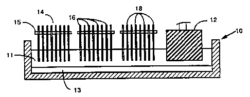
Referring to the drawings, in Figure 1 there is shown an electrolytic cell 10
containing molten cryolite 11 and aluminum 13 and containing both a
conventional
pre-baked carbon anode 12 as well as three removable anode-cathode packages 14
of
this invention comprising alternate anodes 16 and cathodes 18 held in spaced-
apart
relationship by a transverse electrically insulating bar 15. The anodes and
cathodes
can be closely spaced to improve cell voltage and energy efficiency and
overall good
cell operating conditions. The anode-cathode removable units or packages 14
offer
substantially greater electrochemical active surfaces compared to currently
employed
anodes such as 12. Moreover, the electrically insulating bar 15 can be
designed to
be continuously adjustable to insure optimum distance and best performance.
In Figure 2 there is shown an anode-cathode double-polar cell 20 containing
molten cryolite 22, aluminum 23 and an anode-cathode assembly system 24
consisting
of an anode 26 and a porous cathode 28 separated by mechanically strong
electrically
SUBSTITUTE SHEET
CA 02118245 2003-02-28
_g_
insulating material 27 resistant to attack by molten cryolite. The pieces of
materials
27 serve both as means for suspending the porous cathode 28 and as spacers
leaving
between the facing anode and cathode surfaces a space containing the
electrolyte, or
the insulating material 27 could form a porous diaphragm with pores of
sufficient
size. Elecuolysis circulation can be induced in the anode-cathode gap. In
operation,
cathodically-produced aluminum drips through the pores in cathode 28, and
drips into
the pool aluminum 23.
A preferred anode-cathode double-polar electrode assembly is as sec forth in
Figure 3. In Figure 3 there is shown an anode-cathode double-polar cell 30
containing molten cryoiite ~32 and molten aluminum 34. The anode-cathode
double-
polar single electrode assembly 36 includes an anode 38 and a porous cathode
40.
One or more horizontal insulating bars 42 separates the anode 38 and cathode
40, the
cathode 40 having a U-section as shown and being suspended from the insulating
bars) 42. Note that the insulating bar 42 holding the anode 38 and cathode 40
together is above the cryolite. The cathode 40 also may be formed of materials
containing a plurality of holes.
Figure 4 illustrates an anode-cathode configuration which can be fitted in a
conventional aluminum production cell or in a cell of completely new design.
In this
design, carbon prisms of inverted V shape or wedges 50 are fitted on a carbon
cell
bottom 52, preferably fixed thereon by bonding when the cells is being built
or
reconstructed. These carbon wedges 50 have inclined side faces, for instance
at an
angle of about 45° to 10° to the vertical, meeting along a top
ridge 54. The wedges
50 are placed side by side, spaced apart at their bottoms to allow for a
shallow pool
56 of aluminum on the cell bottom 52.
The ridges 54, which can be rounded, are all parallel to each other across or
along the cell and spaced several centimeters below the top level of the
electrolyte 58.
The inclined side faces of the wedges 50 can be coated with a permanent
dimensionally stable aluminum-wettable coating, preferably one produced by a
micropyretic reaction. The application of micropyretic reactions to produce
electrodes for electrochemical processes, in particular for luminum production
is the
subject of co-pending USpatents 5,217,583, 5,316,718 and US 5,364,442.
i
CA 02118245 2003-02-28
-10-
Over the cathode-forming wedges 50 are fitted anodes 60, each formed by a
pair of plates which together tit like a roof over the wedges 50, parallel to
the
inclined surfaces o,f the wedges 50, providing an anode-cathode spacing of
about 10
to 60 mm, preferably 15 to 30 mm. At their tops, the pairs of anode places 60
are
joined together and connected to a positive current supply. Holes are provided
towards the top of the anode fur better escape of the gas evolved and useful
electrolyte circulation. The anode plates 60 are made of or coated with any
suitable
non-consumable or substantially non-consumable, electronically-conductive
material
resistant to the electrolyte and to the anode product of electrolysis, which
is normally
oxygen. For example, the plates may have a metal, alloy or cermet substrate
which
is protected in use by a cerium-oxyfluoride-based protective coating produced
and/or
maintained by maintaining a concentration of cerium in the electrolyte, as
described
in US-A-4614569.
Other refractory surfaces on carbonaceous or refractory substances can be
produced by the methods des~tibed in U.S. ~5,310,476~:
Adjacent pairs of anode plates 60 and their cathode wedges 50 are assembled
together as units by an adequate number of horizontal bars 65 of insulating
material,
suspended from one or more central insulating posts 67. By this means, the
entire
unit can be removed from and replaced in the cell when required.
In all cases, the current flow is, of course, from anode to cathode through
the
molten cryolite. In utilizing an anode-cathode double-polar electrode assembly
of this
invention, the voltage and energy efficiency can be singularly improved since
the
anode-cathode spacing can be minimized and significant numbers of assemblies
put
together to provide high efficiency while permitting easy removal of the anode-
cathode double-polar electrode assembly during cell operation from the molten
electrolyte and rglmmersion thercin.
Since no conventional massive carbon anode is required, the electrode
assembly of this invention can be significantly lighter in weight than
conventional
anodes. further, the materials of fabrication and technique of construction
are readily
available and can be produced and utilized in large quantities using
relatively
WO 93/22479 ~ '~ '1 ~~', ~ PCT/US93/04140
~.:.~~v~.~
- 11
inexpensive procedures. Since the anode-cathodes double-polar electrode
assembly
can be formed of various configurations, it is available to retrofit existing
aluminum
production cells with all the advantages set forth herein.
Figure 5 iillustrates another embodiment of the invention disclosing a cell
S trough containing cryolite '72, aluminum 73, an upwardly-curved cathode
section 74
and a correspondiing downwardly curved anode 76. The cathode has a central
opening into which the produced aluminum can drain. The anode 76 can consist
of
flexible wire or a bundle of flexible wires or can be in the form of a
flexible sheet.
The anode and cathode are made of materials as previously described herein.
As shown, the anode 76 can be replaced continuously, e.g. by rotation, or at
predetermined intervals as desired. The or each insulating bar 75 in this case
has
holes for the movement of the anode. This configuration is called the
continuous
double-polar construction.
The insulating bar 75 may be above or below the cryolite line. The insulating
bar 75 serves to guide and space the anodes) 76 from the cathode 74. There can
be
several insulating lbars 75 across the cell, and bars 75 at different levels.
By means
of the central upwardly prajecting post or extension 77, the insulating bass
75 can be
lifted out of the cell with its associated anodes 76 and cathode 74, for
servicing when
required.
Many of these continuous electrode assemblies or units can be set side by side
in an electrolytic cell.
It will be widerstood that the anode-cathode electrode assembly can have other
configurations such as cylindrical bodies (or of other shaped open cross
section)
wherein, e.g. the anodes are formed to surround cathodes which are solid (or
hollow)
cylinders or of other cross sectional shape.
Further, whatever configuration is used, the anodes and/or cathodes can be
provided with cooling means, e.g., internal fluid conduits to contain and
permit the
flowthmugh of coolants.
In the practice of operating a multi-double-polar cell for the electrowinning
of
aluminum, it is one of the advantages of this invention that one anode-cathode
unit
or a package of anode-cathodes can be removed from the molten electrolyte
while the
cell is in operation and replaced by another anode-cathode unit or package.
This
SUBSTITUTE SHEET
I
CA 02118245 2003-02-28
-12_
provides a singular improvement over conventional molten cell anode
replacement
operations. Further, this invention permits monitoring of anode-cathode
performance
under computer control to permit automatic removal of a faulty anode-cathode
package and automatic reimmersion of a new or renovated anode-cathode package.
It is further feature of this invention that the anode-cathode gap can be
maintained constant oc made variable. e.g.. where any towering of the
electrolyte
bath electrical conductivity which occurs 'due ~ .to change in electrolyte
bath
composition or drop of the operating temperature can wholly or partially be
' ~comperi~ated by decreasing the anode-cathode gap within limits permitted by
an
acceptable current efficiency.
The materials used to form the anode-cathode can be and preferably are.
porous, or contain a plurality of holes.
The anodes preferably are substantially non-consumable refractory materials
resistant to the oxygen produced and the ocher gases, vapors and fumes present
in the
cell, and resistant to chemical attack by the electrolyte.
Useful refractory materials include metals, metal alloys, intermecaliic
compounds, metal oxyborides, oxides, oxyfluorides, ceramics, cermets and
mixtures
thereof. In the case of the metals, metal alloys, intettnetallics and/or metal-
oxycompounds, it is preferred that the component metals be selected from at
least one
of nickel, cobalt, aluminum, copper, iron, manganese, zinc, tin. chromium.
lithium.
and mixtures in a primary amount, i.e., at least 50% by weight.
In the case of oxides, oxyfluorides, borides, ceramics and cermets, it is
preferred that they contain a primary amount, i.e.. at least 50% by weight, of
at least
one of zinc, tin, titanium, zirconium, tantalum, vanadium, lithium, cerium,
iron.
chromium, nickel, cobalt, copper, yttrium, lanthanides, Misch metals and
mixtures
thereof.
The cathodes can be formed of or coated with an aluminum-weaable refractory
hard metal (RHM) having little or no solubility in aluminum and having good
resistance to attack by molten cryolite. Useful RHM include borides of
titanium.
zirconium, tantalum, chromium, nickel, cobalt, iron. niobium andlor vanadium.
Useful cathode materials also include carbonaceous materials such as
anthracite. carbon or graphite.
CA 02118245 2003-02-28
-13-
It is preferred that such a material be coated with a RHM. Further
information on RHM coatings is set forth in U.S. Patent .5,310,476.
The anode and cathode materials or at least their surfaces may also contain a
small but effective amount of a dopant such as iron oxide, lithium oxide, or
cerium
oxide to improve their density, electrical conductivity, chemical and
electrochemical
resistance and other characteristics.
Reference is now made to two examples of specific embodiments of the
invention.
Examgle 1
A cell in the new configuration shown in Figure 1 was run in a small bath at
960°C containing molten cryolite. The anode plate material was made of
a nickel
alloy and the cathode plate was made from anthracite coated with a TiB,
coating.
The anode and cathode distance in the double-polar configuration was kept at
10 mm.
Cell voltage was 3 .1 V at a current of ~1 A which translates to a current
density of
0.? A/cm2. The anode-cathode double-polar assembly is removed after 4 hours,
cleaned to regenerate a fresh anode surface, the gap adjusted to 10 mm and the
assembly reimmersed. The cell voltage returns to the original value of 3.1 V
at the
same current. The test of removing and further reimmersion was carried out 24
times
to establish the concept of the double-polar cell. The insulating bar in this
test was
made out of alumina.
EatartZ~le 2
An electrode assembly in the configuration of Figure 3 was made and tried as
a anode-cathode double-polar electrode assembly. The anode was a solid block
of
nickel aluminide _and the porous cathode was made of Ti&. Stable and constant
conditions were noted at a current density of 0.7 . Alcm2 with an average
anode-
cathode gap of 15 mm. This system was removed and reimmersed once every hour
for 24 hours and a stable and constant cell voltage of 3.4 V was measured each
time.
The insulating bar in this test was made out of alumina.
WO 93/22479 ~.~ c? ~yj PCT/US93/04140
In conclusion, it has been shown that new anode-cathode double-polar
assemblies are possible and advantageous.
SUBSTITUTE SHEET