Note : Les descriptions sont présentées dans la langue officielle dans laquelle elles ont été soumises.
- -2- r 2 1 1 8 4 1 ~
APPARATUS FOR TREATING FIBER SUSPENSION
The present invention relates to an apparatus for treating fiber suspension. Said
apparatus is especially applicable for screening and also thickening pulp in thewood processing industry. More precisely the inventive concept of the
5 apparatus of the invention is related to the pulse member construction of the
screen or thickener being used.
There are in principle two known pulse member types, which both are generally
used and the purpose of which is, as known, to maintain the screen surface
clear, in other words, to prevent the formation of a fiber matting on the screen10 surface. One type is exemplified, for example, by a rotor embodiment in
accordance with US Patent 4,193,865, in which a rotor is rotatably mounted
within a stationary screen cylinder, comprising blades located close to the
surface of the screen cylinder. Said blades form an angle with the axis of the
cylinder in the embodiment of said patent. The screen surface is subjected to
15 pressure pulses by the moving blades clearing the openings of the screen
surface. There are embodiments that have blades on both sides of the screen
cylinder. Consequently, the suspension being treated is fed either to the insideor to the outside of the cylinder and the accept is discharged from the outside
or from the inside of the cylinder, respectively.
20 In a European Patent Application EP-A-O 436 888 there is disclosed a pressurescreen apparatus having a foil-type rotor. The foils of the rotor are fastened
either on the shaft of the rotor or on a cylindrical rotor surface. The foils have
a leading surface, a surface substantially parallel to the screen cylinder and asloping trailing surface. The leading surface is provided with grooves in
25 circumferential direction. The grooves are formed of side surfaces and a
bottom surface. The bottom surface forms an acute angle with the screen
cylinder whereby the crossectional area between the groove and the screen
cylinder reduces towards the trailing surface of the foil. Thus the bottom
surface creates a zone of increased pressure forcing fiber suspension through
30 the screen cylinder openings. In a corresponding manner, the sloping trailing
~ 211841 0
-3-
surface creates a zone of reduced pressure at the back side of the foil whereby
the screen cylinder openings are backflushed.
Another type worth mentioning is, for example, one in accordance with US
Patent 3,437,204, in which the rotor is a substantially cylindrical closed body,5 the surface of which is provided with almost hemispherical protrusions, so
called bulges. In said apparatus the pulp is fed to a treatment space between
the rotor cylinder and the screen cylinder outside thereof, whereby the
protrusions of the rotor, the bulges, act both to press the pulp against the
screen cylinder and to draw off the fiber flocs from the perforations of the
10 screen cylinder with the trailing edge. Because this kind of construction has a
highly thickening effect on the pulp, there are in the above mentioned
arrangement three dilution water connections arranged at different heights on
the screen cylinder, so as to make the screening of fiber suspension take place
satisfactorily. A corresponding "bump rotor" type is disclosed also in US Patent15 3,363,759.
Also, other embodiments of the above mentioned cylindrical rotor are known,
in connection with which many kinds of protrusions in the screen cylinder side
may be considered to be used as disclosed in different publications.
DE application 30 06 482 discloses a knot separator, in which on the surface
20 of a cylindrical rotor drum there are plough-like protrusions, made of plate
material, by which the pulp between the rotor and the screen cylinder is
subjected to strong mixing forces so as to make fibers pass through the screen
cylinder most effectively, and knots, shives and such separate therefrom.
US patent 3,400,820 discloses a rotor being formed of eccentric portions or
25 lobes. The slope of the fluid contacting surface of the rotor is gradual in the
increasing as well as decreasing clearance regions. The slope angle is less than15 relative to the direction of the movement. Since the slope is equal in both
directions the operation of the rotor is far from optimal. The decreasing
clearance presses the pulp towards the screen surface such that the openings
~ 2~ ~84~ ~
of the screen cylinder easily clog, whereby the portion having the increasing
clearance is not able to create a negative pressure sufficient to draw the fiberagglomerations out of the openings. Yet another drawback of the structure
shown in the patent is, on the one hand, its tendency to crush all the impurities
5 like knots etc. between the rotor and the screen surface. On the other hand,
if the impurities are hard, such as stone or metal particles, there is a risk that
the rotor presses the particles through the screen cylinder.
US Patents 4,188,286 and 4,202,761 disclose a screen apparatus, in which
there is a rotatable cylindrical rotor inside the screen cylinder. There are
10 protrusions arranged on the rotor on the screen cylinder side, which protrusions
have a V-shaped axial cross section so that on one rotational edge of the rotor
there is a surface coming closest to the screen cylinder and being parallel to
the rim of the rotor, and having an end surface substantially perpendicular to
the surface of the rotor. These protrusions are arranged on the surface of the
15 rotor cylinder axially in a certain angle position so that all protrusions of the
rotor are in the same disposition with respect to the shaft of the rotor.
According to the prior publications pulp can be fed to this apparatus to either
side of the screen cylinder. If pulp is fed to the outside of the screen cylinder
and accept is discharged from the interior of the screen cylinder, in other
20 words from the rotor side, the rotational direction of the rotor is such that the
accept is subjected by the angle position of the protrusions to a force
component directed downwards and that the said inclined/ascending surface
operates as a front surface. If, however, pulp is fed between the rotor and the
screen cylinder, in other words the accept is discharged from exterior of the
25 screen cylinder, the rotational direction is opposite to the former. The
protrusions tend to slow down the downward pulp flow and the surface
upright to the surface of the rotor cylinder operates as a front surface.
Practical experience in the industry has, however, proved that the above
mentioned apparatus arrangements do not operate satisfactorily in all
30 circumstances. The apparatus also tends to dilute the accept and is therefore
f 'A
5 ~a ~ ~ ~ 4 1l ~
not applicable in cases where pulp with constant consistency is needed.
Because the foils in the foil rotors are considerably far apart (4 to 8 foils), fiber
matting will always form on the screen cylinder before the next foil wipes it
off. Thus the use of a screen is not efficient. Moreover, the said rotor type is5 expensive to produce because of the accurate dimensioning requirements of
the rotor and the careful finishing of it. The ability of the foil to wipe off the
fiber suspension, which accumulates on the surface of the screen cylinder is
relatively poor. Further, the conventional foil resembling a wing of an aeroplane
of its cross-section causes problems in the screening. It has been noted that
10 the curved front edge, which is flow-technically appropriately designed causes
the suspension to be treated to clog between the foil and the screen surface,
in other words it causes a strong pressure stroke, due to which also impurities,such as shives tend to penetrate the openings of the screen surface. In order
to be able to draw off such shives which are pressed with high pressure to the
15 openings, a very strong negative pressure pulse is required for this purpose.
It is typical of all above described pulse members that when aiming at the
increase of the screener capacity, for example, by using higher pressure
differences or when aiming at the increase of the purity of the accept by
diminishing the size of the perforation or slot one comes to a point where the
20 screen cylinder tends to clog. The problem is thus maintaining the screen
cylinder clear, the ensuring of which offers the opportunity to optimize other
factors connected to the screening, which, however, the following patent well
illustrates. The most developed embodiment presently available in the market
is a method in accordance with Fl Patent 77279 and an apparatus realizing
25 said method. It is characteristic of the method in accordance with said patent
that the fiber suspension is subjected to axial forces varying in strength and
effective direction, the direction and strength of which depend on the axial
position between the effective point and the counter surface of the screen
cylinder, and which are used to change the axial speed profile of the fiber
30 suspension yet maintaining the direction of the flow continuously towards the discharge end.
~2 ~ 9 8 4 ~ ~
_ --6--
Better screening results are obtained with the above described apparatus than
the previous prior art apparatuses, in other words capacity, clarity, etc.
according to the need. However, said apparatus is also liable to problems,
when it is tended to utilize the most of the characteristics thereof.
5 The present invention relates to a pulse member of a screener, which has the
characteristic feature of subjecting the screen surface to a pulse clearing saidscreen surface without allowing the pressure effect "slip away" past the point
being cleaned. It is also characteristic of the pulse member in accordance with
the present invention that the pulse clearing the screen surface is the stronger10 the thicker the matting is or the worse the screen surface is clogged.
It is characteristic of an embodiment of the apparatus in accordance with the
present invention being provided with a pulse member having a continuous
surface on the screen cylinder side, and of which screen cylinder and pulse
member at least one is rotatably mounted to the shaft that the surface of the
15 pulse member on the screen cylinder side is provided with several channels
substantially parallel to the rim of the cylinder and extending of their cross-
section, and which channels generate a strong suction effect on the surface
of the screen cylinder in order to maintain the surface clear.
It is also characteristic of a second embodiment of the apparatus in accordance
20 with the present invention that the pulse member is a foil, the continuous
surface of which on the screen cylinder side is provided with members
extending close to the surface of the screen cylinder.
The apparatus in accordance with the present invention is described more in
detail below, by way of example, with reference to the accompanying
25 drawings, in which
Fig. 1 is a sectional view of a screening or thickening apparatus, which the
pulse member arrangement in accordance with the invention is intended for;
Figs. 2 a - d illustrate partial sectional views of prior art rotors;
~2~4!1~
--7--
Figs. 3 a - j illustrate preferred embodiments of pulse members in accordance
with the present invention;
Figs. 4 a - 9 illustrate other preferred embodiments and mutual arrangements
of pulse members in a screening device in accordance with other embodiments
5 of the present invention;
Figs. 5 a - b illustrate further preferred embodiments of pulse members in
accordance with the present invention;
Fig. 6 is a graph showing the accept flows of pulp as a function of pressure
difference when comparing a rotor in accordance with Fig. 4c with a
10 conventional rotor illustrated in Fig. 2a; and
Fig. 7 is a graph showing the energy consumption as function of pressure
difference when comparing the rotor in accordance with Fig. 4c with a
conventional rotor illustrated in Fig. 2a.
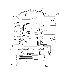
A screen apparatus 1 in accordance with a preferred embodiment comprises
15 according to Fig. 1 an outer casing 2, conduits 3, 4 and 5 for the incoming
pulp, accept and reject, respectively; a stationary screen cylinder 6; a
substantially cylindrical or possibly conical rotor 7 and a shaft 8 thereof withdrive means 9. The screen cylinder 6 may be in principle of any of the
previously known type, but the best results in most cases are achieved by
20 using a contoured screen cylinder according to Fl Patent 67588. The apparatusin accordance with the drawing operates mainly in such a way that the fiber
suspension is fed in through conduit 3, from where it flows to a gap between
the screen cylinder 6 and the rotor, more generally, a pulse member 7, to a so
called treatment space. More generally, the pulp to be treated flows to the
25 space on the pulse member side of the screen cylinder, in other words, the
pulse member is located in a space having pulp to be treated therein. The
accept which has flowed through the openings of the screen cylinder -
naturally the filtrate if a thickener is in question - is removed from conduit 4and down to the lower end of the annular gap between screen cylinder 6 and
30 rotor 7 and from there the pulp which has flowed off is discharged from reject
conduit 5. It is also appreciated from Fig. 1 that the surface of the rotor 7 onthe screen cylinder 6 side is provided with members or elements 10, the shape
A
4 ~ ~
--8--
of which may vary, for example, in a manner illustrated in Fl patent 77279
according to in which zone, in other words, in which axial part of the rotor
they are located.
The pulse member illustrated in Fig.1, which is rotationally symmetric, usually
5 cylindrical, but sometimes also conical, double conical or like, may be replaced
in some cases also with a so called blade or foil apparatus, which means that
practically the whole interior of the screen cylinder is filled with suspension.The pulse member is thus formed by foils mounted on the shaft by means of
arms and the foils extend close to the screen surface so that fiber suspension
10 is allowed to flow underneath the foil. Usually the distance of the foils from the
screen surface is significantly smaller than, for example, that of the members
illustrated in Fl patent 77279.
Fig.2 illustrates different surface types of the pulse member P known from the
prior art. Fig. 2a illustrates a foil 20, arm 22 and a portion of the screen
15 cylinder 6 in accordance with the above described foil rotor, for example, USpatent 2,835,173. The rotational direction of the foil is illustrated with an
arrow A, as also that of the other pulse members discussed in this connection.
Alternatively, arrow B drawn with a broken line points out the direction, to
which the screen cylinder 6 rotates, if the pulse member P is stationary. The
20 leading edge 24 of the foil 20 directs a pressure stroke towards the screen
surface 6, due to which both the accept pulp and also the reject particles in the
pulp tend to flow through the screen cylinder 6. The trailing surface 26 of the
foil 20 terminating to the trailing edge of the foil again causes a suction effect
on the screen surface 6, by means of which the impurities possibly stuck on
25 the screen surface are tended to be removed therefrom. However, since the foil
20 usually extends over the whole length of the pulse member, it is possible
that the suction effect in a way axially moves to an area where the counter
pressure over the screen is at its lowest, i.e. where the screen surface is alsoalready otherwise open. On the other hand, it is not possible to increase the
30 intensity of the negative pressure pulse generated by the foil by increasing the
rotational speed of the foil or by increasing the inclination, because the power
. 2~ ~4~ ~
g
consumption increases almost by the square of the speed and the mechanical
stress on the screen cylinder directly relative to the speed.
Fig. 2b illustrates a protrusion 30 of a so called bump rotor, which is shaped
as a spherical cap and which merely due to its shape directs a considerably
5 weak pressure pulse to the screen surface with its leading surface 32 and
respectively a similar weak suction pulse on the trailing surface 34. Moreover,
the shape of the bulge leads the suction pulse to the free sides, where the
pressure pulse easily dies out.
Fig. 2c illustrates a pulse means 40, a so called bulge of a rotor illustrated, for
10 example, in US patent 5,000,842, which bulge by means of a front surface 42
both accelerates the circumferential flow velocity of the pulp and subjects the
screen surface to a positive pressure pulse and draws off with the trailing edge44 fibers stuck to the screen surface 6.
Fig. 2d illustrates yet another rotor embodiment 50, which is illustrated, for
15 example, in US patent 4,981,583. Said pulse member generates with a front
surface 52 a positive pulse for a short time, by which the accept is pressed
through the screen cylinder 6 and a negative pulse for a longer time, by which
fibers are drawn off from the screen surface.
It is characteristic of all the above mentioned embodiments of Figs. 2a - 2d
20 that a stronger pulse cleaning the screen surface might be possible than whatis used today, but it would then be necessary to bring the pulse member so
close to the screen surface that it would cause problems. Foreign objects
entering the screening apparatus, such as nuts, gravel and knots, would break
the screen cylinder when entering the space between the pulse member and
25 the screen cylinder. When the distance between the front surface and the
screen cylinder is small fibers would also flow to the openings of the screen
surface so vigorously that their removal would only be possible with a
mechanical scraper.
~ -10- F~ ~ 7 ~ ~1 0
Figs. 3a - 39 exemplify a pulse member P with the pulse means 40 illustrated
in Fig. 2c. The trailing surface 44 which is important for the cleaning of the
screen surface of the pulse element, i.e. bulge 40 of the pulse member and
also the axially spaced side faces of the surface 46 parallel to the screen
5 surface 6 are provided with wings 48 extending according to this embodiment
significantly closer to the screen surface than surface 46. The purpose of the
side plates 48 is to prevent the suction pulse generated by the trailing surface44 and also partially by the surface 46 from escaping to the sides of the bulge
40 so that the suction pulse practically completely hits the screen surface,
10 which is the mere purpose of said suction pulse. Fig. 3d is a front view of abulge in accordance with Fig. 3a. The intensity of the suction pulse is in
practice directly proportional to the relation of the surface area between the
surface 46, side plates 48 and screen surface 6 to the cross-sectional surface
area of a flow channel which the trailing surface 44 at each time encounters.
15 In other words when the cross-sectional area of the flow channel increases,
also the negative pressure respectively increases. Fig. 3d illustrates with a
broken line 44' the position at the trailing surface 44, where the cross-
sectional area of the flow channel between the bulge 40 and the screen
surface is approximately double to the cross-sectional area above the surface
20 46. Consequently, the height, width and length of the bulge 40 in practice
determine the intensity of the suction pulse. It may also be stated that the
gentler the trailing surface is, the more slowly the pressure difference increases
and the more the leaks, etc. affect the amount of the negative pressure. The
power consumption of the pulse member significantly increases if the bulge is
25 made higher, whereby the widening of the trailing surface by arranging the side
plates 48' so that the bulge 40 is wedge-shaped as in Fig. 3c, enables the
increase in the intensity of the suction pulse with slightly less energy
consumption.
As for the construction of the bulge and the wings, there are almost an
30 uncountable number of alternatives. The so called bulge may be formed of
elements polygonal in longitudinal cross-section as shown in the drawings, but
also of elements triangular in cross-section, the leading edge of the leading
F 2 ~ 1 4 ~ ~
- 1 1 -
surface thereof extending closest to the screen surface. Also the sloping
trailing surface of the bulge may be either straight or curved. In some cases the
side plate does not have to extend closer to the screen surface than the leadingedge of the bulge, but the wings may be found only at the sides of the sloping
5 trailing surface. Preferably the clearance between the outer edges of the wings
and the screen cylinder is substantially the same as the distance between the
leading edge of the bulge and the screen cylinder. The wings may be either
straight or curved of their shape and their edge facing the screen surface may
also be either straight or curved following the shape of the screen surface. The10 bulge may also be manufactured so that no side plates are attached on the
sides thereof, but a blank is used, which is for example a flat piece having a
rectangular crosssection, on the surface of which a recess is machined so that
the side edges of the recess remain higher thus corresponding to the wings.
The shape of the recess may, of course, be either rectangular, concave, curved
15 from the corners or also tapered from the corners. Figs. 3e - 3j further illustrate
alternatives in the direction of the wings or the like. In Figs. 3h - 3j a number
of embodiments are illustrated, in which the sloping trailing surface of the
bulge is not planar but concave. In Fig. 3h the trailing surface is symmetrical
to the longitudinal axis of the bulge, whereas in Figs. 3i and 3j the concave
20 trailing surface is non-symmetrical. This kind of concave trailing surfaces may,
of course, be applied to all embodiments shown in Figs. 3c, 3e - 39, as well
as to all other embodiments coming into question.
Figs. 4a - 4d illustrate a preferred arrangement in accordance with the present
invention mainly applied to a foil-type rotor i.e. pulse member P. However, the
25 embodiments of Figs. 4a, 4c - 49 may as well be applied to a cylindrical rotor
in such a way that the "foils" are mounted as such on the surface of the rotor
i.e. without using arms to fasten the foils to their shaft. An embodiment
illustrated in Fig. 4a is a conventional foil 20 of the foil rotor P, the surface of
which facing the surface of the screen cylinder is closer to the screen cylinder30 6 of its leading edge 24 than of its trailing edge 26. The surface of the foil 20
in the embodiment of the drawing is provided with wings 60 extending to the
proximity of the surface of the screen cylinder said wings being preferably
-12- ~ 2 ~ ~ 8 4 ~ ~
upright relative to the surface of the foil 20 and mounted on the foil
perpendicular to the axis of the pulse member P and preferably equally spaced
from each other. As a result of wings 60 flow channels are generated between
the foil and the screen surface the cross-section of which channels is
5 rectangular and the cross-sectional surface area increases from the leading
edge of the foil backwards towards the trailing edge. By using such a method
the suction generated by the foil rotor P may be better directed towards an
appropriate area of the screen cylinder, whereby the cleaning effect of the foilintensifies substantially. Of course, it is also possible to arrange the plates 60,
10 60' to a slightly inclined position from said upright plane either so that the
plates 60' are mutually parallel or so that the inclination thereof changes. When
said inclination changes the channels formed between the wings may either all
or only a portion thereof widen. The blade shown in Figs. 4c and 4d is
substantially thick and the wings 60' on the sloping trailing surface of the
15 blade are, in accordance with a preferred embodiment, formed such that the
channels between the wings are machined in the blade, whereby the material
left between the channels forms the wings. The wings may be either
positioned to a radial plane or they may be positioned with their longitudinal
axis inclined with said radial plane. The angle of inclination of their longitudinal
20 axis is preferably less than 45. According to another embodiment the foil
itself is formed of a very thin plate, whereby it does not direct with its leading
edge practically any pressure pulse to the screen surface. The wings are then
preferably welded or by some other appropriate means fastened on the foil.
According to yet another embodiment the leading surface of the foil is either
25 parallel to the radius of the screen cylinder (4d) or it is slightly inclinedtherefrom. Said inclination angle being, however, less than 30 degrees in both
directions.
A further alternative is to construct a foil 20' of a pulse member P, for
example, of plate material according to Fig. 4b. A thin plate is desired, because
30 by using such, as mentioned already above, a weaker pressure pulse towards
the screen surface is obtained, which is an advantage, because said pulse
types tend to clog the openings of the screen surface. A significant application
~2~ ~84~ ~
-13-
worth mentioning for a foil manufactured of plate material is a rotor used with
a so called wire screen, because the wire screen does not endure great
pressure strokes. The weaker the pressure stroke on the screen cylinder of the
rotor thus is, the better the wire screen lasts, in other words the more reliable
5 and secure it is in use.
Channels 70 are pressed or otherwise formed according to Fig. 4b on the foil
P manufactured of plate material so that local suction zones are directed above
the channels to the screen cylinder. By arranging said zones interlacing on
different foils the whole screen surface may be cleaned during each rotation
10 of the pulse member either once or several times, see Figs. 4e and 4f showingtwo foils in sequence. An advantage of this kind of arrangement is that the
direction of the plane of the foil 20' itself may be maintained the same as thatof the screen surface, whereby the flow resistance substantially decreases
compared with a conventional foil rotor. Of the same reason a foil in
15 accordance with this embodiment may be manufactured of significantly lighter
materials, because the pressure of the suspension does not press the underside
of the foil towards the screen cylinder. Only the negative pressure generating
in front of the channels 70 draws the foil towards the screen cylinder. The
shape and direction of the above mentioned channels may be of any above
20 described type. In accordance with a preferred embodiment the leading edge
of the blade P is linear and solid so that the channels 70 do not extend to the
leading edge of the blade but begin at a distance from said leading edge.
It is also possible to manufacture the channels (Fig. 4d) so that grooves 70' are
machined on a for example rectangular foil blank 20'', forming thus said
25 channels. The blade is radially rather thick and its leading surface forms anangle of + - 30 with respect to the radial direction. The channels machined
in the blade may be any cross-sectional shape shown in Figs. 3a - 3i, also
other shapes are applicable as far as they perform the function the channels
are supposed to do. In the embodiment of Fig. 4d the bottom of the channels
30 is not even, but has a rounded contour (see Fig. 4e or 4f) on one side so that
the top view thereof is not symmetric anymore. The shape of said channel
i~ 2~ ~4~ ~
-14-
may, however, vary from exactly perpendicular or from V-shaped to a curved
bottom design.
As mentioned above, Figs. 4e and 4f illustrate an arrangement of pulse
generating foils V, W consecutively one after the other. In this arrangement,
5 the wings 60' and thus the channels 70' of the leading wing V are offset with
respect to those of the trailing wing W which, in turn, has a similarly offset
arrangement relative to a further trailing foil not shown in Figs. 4e-f, which
would be identical to foil V etc.
Fig. 4d supplements the representation of Figs. 4e, 4f by showing
10 section B-B of Fig. 4f. Thus, Figs. 4d - 4f illustrate how two subsequent foils
V and W are arranged in such a way that the grooves 70' thereof are located
interlacing so that the groove cleaning the screen surface of foil W following
the first foil begins at the height where the bottom of the groove on the foil Vchanges from planar to curved. By such a method the whole screen cylinder
15 is covered with equally cleaning suction stage. Said foil-like pulse members
may be manufactured, of course, as well as the conventional foil-like pulse
members of the prior art of conventional metal or of ceramics or composite
material or of a compound thereof.
The arrangement in accordance with our invention is not affected by the fact
20 whether the same member is used for rotating the pulp along the screen
surface or it is carried out by another member, whereby the cross-sectional
design of the foil is irrelevant. However, it should be born in mind that since
one object of the present invention is to prevent the formation of radial
pressure pulses towards the screen cylinder one should avoid using rotor
25 structures which create such a pressure pulse. For instance, rotor structureshaving a leading surface sloping towards the screen cylinder in an angle of lessthan 30 should be avoided as they create a strong pulse towards the screen
surface.
Figs. 5a and 5b yet illustrate a number of different surface arrangements of
30 pulse member P in accordance with the present invention, which all have the
typical feature that the side faces of the protrusion on the surface of the pulse
-1 5- ~ a 9 ~
member P are provided with wings or plates, which extend close to the screen
surface 6 thus preventing the negative pressure from "escaping" to the sides
of the protrusion. The protrusion may be either a rectangular element (Fig. 5b)
or an element provided with a leading surface perpendicularto the rotor surface
5 and a curved or sloping trailing surface (Fig. 5a), the side faces of all of which
are provided with wings either substantially in a radial plane or in a directiondeviating therefrom in such a way that the width of the channel between the
protrusion and the screen surface parallel to the axis of the rotor increases. Or
at least the cross sectional area of the channel widens along the trailing
10 surface away from the leading surface.
It may be generally stated that the distance of the protrusions on the surface
of the pulse member, either a foil or a cylindrical or even conical or like
member, from the screen surface is conventionally maintained between some
millimeters to more than 10 millimeters. Now the distance of said wings from
15 the screen surface preferably varies from one to four millimeters. It may be
appreciated from the performed tests that the cleaning ability of the screen
surface of the pulse member provided with such plates is quite different from
the pulse members in accordance with prior art.
It has also been noted in practice, as is obvious, that it is not reasonable to
20 arrange channels cleaning the screen surface to circumferential rows round the
rotor, but interlacing to some extent so that a cleaning suction effect may be
generated all over the screen surface. So, for example, when foil rotors are
used it is possible and preferable to arrange the channels in the subsequent
foils either completely or partially interlacing. Further, it is to be noted that one
25 of the main objects of the invention is to create a zone of negative pressurebetween a pulse member and the screen surface. This is done by arranging the
foil so that its clearance from the screen surface increases towards the trailing
edge thereof. Another object of the invention is to prevent the negative
pressure from escaping to the sides of said zone. This may be done by means
30 of arranging wings or like members extending close to the screen surface to
the sides of said zone. In order to ensure that the foils of a foil-type pulse
'A ~
~ ~ ~ il 8 4 ~ ~
-16-
member and especially its elements creating a negative pressure; channel
portion, recess, groove or like, function efficiently the foil should preferablyextend from the first (usually the upper) end of the rotor to the second (usually
the lower) end thereof. If it is not possible, there should be as many channel
5 portions adjacent each other as possible and at least two channel portions pereach foil. If only one channel portion is used the negative pressure created
between the foil and the screen surface is much easier able to escape from all
directions. Additionally, the shorter the foil is the greater disturbing effect the
axial ends of the foil create on the flow characteristics of the foil so that a very
10 short foil cannot at all fill its supposed function.
Also it is a further object of the invention to prevent the negative pressure from
escaping towards the trailing edge of the foil. This may be done by arranging
the trailing edge of the foil to extend in radial direction in such a way that the
negative pressure between the foil and the screen surface does not that easily
15 draw material from underneath the foil. Another way to perform the same
function is to arrange the pulse member on the surface of a closed rotor body
in such a way that the underside of the pulsing member is entirely closed.
As an example of measures relating to a couple of preferred embodiments of
the present invention the following data is given:
I Cylindrical rotor
Diameter of the rotor
Axial length of the rotor
Radial height of a bulge
Axial width of a bulge
Distance of the bulge upper surface from the screen surface
Il Foil-type rotor
Axial length of the foil
Circumferential length of the foil
Thickness of the foil
~."
.
4 ~ ~
-17-
Distance between the wings
Gap between the foil and the screen surface
Figs. 6 and 7 graphically illustrate test results obtained by a rotor in
accordance with the present invention, in other words with Fig. 4c compared
5 with a rotor in accordance with prior art shown in Fig. 2a. The broken line inthe drawings illustrates a conventional prior art rotor and a continuous line a
rotor in accordance with the present invention. The tests in practice were
performed with TMP-pulp, the consistency of which was 1.0%. First both the
pulp flow graph and the energy consumption graph as a function of pressure
10 difference were tested by using the rotor in accordance with the prior art.
Thereafter plates were mounted on the rotor surface according to Fig. 4c in
such a way that the inclination of the plate was about 15 and the distance
of the plates in the direction of the foil is about 25 mm, and similar test runs were performed. It may be appreciated from the test results that, for example,
15 the pressure difference p=20 when using a rotor in accordance with the
present invention gives a 30 % bigger volume of the pulp flow V. Or vice verse
a particular pulp flow V (150) may be obtained with a more than 30 % lower
pressure difference p.
The above given test results prove the already above described theory that by
20 arranging channels on the surface of the pulse member, which channels open
in the flow direction, it is possible to considerably intensify the cleaning of the
screen surface, which results to a lower energy consumption of the apparatus
and a higher capacity. It is characteristic of the above mentioned channels in
the present invention that they are "closed" from the end receiving the flow,
25 in other words according to the preferred embodiment they do not extend to
the front surface of the pulse member of the preferred embodiment receiving
the flow, but begin almost immediately thereafter.
Although the above description only mentions that the screen cylinder may also
be rotatable and the pulse members stationary, said construction also comes
30 within the scope of the present invention. Also thickening applications, in
A
4 ~ ~
-18-
which a constructionally similar apparatus is used, may be utilized, although
the above description almost only teaches about screening, accept, reject, etc.
Of course, in thickening the filtrate corresponds to the accept of the screeningand the thickened pulp to the reject. Furthermore, in the thickening process the5 fiber matting thickened on the screen surface corresponds to the fibers or other
reject particles being removed from the screen surface. It is, of course, possible
that an apparatus in accordance with the apparatus is used also for screening
other materials than for screening suspensions of the pulp and paper industry.
As becomes apparent from above, by using the apparatus in accordance with
10 the present invention it has been possible to eliminate or minimize the defects
of the apparatuses in accordance with the prior art and at the same time the
maximum capacity of the screen apparatus has increased considerably when
it has been secured that the screen cylinder remains more easily than before
clean, although the screening pressures used are higher than before. At the
15 same time the rotational velocities of the rotatable member, either the pulsemember or the screen cylinder, may be reduced, which again decreases the
demand of power and wearing of both the pulse member or the screen plate.
It will be appreciated that the embodiments described present only preferred
embodiments of the invention, which can be modified, to a greater or lesser
20 degree, without departing from the scope of the present invention as set forth
in the accompanying claims.
A