Note : Les descriptions sont présentées dans la langue officielle dans laquelle elles ont été soumises.
~1184~
RUBBER DOME/MYLAR SWITCH
FIELD OF INVENTION
This invention relates to rubber dome, pressure actuated switches and, more
particularly, to such a switch that is substantially cont:~rnin~tion free.
5 BACKGROUND OF THE INVENTION
Rubber dome pressure actuated switches are often used in field consoles and
other telephone applications, most often over rigid circuit boards, especially where the
use of hard plastic keys or hard plastic key caps are not practical, or where their
incorporation into a push button type switch is not economically feasible. In addition,
0 size and space restrictions often make the use of hard plastic caps unfeasible. It is often
the case that sealants are used to impregnate the rubber dome, but the use of such
materials and the process of impregnation are too costly, especially where the number of
switches is extremely large, as in most telephone applications involving, for example,
telephone consoles or terminals.
Heretofore, circuit board assemblies using rubber dome keys have been subject
to mechanical and electrical failures in large numbers over an extended period of use, or
where the use, i.e., actuation of the switch by an operator pressing on the dome, is of a
high frequency of occurrence. Such failures are costly, especially in the field, both as to
replacement of the defective switch and also as to repair of the switch or the circuit
board itself. Thus, in prior art arrangements, any defects necessitating repair of the
switch generally require replacement of the entire circuit board to which the switch is
affixed.
Recent studies have shown that the circuit board cont~ining the switch pads and
upon which the switches are mounted and, more particularly, the switch pads
2s themselves, are being cont~rnin~ted during use by a foreign substance which chemical
analysis has shown to be squalene, a salt that is expelled through the skin of the human
body, most often as a component of sweat. Squalene is also found in some types of
cosmetics and is thus quite prevalent. This substance or salt has an oily consistency and
a very high viscosity which allows it to be readily absorbed by the silicone rubber of the
domes. Over a period of time or of frequent operation, the rubber dome becomes
saturated with the salt and, upon continued actuation of the switch the salt becomes
deposited on the circuit board, especially the switch pads, and almost invariably leads to
21184~1
failure of the switch pads, or even of other components on the circuit board. One type
of rubber dome switch that is susceptible to such cont~min~tion is shown in U.S. Patent
4,818,829 of Nopper ~L In Fig. 2 of that patent, there is shown a structure wherein
the dome, upon actuation, i.e., depression, bears against an active component of the
circuitry on the circuit board. Over time, the squalene cont~min~tion will reach and
probably cont~min~te this element.
In present usage, dome switches, or other types of pressure actuated switches,-
are made up of a plurality of parts which are generally bonded together for both stability
and reliability. Such structures are shown in the aforementioned Nopper et al. patent as
0 well as in U.S. Patent 4,818,827 of Ipcinski, et al., which shows a bonded membrane
type switch. As discussed heretofore, when cont~min~tion, deterioration, or other
malfunction producing event occurs, the entire switch, as exemplified by the
aforementioned patents, along with its companion circuit board, generally has to be
replaced. It can be appreciated that, where, for example, fifty switches are mounted on
the circuit board and only one switch causes a malfunction, such a replacement
procedure can be extremely expensive. When, as in most of the prior art arrangements,
a bonded type switch is used, there is no alternative to replacing the entire inseparable
array of switches and other elements.
SUMMARY OF T~F ~l~VENTION
The present invention is a rubber dome switch arrangement that is substantially
immune from the effects of cont~min~nt~, especially squalene, and that is so constructed
that, when a malfunction does occur for whatever reason, the faulty portion of the
switch can be readily and simply replaced in the field without the necessity of removing
the entire switch array - circuit board assembly for replacement and repair. The switch
of the invention does not require impregnation of the rubber dome with protective
material, nor does it necessitate the use of hard plastic caps or hard plastic domes.
In a first illustrative embodiment of the invention, wherein the switch or array of
switches is mounted on a base member such as a circuit board of a material such as
glass epoxy and having a switch footprint thereon, the switch assembly comprises a first
plastic sheet which overlies the circuit board with openings therein for components,
such as light emitting diodes (LED), mounted on the circuit board, as well as for the
carbon ink or gold plated switch footprint on the circuit board. Overlying the first
plastic sheet and separable therefrom is a second, thinner sheet of plastic which likewise
2118441
has openings therein for any LED's or other components intended to be visible oraccessible from the top of the assembly, and a carbon pad on the underside in registry
with the switch footprint on the circuit board. The material of both of the plastic sheets
is preferably a polycarbonate such as Mylar~) or a polyester film such as Melinix~,
s both of which are well known plastic material formable into thin sheets and which is
virtually impervious to cont~min~nt~, liquids, or the like, and in general, is chemically
inert with respect thereto.
Overlying the second sheet and separable therefrom is a rubber dome button
sheet, preferably of a moderately flexible silicone rubber material, on which the
0 actuating domes or buttons are formed. Where LED's are present, the rubber dome
sheet also has openings therein for such components. Overlying the rubber dome sheet
is a faceplate which has any necessary legends or graphics printed on the top surface
thereof to guide the operator, and which is preferably formed from a rigid material such
as aluminum or suitable plastic. The entire assembly is stacked, one element upon the
5 other, and aligned so as to be in proper registry by means of rubber locating pins
depending from the underside of the rubber dome sheet through locating holes in the
mylar sheets and into locating holes in the circuit board. The locating pins arepreferably formed integrally with the rubber dome sheet when it is molded. The
assembly is preferably held together by means of screws or bolts which pass from the
20 underside of the circuit board through the several elements and into threaded holes in
the faceplate.
In a second illustrative embodiment of the invention, the faceplate is made withdepending side walls, and, in the assembly of the switch and circuit board, the faceplate
is inverted and the various elements as discussed in the foregoing, are stacked within the
25 open box thus created. Locating pins mounted on or integral with the faceplate
m~int~in the components in registry, with the pins termin~ting in holes in the circuit
board. A closure plate is then snapped into place to hold the assembly together, and
held in place by any suitable means, such as spring clips.
In both illustrative embodiments of the invention, the first plastic sheet overlies
30 the circuit board circuitry and protects it from cont~min~tion, and the second sheet
protects both the switch footprint and the switch pad from cont~min~tion from the
rubber dome sheet. In addition, the various components of the switch are stackedtogether and held firmly in place and in proper registry so that disassembly of the switch
21 1 8441
and replacement of faulty components can readily be accomplished in the field without the
necessity of removing the entire assembly and sending it to a repair station.
In accordance with one aspect of the present inventionthere is provided a pressure
5 actuated switch and circuit board assembly comprising, in combination, a base member
having a first surface with a switch footprint thereon and one or more circuit components
connected in circuit with said switch footprint; a first sheet of cont~min~tion resistant
flexible plastic non-conducting material overlying said base member and at least some of
the circuit components thereon, said first sheet being apertured to expose said switch
10 footprint, said first sheet being in contact with and separable from said base member; a
second sheet of cont~inzltion resistant flexible plastic non-conducting material overlying
said first sheet in contact with said first sheet and separable therefrom, said second sheet
having a switch pad on the surface thereof adjacent said first sheet in registry with said
switch footprint; a third sheet of an elastic material overlying said second sheet in contact
15 with said second sheet and separable therefrom, said third sheet having formed thereon a
pressure responsive switch actuation member, said switch actuationmember having a bearing
surface thereon adapted to bear against and depress said second sheet to move said switch
pad into contact with said footprint upon application of pressure to said switch actuation
member; a faceplate member defining first and second apertures, and overlying said third
20 sheet, the actuation member being aligned with the first aperture in said faceplate member;
means for aligning said first, second, and third sheets; means for clamping and holding each
of said first, second and third sheets in contact with adjacent sheets with said first sheet in
contact with said first surface of said base member; indicator means associated with said
switch actuation member, for indicating contact of said switch footprint and said switch pad,
25 said indicator means including a light-emitting diode; and viewing means communicating
with said indicator means, for permitting viewing of said indicator means, said viewing
means including a light pipe extending through said first, second and third sheets, the light
pipe being aligned with the second aperture defined in said faceplate member.
DESCRIPTION OF THE DRAWINGS
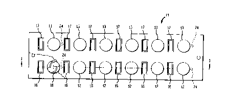
Fig. 1 is a plan view of strip arrangement of dome switches which embody the
principles of the present invention;
I''
,.~
2 1 1 844 1
4a
Fig. 2 is a sectional elevation view along the line I-I of Fig. 1;
Fig. 3 is a partially exploded, sectional elevation view of an enlarged portion of
Fig. 2; and
Fig. 4 is a partially exploded sectional view of a portion corresponding to that of
Fig. 2 illustrating a second embodiment of the invention.
DETAILED DESCRIPTION
In Fig. l there is shown a strip 11 of two banks of dome switches 12,12 and 13,13
as mounted on a circuit board 14, best seen in Fig. 2. It is to be understood that the
configuration of strip 11 is for illustration purposes only, and that any configuration such
as strips, square arrays, or other shapes may readily be used, the actual configuration being
dictated by the circuit board arrangement in the particular functional application. Adjacent
each of the switches 12,12 and 13,13 is a light emitting diode (LED) 16,16 and 17,17 for
providing a suitable indication of the state of each switch and its associated circuitry. In
actual practice, the LED's 16,16 and 17,17 are mounted on the circuit board 14 as part of
the circuitry thereon. At the lower left hand corner of Fig. 1 a portion of the assembly 11
has been broken away to illustrate a switch footprint 18 which is mounted on circuit board
14 and forms part of the circuitry thereon.
With reference to Figs. 2 and 3, it can be seen that the assembly 11 comprises, in
this embodiment, the circuit board 14 of, for example, glass epoxy, upon which the
circuitry, the LED's, 16,16 and 17,17, and the switch footprints 18 are mounted.Overlyingthe circuit board 14 is a first flexible sheet 19 of inert plastic material such
as Mylar~}) or Melinex~ which protects the circuitry on board 14 from cont~min~tion. It
has been found that these materials are impervious to most cont~rnin~nts likely to be
encountered, more particularly, to squalene. As best seen in Fig. 3, sheet 19 has
apertures 21,21 to permit passage of the LED's 16,16, therethrough. It is to be
2118441
understood that LED's 16,16 may be much more compact than is shown in Fig. 3,
being, for example, substantially flat or extending upward from board 14 only a very
short distance, in which case a light pipe could be mounted thereon to transmit the light
upward to the top of assembly 11. On the other hand, LED's 16,16, can be
5 substantially, as shown in Fig. 3, extending upward from board 14 for a considerable
distance. Sheet 19 also has apertures 22,22 thereon to make switch footprints or pads
18,18 accessible to the actuating portions of the switch, as will be discussed
hereinafter. Sheet 19 is also apertured at 23 to permit passage of a locating pin 24, also
to be discussed more fully hereinafter. Board 14 also has apertures 26 therein to
0 receive the locating pin 24.
Overlying sheet 19 is a switch closure sheet 27 of a suitable inert plastic material
such as Mylar, which is also impervious to cont~lnin~nt~. Sheet 27 has apertures 28,28
therein to permit passage of LED's 16,16 or of their associated light pipes, andapertures 29 to permit passage of locating pins 24. On the underside of sheet 27, in
registry with footprints 18,18, are carbon closure pads 31,31, which as will be apparent
hereinafter, close each of the switches by shorting against the footprints 18,18 upon
actuation. The thickness of sheet 19 is sufficient to m~int~in separation between the
footprints 18 and the closure pads 31 to prevent accidental shorting, hence, closure of
the individual switches. In practice, sheet 19 is approximately 0.005 inches thick.
20 Sheet 27, on the other hand, is thin enough to provide sufficient resiliency and
elasticity for closing and opening each switch. In practice, sheet 27 is approximately
0.003 inches thick. Although sheets 19 and 27 are shown as apertured for the LED's in
the case where the LED's are relatively flat, sheets 19 and 27 need not be apertured if
they are transparent, which, in practice, they are. Thus, an additional measure of
25 protection is gained.
A rubber dome sheet 32 of a material such as silicone rubber overlies sheet 27
and has a plurality of actuating buttons 33,33 integrally formed hereon as by molding.
Each button 33 is supported by a thin web 34 which provides the necessary elasticity to
permit the button to be depressed to actuate the switch and, when the pressure by the
30 operator is removed, to spring back to the position shown. ~he underside of each
button 33 has a bearing surface 36 which, when the button is depressed, bears against
the top surface of sheet 27 and forces closure pad 31 down through aperture 22 into
contact with footprint 18, thus closing the switch. As pointed out hereinbefore, when
the actuating pressure is removed, button 33 and pad 31 spring back out of engagement
35 as a result of the elasticity of web 34 and sheet 27. Depending from the underside of
2~18~1
sheet 32 are a plurality of locating pins 24, only one of which is shown, which pass
through the apertures in sheets 19 and 27 and into holes 26 in board 14. Pins 24, which
are preferably, although not necessarily, formed integrally with sheet 32, function to
align and m~int~in the sheets 19, 27 and 32 in proper registry with each other and with
board 14. Sheet 32 also has apertures 35,35 for passage of LED 16 or a light pipe, or
simply for viewing LED 16 from above.
A faceplate 37 overlies sheet 32, and has apertures 38,38 for viewing the LED's
16,16 17,17 and apertures 39,39 to permit buttons 33,33 to project above the surface
thereof. Faceplate may be formed of any of a number of hard, rigid materials such as
o aluminum or plastic, and has whatever graphics or legends are necessary on the face
thereof. Faceplate 37 has, on the underside thereof, threaded holes 41,41, only one of
which is shown, into which are threaded bolts 42,42, only one of which is shown.Each bolt 42 passes through board 14 and sheets 19, 27 and 32 into hole 41 and, when
tightened, pulls the parts into firm contact with each other, as seen in Fig. 2. A spacer
member 43 serves to m~int~in a separation between faceplate 37 and the top of sheet
32 when the assembly is then clamped together. Although the switch assembly is
shown as being clamped together by bolts 42, it is to be understood that other clamping
means might readily be used.
As discussed hereinbefore, the switch of the invention as depicted in Figs. 1, 2and 3, is assembled by overlaying board 14 with sheet 19, sheet 19 with sheet 27, and
sheet 27 with sheet 32, with faceplate 37 overlying, but separated, from sheet 32 and
then by being clamped together. In the event that, for any reason, one of the
components requires replacement, the switch assembly can be readily disassembled,
the faulty part replaced, and the switch reassembled in the field without the necessity of
removing and replacing the entire switch assembly. Thus, from both an operating and
economic standpoint, the switch can, in effect, be repaired with a minimum of down
time and at the cost of a single component as compared to the cost of a replacement
switch.
In Fig. 4 there is shown a second embodiment of the in~1ention. For simplicity
those components of the arrangement of Fig. 4 which are the same as those in thearrangement of Fig. 3 bear the same reference numerals.
In the arrangement shown in Fig. 4, faceplate 37 has depending side walls 46,46,only one of which is shown. Preferably each edge of plate 37 has a sidewall 46
2118~1
depending therefrom which, in the case of a rectangular, square, or other shapedfaceplate, form an open box. Mounted on the underside of faceplate 37, or integral
therewith, are locating pins 47,47, only one of which is shown in Fig. 4. Rubber dome
sheet 32 has apertures 48,48 therein through which pins 47,47 pass in the assembled
5 switch. In the assembly of the switch array and the circuit board 14, the open box is
inverted so that faceplate 37 is at the bottom, and the component layers are then
stacked within the box in proper sequence, commencing with rubber dome sheet 32,then sheet 27 and 19 and circuit board 14, with pins 47,47 passing through the
corresponding apertures in the sheets and into holes 26,26 in circuit board 14. A plate
lo or frame member 49 is then snapped into place against the underside of board 14 and
held in place by suitable means such as springs S 1. It is to be understood that springs
51,51 are only illustrative of any of a number of means for holding member 49 inplace. Member 49 is so dimensioned that, when in place, it forces all of the layers into
firm contact with adjacent layers, thereby insuring proper operation of the switch.
In both of the illustrative embodiments of the invention, disassembly and re-
assembly is both simple and quickly accomplished. Thus, as pointed out hereinbefore,
individual components of the switch can be quickly replaced in the field, and the
reassembled switch will be as cont~ n~tion proof as the original assembly.
The foregoing embodiments of the invention are illustrative of the principles and
features thereof. Numerous modifications may occur to workers in the art withoutdeparture from these principles or from the spirit and scope of the invention.