Note : Les descriptions sont présentées dans la langue officielle dans laquelle elles ont été soumises.
PASTA COOK~R
Background of the Invention
The present invention relates to cooking devices, and
more particularly, devices designed for boiling pasta in a
commercial environment.
Traditionally, the commercial preparation of pasta
involved the boiling of pasta in large pots on a gas stove, or
alternately, the boiling of pasta in large pans on a gas stove, the
pans including apparatus for tilting the pan to pour out its
contents. However, with the advent of high-volume commercial food
establishments which serve pasta, there is need for devices which
are designed exclusively for boiling pasta on a continuous and
high-volume basis.
An initial attempt at developing such a device consisted
of the conversion of a deep fat fryer. With that device, the tank
for holding cooking oil was converted into a water holding tank,
and pasta was placed in baskets positioned within the tank and
cooked while the water in the tank was boiled.
Such converted devices possess inherent disadvantages.
For example, as a result of the continuous cooking of pasta, the
water in the tank quickly became clogged with starch foam, making
it difficult to observe the cooking of the pasta, and increasing
tbe amount of time required for cleaning. Further, the tank drains
tended to become clogged easily with starch foam and pasta
particles, which become extremely sticky when deposited on metal
surfaces, such as the stainless steel of the drain openings.
Accordingly, there is a need for a pasta cooker which is
capable of preparing pasta on a high-volume basis in which the
,.
~118~3
,:
problems of starch foam and drain clogging are minimized.
Summary of the Invention
:''' ~;~
The present invention is a pasta cooker having an open
water tank having a heating mechanism and shaped to receive a
basket of pasta to be cooked, a trough positioned adjacent to the
upper edge of the tank, and a screen box connected to the trough ;~
and tank drains. The trough preferably is coextensive with the ~ -
upper edge of the front wall of the tank and, during cooking of the
pasta, the water level is adjusted such that a small amount of '
water from the upper surface of the tank washes over from the tank
into the trough, carrying with it the starch foam which is
generated by the cooking of pasta Accordingly, during the
continuous cooking of pasta, the starch foam is on the surface of ,~
the wate} in the tank continuously removed from the tank and is '
collected in the trough.
The trough and tank each include a drain which is
connected to the screen box, so that the water and starch foam
collecting in the trough is drained immediately to the screen box,
which is connected to a conventional plumbing drain. The screen '
box includes a removable drawer having perforated side, bottom, and
rear walls, which are positioned within the box to receive the
drain water from the trough and the tank. The screen box drawer -
collects the pasta particles and starch foam entrained in the drain ~; i
water, thereby removing it from the effluent from the trough. ; ;
Consequently, pasta particles and starch foam are removed from all
effluent from the pasta caoker. -';
In a preferred embodiment, the screen box includes a
bottom floor which slopes downwardly and rearwardly to a rearward
opening which is connected to a conventional drain. The drawer is ~ ;~
positioned within the screen box housing such that, in the event ~ .
that the drawer becomes completely clogged with pasta, the water
-2- ~ '
, ;~
...,.
, .. . .
,. ::. i, . :
- ,, .,. ,,'.'
;. ~ ~ '.' ' .~' ~ ~' ~ , ' , ' , '
~ 211~ 3
....
overflowing the drawer simply flows downwardly to the sloping
bottom wall and rearwardly to the drain, thereby minimizing the
likelihood of water overflowing from the screen box.
Also, in a preferred embodiment, the tank for boiling
pasta is ganged with a second tank which lacks a heating mechanism
and is used for chilling and washing the cooked pasta. The second
tank also includes a screen box, which receives water drained from
the second tank. The second tank also includes a spray nozzle on
a flexible hose which is used to spray cold water on the cooked
pasta, as well as for cleaning both the cooking tank and the
washing tank after cooling.
Accordingly, it is an object of the present invention to
provide a pasta cooker having a trough for the continuous removal
of starch foam from the tank during pasta cooking; a pasta cooker
having a filter mechanism such that all effluent water from cooking
is strained to remove starch foam and pasta particles to minimize
the likelihood of drain clogging; a pasta cooker which is capable
of high-volume continuous pasta cooking; a pasta cooker which is
relatively easy to maintain; a pasta cooker in which all of the
major controls for the cooker components are readily accessible to
an operator; and a pasta cooker which is rugged and requires a
minimal amount of maintenance.
Other objects and advantages will be apparent from the
following description, the acc~ ~ying drawings and the appended
claims.
Brief Description of the Drawings
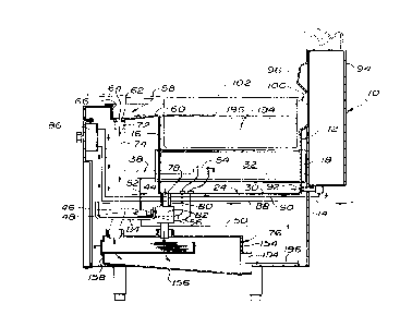
Fig. 1 is a somewhat schematic, side elevation in section
of a preferred embodiment of the present invention, taken at line
1-1 of Fig. 3;
~5
-3-
2 ~ 3
-:
Fig. 2 is a top plan view of the pasta cooker shown in
Fig. l;
Fig. 3 is a front elevation of the pasta cooker shown in
Fig. 1, with portions broken away to reveal interior structure; and
Fig. 4 is an exploded, perspective view of the screen box
of the pasta cooker of Fig. 1.
1 0
Detailed Description
.. ~....
As shown in Fig. 1, the preferred embodiment of the pasta
cooker of the present invention, generally designated 10, includes
an open tank 12 which is supported within a cabinet 14. The tank
12 includes a front wall 16, a rear wall 18 and side walls 20, 22
(see Fig. 2). The tank 12 includes a bottom wall 24 having
downwardly converging surfaces 26, 28 which are connected by a flat
surface 30.
Heat tubes 32, 34, 36, each having an elliptical cross
section, extend between the front wall 16 and rear wall 18, and
receive burner castings 38, 40, 42 of a conventional atmospheric
gas burner system 44. The gas burner system 44 includes a gas
valve 46 which is manually adjustable by knob 48 and directs gas
from feed line 50 to supply lines 52 which are connected to the
burner castings 38-42. A thermostatic sensor 54 is mounted within
the tank 12 on tube 32 and is connected to valve 46 by wire;s 56.
The thermostatic sensor 54 includes a high limit shut off which
closes the valve 46 when the temperature within the tank reaches
225 F, which would indicate that the tank 12 has boiled dry. The
sensor 54 also includes a component which detects temperatures for
set points corresponding to: boil and simmer. Consequently, it is
not necessary for an operator to adjust a gas valve constantly
during cooking to maintain a particular temperature.
-4-
~',,';.".'
.''~ ' ..: ' ":
~ 2 1 ~ 5 3
;-
A trough 58 is positioned adjacent to the tank 12, and,
as shown Fig. 2, is coextensive with the front wall 16. The trough
58 includes a forwardly and downwardly sloping bottom wall 60, a
flat base wall 62 which includes a drain opening 64, a front wall
66 and opposing side walls 68, 70. The drain opening 64 is
connected to a stub tube 72, which, in turn, is connected to a
flexible high temperature hose 74. Hose 74 is connected at a lower
end to a screen box, generally designated 76.
The tank 12 also includes a drain opening 78 which is
formed in the flat surface 30 of the bottom wall 24 and is
connected to a drain tube, generally designated 80. Drain tube 80
includes a drain valve 82 which is actuated by a handle 84 that
extends forwardly to the front of the cabinet, so that it may be
actuated by an operator of the cooker 10. Drain tube 80 also is
connected to drain into screen box 76.
The cabinet 14 supports a fill valve 86 which is
connected to hot water feed line 88 and supplies hot water to the
tank 12 by a hot water fill line 90. Hot water fill line 90 is
connected to a fill opening 92 located at the bottom of the rear
wall 18.
'
The rear of the cabinet 14 includes a support stand 94
25 . having a transverse channel 96 with an opening 98 shaped to receive
~:: the tongue 100 of an open mesh pasta basket 102. Accordingly, the
pasta basket 102 may be suspended from the support stand 94 above
: the tank 12 by inserting the tongue 100 into the opening 98.
In the preferred embodiment of the cooker 10, as best
shown in Figs. 2 and 3, a rinsing tank 104 is supported within the
cabinet 14 adjacent to the tank 12. Rinsing tank 104 is
: substantially identical to tank 12 in construction; however, it
lacks the tubes 32, 34, 36, and associated heating elements of the
gas burner system 34. In the embodiment shown, the rinse tank 104
.
_
4 ;:~ 3 ~ ~
:
also includes a trough 106 having a drain opening 108 that is
connected to a drain tube 110 that drains into a second screen box : -
112. Tank 104 also includes a drain opening 114 which is connected -~
to a valved drain tube 116 that empties into screen box 112. Drain --
tubes 110, 116 and screen box 112 are substantially identical in
construction and components to their counterparts associated to
tank 112.
Cold water fill valve 118 is mounted on the front panel -~
120 of the cabinet 14 adjacent to tank 104, and is supplied by cold - ~ :
water supply line 122. Valve 118 is connected to a fill opening : ~:
124 in tank 104 by cold water fill line 126. - -
~ ~--~:.::
.. . ... ..
The support stand 94 adjacent to tank 104 includes a
sprayer system, generally designated 128. Sprayer system 128 ~ :
includes hot and cold water valves 130, 132, respectively, which in ~ '
turn are connected to hot and cold water supply lines 134, 136. ....
Valves 130, 132 are connected to a flexible sprayer hose 138 which
terminates in a spray nozzle 140. The knobs of the valves 130, 132
and spray nozzle 140 are mounted on an inclined panel 142. . ::
':,,.'.;.'."','''",''
As shown in Fig. 4, the screen box 76 (which is : :
substantially identical in construction to screen box 112) includes j- :~
a housing 144 and a removable drawer 146. The housing 144 includes ~- ~
Z5 a top wall 148, opposing side walls 150, 152, a rear wall 154, a : .. .
bottom wall 156 which is inclined downwardly and rearwardly, and a .' ::;
front wall 158. Side wall 150 includes an L-shaped channel 160 ::. :
which is attached to a tubular channel 162 (see Fig. 3) that is :.. ~
integral with the cabinet 14. The top wall 148 includes nipples ~. , :~;
164, 166 which receive the drain hose 74 from the trough 58 and the
drain tube 80 from the tank 12. The connections are sufficiently
more to provide a vacuum break. Side walls 150, 152 include drawer .
slides 168, 170. Front wall 158 includes a rectangular opening 172 .~
which is shaped to receive the drawer 146. .: .
-6-
.~, ' ~ ..
~ 211~1a3
Drawer 146 includes an imperforate front face 174 which
includes a pair of opposinq side flanges 176, 178, and a handle
180. Drawer 146 also includes side walls 182, 184, a bottom wall
186, and rear wall 188. Walls 18~-188 preferably are made of
stainless steel which is perforated such that it is a minimum of
60% open.
.:
The front face 174 and side flanges 176-178 are shaped
such that the side flanges overlies the side walls 150, 152 of the
housing 144 when the drawer is inserted therein. The side walls
150, 152 also include overcenter buckles 190, 192 (see Fig. 2)
which engage lugs 194 carried on the side flanges 176, 178 (only
one lug 194 being shown in Fig. 4, it being understood that flange
178 carries an identical lug). Overcenter buckles 190, 192 operate
to positively mechanically secure the drawer 146 to the housing 144
during operation.
: : '
The drawer 146 is positioned directly beneath the nipp~es
164, 166 so that drain effluent from the trough 58 and tank 12
flows directly into the drawer 146 and the perforated 182-lB6
filter any particulates carried out of the drain water. The rear
wall 154 includes a drain opening 194 which is connected to a
conventional drain line 196 (see Fig. 1).
The operation of the pasta cooker 10 is as follows.
Initially, the operator actuates fill valve 86 which permits hot
water to flow through lines 88, 90 through the fill opening 92 to
fill tank 12 with hot water. When tank 12 becomes suffici!ently
fillled, the gas burner system 34 is actuated, and burners 38, 40,
42 are ignited to begin heating the water 194 (see Fig. 1) in tank
12. The control knob 48 is set for boil, and the water is heated.
When the water 194 begins boiling, the basket 102, filled with
uncooked--or partially cooked-- pasta is placed in the tank 12 and
rests upon the tubes 32, 34, 36 within the tank.
' ,' ';
.. , :. :
. .
: '~118~ a3
As the pasta cooks, the upper surface 196 of the water
194 beqins to foam with starch. This starch foam begins washing
from the tank 12 into trough 58, wherein it flows down bottom wall
60 to base wall 62. After a period of boiling, it is preferable to
actuate the fill valve to provide a constant inflow of hot water
through opening 92, which causes a small amount of water 194 to
continually flow from tank 12 to trough 58. Since the starch foam
floats on the upper surface 196 of the water 194, the starch foam
is continually removed from the water in the tank. Once in the
trough 58, the water and foam flows through the drain opening 64,
drain tube 74, and into the screen box 76.
Once the water has flowed into screen box 76, it flows
through the drawer 146 and the perforated walls 182-188 of the
drawer filter out and retain the foam and any pasta particles
entrained in the water. The remaining water flows through walls
182-188 and is conveyed rearwardly along the housing 144 by flowing
downwardly and rearwardly inclined bottom wall 156 to the drain
opening 194, at which time the drain water enters the conventional
drain pipe and is conveyed to a sanitary sewer system.
Once the pasta in basket 102 has been sufficiently
cooked, the basket 102 is lifted from tank 12 and may be suspended
on channel 196, in the manner previously described to allow water
to drain from it. The basket 102 is then placed in tank 104, which
may be filled with cold water by means of valve 118 and water
supply lines 122, 126. Alternately, or in addition, the pasta can
be chilled by spraying it with water from spray nozzle 140, in
which case the valves 130, 132 are adjusted so that the spray
nozzle dispenses cold water.
:-, :''
After the cooking period has been completed, valve 82 is
actuated to drain the tank 12 of water. The drain water travels
through drain tube 80 and into screen box 76 through nipple 166.
Drain water from tank 12 flows through the perforated walls 182-186
-8-
, ~',:,:,,
'~ ' ,. '.
- : .
3 ::
of drawer 146 and the particles of pasta, any other large
contaminants, and any foam in such water is contained within drawer
146; the filtered water then flows along bottom wall 156 and out
drain opening 194.
When the draining procedure for tank 12 has been
completed, drawer 146 may be removed and cleaned, preferably by
scraping material from the perforated walls 182-188 into a waste
container. It is also preferable to perform such a drawer 146
cleaning procedure intermittently during the cooking procedure, in
which case it is preferable to have at least two drawers 146 so
that they may be alternated to provide continuous filtering of
drain water.
Similarly, after the cooking procedure has been
completed, tank 104 is drained by actuating the valve on drain line
116 and draining the cold water through screen box 112, where a
filtering and draining process occurs which is substantially
identical to that for screen box 76. Once both tanks 12, 104 have
been drained, the tanks can be cleaned by spraying them with water
from spray nozzle 140. The temperature of such cleaning water may
be adjusted appropriately by valves 130, 132.
It is also within the scope of the present invention to
provide an array or battery of tanks, each being constructed as
either tank 12 or 104, to ac~- -date high-volume preparation of
pasta. For example, it is within the scope of the invention to
provide two tanks 12, positioned on either side of a tank 104, so
thatlthe single tank 104 could provide a draining and chilling
function for pasta being cooked in each of the tanks 12. Such an
arrangement is shown in phantom in ~ig. 2 wherein a second tank 12'
is positioned opposite tank 104 from tank 12.
While the forms of apparatus herein described constitute
preferred embodiments of this invention, it is to be understood
' ,;
-- , .
---' 2118~
that the invention is not limited to these precise forms of -
apparatus, and that changes may be made therein without departing
from the scope of the invention.
What is claimed is: - -
,
";. '
" '. '.,'-.'
.... .
". '' ',,:
'~'~,'- ,. " -
.. .... ..
'
;..~ - ... ....
~; ,, .-~. .
. .
. /;. ~
. .: . ...
, , . ., ,:~. ,.
,.: .., . ~ . .,
. : ~ : , .:
--10--
. ' ,: ,; ' ,; ' ,': ~ , ,
,',,, ~ ' . ' . ' . . ,;. '' . ,:. . ,';' ' ', , ,' , ', ~ ' .' . ' ,