Note : Les descriptions sont présentées dans la langue officielle dans laquelle elles ont été soumises.
CA 02118787 1997-12-03
TODD.P0006
FLEXIBLE RETRACTABLE DOOR
Scope of the Invention
This invention relates to a flexible retractable
5 assembly useful for a variety of purposes including
various types of doors, space dividers, coverings and
the like. Typical uses comprise entryway doors, cabinet
doors, furniture doors, doors for enclosing bathtubs and
showers and for closing closets and the like, various
10 covers, and screens as used, for example, to cover an
entrance from a patio to a home interior, window
screens, and screen doors and windows for a lanai.
Background to the Invention
Doors, bug screens, and other coverings of the type
referred to are well known for many purposes. The
various assemblies described herein are intended as
substitutes for such conventional products.
In the context of doors for use in water
20 containment applications such as about bathtubs and
showers, known doors suffer a number of disadvantages.
Rigid panel glass and/or plastic doors are known
specifically adapted as tub and shower doors. Such
doors have rigid fixed panels of glass or plastic opened
25 by sliding or by being hinged typically either as a
single hinged panel door or as a bi-fold door. Known
rigid panel doors suffer the disadvantages that when
hinged, they require space for the doors to swing or,
when sliding, they do not permit full access to the tub
30 or shower. When not open, the doors have the
disadvantages of taking up a considerable amount of
space.
Other door-like closures for water containment
applications are well known as in the form of flexible
35 slidable shower curtains hung from a bar above the
tub/shower opening. While inexpensive, such curtains
are frequently ineffective to prevent water leakage and
considerable water damage can result especially through
careless use as may frequently occur in hotels and the
CA 02118787 1997-12-03
like. Attempts have also been made to use plastic
sheets which can be pulled out to cover the shower
opening and then rewound or refolded to conserve space
when not in use. Such attempts have also not been
5 successful from the standpoints of utility, cost and
aesthetics.
In the context of doors for use in non-water
containment, uses such as entryway doors, doors to close
closets, cabinets and the like, many doors are known
10 which are in effect, retractable. These include,
notably, bi-fold doors and accordion doors. Both of
these types of doors have the disadvantage that when
retracted, they still impair entry to the opening and
occupy a considerable amount of space. Typically, these
15 doors are of a relatively substantial construction and,
therefore, can be relatively expensive.
Hinged doors and sliding panel doors are also well
known as having various disadvantages in that they
interfere with otherwise usable space and/or limit the
20 percentage of available access to the closet or other
area being enclosed.
Current designs for screen doors, screen windows
and room dividers also present problems since solid
sliding doors, as well as solid frames for screens,
25 occupy considerable space when not in use. Either they
must be removed when not in use, or moved into wall
openings for storage which is expensive and space
consuming or they must remain visible which is
unsightly.
Summary of the Invention
Accordingly, to at least partially overcome the
disadvantages of previously known devices, the present
invention provides a flexible retractable assembly for
35 use as a door, space divider, bug screen or other
covering in a variety of applications. The assembly
generally embodies a flexible sheet having a permanent
CA 02118787 1997-12-03
or substantially permanent memory set as a coil to roll
up on itself automatically as a spiral coil. The
flexible retractable assembly in accordance with the
invention provides an improved substitute for known
5 doors in a large variety of applications as explained in
the foregoing background section of this application.
It is an object of the present invention to provide
a flexible retractable assembly for use in a wide
variety of applications such as a door assembly for
10 water-retaining bathtubs, and/or showers, for entryway
doors, closet doors, room dividers, cabinet doors,
screen doors and windows, and various covers such as a
florescent light cover, all such assemblies having a
simplified construction which may be easily and
15 efficiently manufactured.
Another object is to provide new and improved
assemblies which are of a durable and reliable
construction and which may be efficiently and reliably
assembled.
Another object is to provide flexible retractable
assemblies which are simpler, lighter, easier to install
or assemble than wood or glass doors, which are
adaptable to non-linear and free form applications, and
which provide substantially greater access to the
25 opening to be closed.
In general respects, the present invention provides
a flexible retractable assembly comprising:
a flexible sheet having front and rear end edges
and laterally extending side edges,
said sheet having a permanent memory set to roll up
on itself or otherwise form a compact configuration
automatically, for example, as a spiral coil around an
axis proximate said rear edge or as an accordion
configuration,
locating means retaining said coil or other
configuration at one side of an opening,
guide means guiding said sheet from the locating
CA 02118787 1997-12-03
means across the opening,
wherein by the sheet moving from the locating
means, the sheet is movable between:
(a) a retracted position with the front end edge
5 near the locating means and the substantial entirety of
the sheet in a compact state, and
(b) one or more extended positions with the front
end edge spaced from the locating means and a
substantial portion of the sheet extending at least
10 partially across the opening.
These general characteristics of the assembly are
utilized for each of the various applications of the
invention by combining certain additional features to
achieve specific functions. Thus, the sheet may be
15 employed as a door for a shower and means are then
provided to avoid splashing of water outside the shower
area. In the case of a closet door, a tambour
arrangement or other stiffening means may be added to
improve the aesthetics and/or to provide a more sturdy
20 construction. A screen door or window function may be
achieved by utilizing a self-retracting sheet with
openings for the passage of air. The accompanying
drawings and description thereof set forth these and
other such features which all form part of the inventive
25 subject matter.
Brief Description of the Drawings
Figure 1 is a perspective view of a bathtub shower
flexible retractable door assembly comprising a first
30 embodiment of the present invention showing the assembly
operatively mounted on a bathtub;
Figure 2 is a cross-sectional plan view along line
2-2' in Figure 1;
Figures 3 and 4 are cross-sectional plan views
35 along line 3-3' of Figure 1 showing the door assembly in
retracted and extended positions, respectively;
Figure 5 is a partial cross-sectional view along
CA 02118787 1997-12-03
line 5-5' of Figure 1;
Figure 6 is a schematic partially cross-sectional
and partially exploded view of a second embodiment of
the invention similar to the first embodiment in many
5 respects;
Figure 7 is a partial, exploded perspective view of
a third embodiment of the present invention having
features in common with the first and second
embodiments;
Figure 8 is a perspective view of a neo-angle
shower door assembly comprising a fourth embodiment of
the present invention showing the assembly mounted about
a shower stall;
Figure 9 is a schematic, partially cut-away rear
15 elevation view of a fifth embodiment of the present
nventlon;
Figure 10 is a cross-sectional elevational view
along line X-X' in Figure 9;
Figure 11 shows a schematic partially cut-away
20 pictorial view of a flexible retractable door in
accordance with the present invention received in a
guide channel;
Figure 12 is a schematic drawing showing a
flexible, retractable door in accordance with the
25 present invention in a fully unwound condition;
Figure 13 is a schematic view of a variation of the
invention applied to a shower door or the like;
Figure 13A is a schematic view of a cord and pulley
system used with the door of Figure 13;
Figure 13B is a detail view of the adjustable upper
end of the rod used for supporting the coiled sheet of
Figure 13;
Figure 14 is a schematic view of a variation of the
invention illustrating the application of the concepts
35 of Figure 12 to a neo-angle shower door;
Figure 15 is a schematic view of a variation of the
invention applied to a cabinet door or the like with the
CA 02118787 1997-12-03
door in the open position;
Figure 16 is a schematic view of the door of Figure
15 shown in the closed position;
Figure 17 is a schematic view of a variation of the
5 invention applied to a closet door or the like;
Figure 17A is a detail view of the door of Figure
17 including a motor drive feature;
Figure 18 is a schematic view of a variation of the
invention applied to a double closet door configuration;
Figure 18A is an enlarged fragmentary view of a
latch means usable with the embodiment of Figure 18;
Figure 19 is a schematic view of a variation of the
invention applied to a fluorescent light cover;
Figure l9A is an enlarged fragmentary sectional
15 view illustrating a variation of the embodiment of
Figure 19;
Figure 20 is a schematic view of a variation of the
invention applied to a screen door;
Figure 21 is an enlarged fragmentary view of a
20 portion of screen of the type used in the embodiment of
Figure 20 taken about the line 21-21 of Figure 20;
Figure 22 is a schematic view of a variation of the
invention applied to a screen configuration used in
conjunction with a hinged closure;
Figure 23 is a front elevational view of a
variation of the invention applied to a sliding door
shown in the closed position;
Figure 24 is a front elevational view of the
sliding door of Figure 23 in the partially-opened
30 position;
Figure 25 is a rear elevational view of the door of
Figure 23 in the fully-opened position;
Figure 25A is a fragmentary detail view of a
control arrangement for pivoting arms used in
35 conjunction with the embodiment of Figures 23-25;
Figure 25B is a vertical sectional view
illustrating an application involving a double side
CA 02118787 1997-12-03
sheet configuration;
Figure 26 is a perspective view of a variation of
the invention applied to an entertainment center;
Figure 27 is a view of the center of Figure 26 with
5 the upper section in the fully-opened position;
Figure 28 is a view of the center of Figure 27 with
the lower section in the partially opened position;
Figure 29 is a schematic view of a sheet having
partial memory set and areas without memory set;
Figure 30 is a perspective view of a trolley
mechanism for top support of the lead edge of a sheet;
Figure 31 is a perspective view of a sheet having a
turned-in edge for edge curl control;
Figure 32 is a front elevational view of a
15 variation of the invention applied to a closure with
multiple top edge support;
Figure 33 is an enlarged fragmentary cross-
sectional view of the top edge support mechanism shown
in Figure 32;
Figure 33A comprises a schematic illustration of a
collector raceway usable with the top edge support of
Figure 32;
Figure 34 is a schematic fragmentary perspective
view of a coiled sheet characterized by a "watch spring"
25 memory set;
Figure 35 is a schematic fragmentary perspective
view of a sheet with the watch spring memory set
combined with a spacer;
Figure 36 is a front elevational view of a
30 variation of the invention which includes a sheet with
"accordion" memory;
Figure 37 is an end view of the top support track
for the accordion-type sheet of Figure 36;
Figure 38 is a top end view of the box enclosure
35 for the sheet of Figure 36;
Figure 39 is a perspective view of a variation of
the invention using a double coil sheet configuration;
CA 02118787 1997-12-03
Figure 40 is a perspective view of a variation of
the invention using an alternative form of double coil
sheet;
Figure 41 is a perspective view of a sheet
5 variation which is provided with individual flat
segments for attachment of a tambour or the like;
Figure 41A schematically illustrates a method for
achieving the flat segments in the sheet shown in Figure
41;
Figure 42 is a plan view of a sheet with memory
partially covering a tambour arrangement; and,
Figure 43 is a plan view of an alternative form of
sheet with memory partially covering a tambour
arrangement.
Detailed Description of Preferred Embodiments
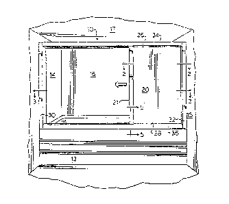
Reference is made first to Figure 1 which shows as
a first embodiment of the invention, a shower door
assembly generally indicated 10 positioned to open and
20 close the access opening to a bathtub 12, otherwise
enclosed by side walls 14 and 15, end wall 16 and
ceiling 17. The door assembly 10 is shown to comprise a
rectangular frame and a door. The door comprises a
rigid handlebar 21 and a rectangular sheet 20. As seen
25 in Figures 1 and 2, sheet 20 has a front edge 22, a rear
edge 24 parallel the front edge, and parallel upper and
lower side edges 26 and 28. The frame has left side
frame member 30, right side frame-and-coil locating
member 32, upper frame and guide channel forming member
30 34 and lower frame and guide channel forming member 26.
The upper and lower members 34 and 36 are formed
with channels to receive and guide the upper and lower
side edges 26 and 28, respectively, of the sheet 20
across the opening of the tub from the locating member
35 32. This is best illustrated in Figure 5 with reference
to the lower channel forming member 36 having an
elongate channel 38 to receive therein lower edge 28 of
CA 02118787 1997-12-03
the sheet.
Sheet 20 comprises a sheet of material having a
permanent or substantially permanent memory set so as to
roll up upon itself automatically as a spiral coil 42
5 about its axis indicated 40. The nature and memory of
the sheet 20 is described later in more detail.
Coil locating member 32 is shown as an elongate
hollow tubular member of generally rectangular
configuration having a vertical slot 44 therethrough
10 through which the sheet passes from the coil 42 and into
the channels in the upper and lower frame members which
guide the sheet across the opening of the tub enclosure.
In use, on a person manually pulling or pushing
handlebar 21, the door is movable between the retracted
(open) position shown in Figure 3 and the extended
(closed) position shown in Figure 4. In movement
between positions, the coil 42 rotates about its axis
40. In the retracted position, the handlebar 21 to
which the front edge 22 of the sheet is secured is near
20 the coil 42 and the substantial entirety of the sheet is
coiled about axis 40 so as to form the coil 42. In the
extended position, as seen in Figure 4, front edge 22
carried by handlebar 21 is spaced from the coil 42 which
remains inside frame member 32 and a substantial portion
25 of sheet 20 is uncoiled and extends across the opening
of the tub with its upper and lower edges received in
the channels of the upper and lower frame members. In
the retracted position as seen in Figure 3, the
substantial majority of the enclosure is open for
30 access.
Sheet 20 rolls up upon itself into a spiral coil 42
about its axis 40. It is to be appreciated that the
axis 40 may not be precisely located and thus may be
considered to be imaginary. The axis 40 may, for
35 example, represent the general center of the coil 42
about which the coil exists. Embodiments may be
configured to permit the axis or center of the coil to
CA 02118787 1997-12-03
- 10 -
be movable.
Sheet 20 is preferably of a resiliently flexible
material, such as the polyester film of E.I. du Pont de
Nemours and Co. (Inc.) known by the trade mark Mylar,
5 which is capable of being prestressed with a substantial
permanent curvature of a small radius and relatively
long duration memory. The sheet material of sheet 20 is
prestressed to have a permanent or substantially
permanent memory set in any predetermined shape and,
10 more particularly, to roll up on itself automatically
forming a spiral coil 42 around axis 40 proximate the
rear end edge 24. The coil has a memory such that it
will return to its tight coiled form even though
repeatedly unrolled or left unrolled for relatively
15 long periods of time. While the sheet material is
preferably polyester film, other films may be used which
are capable of being prestressed to have this permanent
coil set and memory. The sheet 20 may comprise a sheet
material of one of the types disclosed in U.S. Patent
20 3,241,899 to Donker, USP 3,542,445 to Donker or
generally referred to in USP 2,852,143 or USP 3,195,616
of Taber. A preferred form of the sheet comprises Mylar
with a nominal dimension of 0.01 inches in thickness or
greater, such sheets measuring, for example, in the
25 order of 0.007 inches in thickness. A preferred range
is 0.007 to 0.02 inches although thicker or thinner
sheets may be used.
Sheet material 20 has an inherent memory, whereby,
when unrolled, it tends to recoil itself in the form of
30 the coil 42. On movement from the retracted open
position of Figure 3 to an extended closed position of
Figure 4, forces are manually applied to the roll so as
to unroll it. On release of these forces, in the
absence of friction, sheet 20 would tend to assume its
35 memory position and thereby reform the coil within frame
member 32. To permit the sheet 20 to remain retracted
to a fully retracted position or at any selected
CA 02118787 1997-12-03
position intermediate the full retracted and fully
extended positions, it is preferred that there is a
mechanism for retaining the handlebar 21 at any position
between the fully extended and fully retracted position
5 when it is released. In the first embodiment, this is
provided, at least in part, by friction between the
sheet 20 or handlebar 21, and, the upper or lower frame
members 34 and 36.
While not clearly shown in Figure 2, coil 42 rests
10 upon a support surface generally indicated 46 by contact
between supporting surface 46 and lower side edges 28 of
the sheet. As schematically illustrated in Figure 5,
support surface 46 is disposed in the same horizontal
plane as the lowermost surface of the channel 38.
15 Support surface 46 is provided to have a low friction so
as to facilitate uncoiling and sliding of the side edges
of the coil thereon. This is advantageous to facilitate
unwinding of the coil and its return to a retracted,
coiled position.
In the first embodiment, locating member 32 is
disposed circumferentially about coil 42. While shown
rectangular, other configurations would be suitable.
Member 32 has a forward face 48 in the plane of the
bathtub opening and a side face 50 directed towards the
25 opening. As seen vertical slot 44 is preferably offset
from the center of the side face 50 so as to be located
in side face 50 proximate forward face 48 and in
alignment with the channels in the upper and lower frame
members 34 and 36. Offsetting the vertical slot 44 in
30 the locating member 32 provides for enhanced guiding and
locating of the coil 42 within the member 32 as by
contact of the outer surfaces of the coil with inner
surfaces of the locating member 32. Slot 44 may be
offset to either the forward face or rear face of member
35 32, depending on whether the coil is coiled clockwise or
counterclockwise as seen above.
Reference is now made to Figure 6 and 7 showing
CA 02118787 1997-12-03
second and third embodiments which are similar to the
first embodiment differing principally in the manner in
which the roll is located. In all the figures, similar
reference numerals are used to indicate similar
5 elements.
Referring to Figure 6, this assembly is identical
to that shown in Figures 1 to 5 with the exception that
in addition to the coil being located by being received
within locating member 32, preferably identical, part-
10 axle members or centering posts 52 and 54 are insertedinto the upper and lower open ends of coil 42. Each
centering post 52 and 54 has a stub axle 56, a radially
outwardly extending flange 58 and a cylindrical
centering button 60. With the stub axle 56 inserted
15 inside coil 42, one surface of flange 58, for example,
upper surface 46 of flange 58 of lower centering post 54
is in contact with the lower side edge of the sheet 20.
Lower centering post 54 is journalled within member 32
for rotation about axis 40 and with its upper surface 46
20 located at a suitable height as, for example, indicated
in Figure 5 with respect to the first embodiment. By
reason of centering post 54 being journalled for
rotation, this assists in permitting the sheet 20 to
coil and uncoil in extending and retracting of the door.
The embodiment of Figure 6 is preferred in that
centering posts 52 and 54 are not fixed to the sheet 20
but rather, for easier assembly, manufacture and
replacement, merely rest within the center of the coil.
Reference is now made to Figure 7 which shows an
30 exploded view of a third embodiment in accordance with
the present invention.
In Figure 7, locating member 32 is shown in dotted
lines to indicate it is optional. Upper and lower
locating end plates 66 and 68 are provided each having a
35 centering aperture 64 to receive the centering buttons
60 of a unitary axle member 62 which is rotatably
journalled for rotation about axis 40. Axle member 62
CA 02118787 1997-12-03
has flanges 58 of which the lower flange 58 has an upper
supporting surface 46 to support and engage the lower
side edge 28 of the sheet 20. The axle member 62, by
itself, can locate the roll 42 adjacent one side of the
5 bathtub enclosure without the need for locating member
32 of the first and second embodiments. Locating member
32 may alternately be provided as indicated, for
example, in dotted lines in Figure 7.
In the context of Figure 7, it is also preferred
10 that sheet 20 is not fixed to the axle member 62,
however, in certain circumstances it may be advantageous
to secure the rear end 24 of sheet 20 to axle member 62.
While Figure 7 is the only figure which shows the
locating member 32 is optional, it is to be appreciated
15 that locating member 32 could be eliminated in other
embodiments, for example, in the embodiment of Figure 6.
While the first three embodiments show different
configurations for locating the coil 42 adjacent one
side of the tub closure, many other hybrid
20 configurations are apparent. For example, the
embodiment of Figure 7 could be modified to as to merely
provide short part-axle members similar to centering
posts 56 which extend upwardly and downwardly a short
distance from each of the holes 64 in the plates 66 and
68 in Figure 7. These centering posts 56 could be fixed
in the hole 64 without rotation. With frame member 32
removed, a simple and pleasing configuration would
appear with the roll being permanently seen as a tubular
column at the side of the tub. This would be
30 particularly so if, when in a fully retracted position
as shown in Figure 3, a sufficient quantity of the roll
remains uncoiled so as to at all times give the
appearance of a cylinder.
All of the first three embodiment8 are illustrated
35 as having the same handlebar 21 and configuration of the
upper and lower frame 34 and 36.
Lower frame member 36 may be extruded from suitable
CA 02118787 1997-12-03
- 14 -
materials such as plastics or metal including aluminum
with channel 38 provided therein. The lower member 36
is secured to the upper outer edge of the bathtub 12 so
as to form a water impermeable seal therewith and
5 therefore retain water within the enclosure when the
door is closed. The illustrated extruded member 36 has a
pleasing, exemplary rounded upper surface with the lower
surface of the handle bar 21 similarly configured. A
low friction sliding pad 70 is secured to the lower
10 surface to the lower surface of the handlebar 21 to
permit the handlebar to readily be slid on the frame
member 36. While many shapes and profiles are suitable
for the extruded member 36 and for the handlebar 21, the
illustrated curvature of the bottom of the handlebar and
15 frame member 36 is one configuration which assists in
providing accurate location of the handlebar 21 above
the lower frame 61.
In addition to the domed upper wall 72 of the frame
member 36, an internal bevelled rib 74 is provided
20 within member 36 and this serves to permit water which
may accumulate within channel 38 to pass via an opening
76 internally into the channel and then into the tub
enclosure via spaced openings 78 as indicated by the
arrows in Figure 5.
Figures 6 and 7 show the upper frame member 34 as
comprising an extruded member which is secured
horizontally across the tub enclosure supported as, for
example, shown in Figure 1 by being secured to the walls
14 and 16 about the tub enclosure preferably via side
30 frame member 30 and any locating member 32. Upper frame
34 has an upwardly extending channel 80 to engage the
upper side edge 26 of sheet 20 and guide the same across
the tub enclosure.
The first three embodiments illustrated in the
35 drawings all show a preferred system for maintaining the
front edge 22 of the sheet 20 oriented parallel the axis
40 about which the coil unwinds so as to assist in
CA 02118787 1997-12-03
maintaining the door in vertical alignment in the plane
of the opening as is advantageous for smooth rolling and
unrolling of the door with the sheet to slide smoothly
within the channels of the upper and lower frame
5 members. Vertical alignment is also preferred from an
aesthetic view, that is, in appearance. Figure 6 thus
shows rigid upper and lower plate members 82 and 84 each
having an L-shaped configuration and secured both to the
upper and lower front corners of the sheet 20 and the
10 handlebar 21. These plates 82 and 84 extend into the
channel 38 of the lower frame member 36 and the channel
80 of the upper frame member 34. Channels 38 and 80 are
provided of sufficient width to permit sliding of the
combined plate 82 and 84 and sheet 20 as best seen in
15 Figure 5. The rigidity provided by rigid plates 82 and
84 assists in preventing bending of the sheet 20 about
its front edge 22 as may particularly increase the
friction or force required to slide the sheet within the
upper and lower frame members.
Rigid plates 82 and 84 are fixedly secured to
handlebar 21 and together they assist in ensuring the
sheet 20 is maintained square with its front edge
vertical. In this regard, Figure 6 shows in exaggerated
form the plate 82 extending rearwardly from the front
25 edge 22 of the sheet 20. With the plates 82 and 84
spaced a vertical distance such that their upper and
lower surfaces closely engage the end surfaces of the
respective channels 80 and 38, such engagement serves to
maintain handlebar 21 square vertically between the
30 upper and lower frame members thus ensuring the front
edge 22 of the sheet is maintained vertical. In the
embodiment of Figure 6, to the extent the plates 82 and
84 extend rearwardly from the front edge 22 of the
sheet, this will impair the ability of the door to fully
35 retract into locating member 32. It is, therefore,
preferred that the rigid plate 82 be or reduced length
and extend either only the width of the handlebar 21 or
CA 02ll8787 l997-l2-03
- 16 -
extend forwardly from the handlebar 21. Many other
configurations may be provided for maintaining the
handlebar and front edge 22 square to the frame member
12, for example, including spaced wheels or other slide
5 members to engage and contact surfaces in complimentary
upper and lower frame members. Plates 82 and 84 by
reason of being relatively closely received between the
sides of the channels also serve to prevent twisting of
the handlebar 21.
It is to be appreciated that the handlebar 21 and
plates 82 and 84 of the preferred embodiments are not
necessary and that by selection of the sheet 20 to have
sufficient inherent stiffness that these bars and plates
could be eliminated in their totality. It is preferred
15 that some handle be provided even if it may be in the
form of a simple plastic or metal strip possibly only
marginally wider than the sheet 20 and coupled to extend
vertically along the forward edge 22. Such a bar may or
may not be received within the channels in the upper and
20 lower frame members.
The embodiments show the sheet material as
comprising a unitary sheet. The sheet may, however,
comprise a composite of Mylar and other materials. For
example, other sheet material may be attached, bonded or
25 laminated to a Mylar sheet to improve decorative
appearance or mildew control. In addition, the Mylar
could have bactericidal or antimycotic compounds
incorporated directly therein. The bonding or
lamination of Mylar or other material as may be suitable
30 to provide a more substantial door and, particularly,
one which may have increased rigidity in a vertical
direction against bending rather than as is necessary
for coiling. For example, a material having
corrugations which extend vertically could be coupled or
35 laminated to the Mylar sheet 20 or other vertically
extending reinforcing devices could be provided at
spaced locations coupled to the Mylar. It is generally
CA 02118787 1997-12-03
preferred, however, that sheet 20 comprise merely a
single sheet of Mylar material having sufficient
thickness to provide sufficient vertical rigidity such
that the sheet 20 will not bend vertically so as to
5 reduce its overall height and permit its upper side edge
to become disengaged from the upper channel 80. Use of
the unlaminated Mylar material is most economical.
The door assembly preferably is to be configured
such that frictional force arising in moving the curtain
10 between the retracted and extended positions is
minimized. However, the assembly should preferably be
configured such that the curtain will maintain any
position between the retracted and extended positions in
which it is placed. The Mylar sheet, if formed so that
15 the entirety of the sheet will form in the shape of a
coil, will have a tendency for the front end edge of the
roll to coil itself. This coiling of the forward edge
can be utilized so as to permit this front edge, when
not manually moved, to coil into friction engagement
20 within the channels of the frame member and, thus, act
as a stop. To the extent this may be desired, when
prestressing the sheet 20 to have a desired
configuration, a separate "memory" can be applied to the
front edge of the sheet 20 so as to provide an increased
25 or decreased coiling and achieve a desired stopping
power.
An alternative retaining system would be to provide
a magnetic strip along one or both of the upper and
lower channels 38 and 80 and an interacting
30 ferromagnetic material strip near the upper front
corners of the sheet. Such low strength magnetic strips
could be provided so as to permit sliding of the sheet
material between the retracted and extended positions
yet when released, retain the door against closing under
35 the memory forces of the coil. Providing the
ferromagnetic strip near the front edge of sheet 20 may
be advantageous to use in combination with the magnetic
CA 02ll8787 l997-l2-03
- 18 -
forces and the inherent tendency of the leading front
edge to recoil. It will be understood, of course, that
a magnetized strip may be applied to either the sheet or
the channels, and the ferromagnetic material then used
5 on the other surface.
The illustrated embodiments show a frame including
both upper and lower frame members 34 and 36. It is to
be appreciated that only one of the upper and lower
frame members may be necessary particularly insofar as
10 the handlebar 21 may be provided and the one of the
upper frame member or lower frame member may
sufficiently guide the sheet to maintain it in a desired
configuration. For example, a more elaborate carriage
could be provided to be engaged by only one of the upper
15 and lower members.
The preferred embodiments should provide relatively
substantial upper and lower frame members. It is to be
appreciated that in a simplified form these frame
members could comprise relatively small and simple
20 extrusions which would be extremely economical. As
well, a simple extrusion may be provided so as to be
secured to the tub enclosure in a curved configuration
as may be advantageous to have the door follow the
outline of an oval or curved tub or other enclosure.
Flexible retractable doors in accordance with the
present invention may readily be adapted to be sold as a
kit ready-to-install, for example, as a bath enclosure,
a shower enclosure or a closet enclosure. The kit could
include all necessary elements, including all necessary
30 framing and hardware.
Reference is now made to Figure 8 which shows as a
fourth embodiment of the invention, a shower door
assembly generally indicated 10 positioned to open and
close the access opening of a neo-angle shower otherwise
35 enclosed by side walls 14 and 15.
The door assembly shown in Figure 8 iS
substantially identical to that shown in Figure 1 with
CA 02ll8787 l997-l2-03
- 19 -
the exception that the upper and lower frame and guide
channel forming members 34 and 36 have sections which
are curved. The flexible extendable door assembly in
the present invention is to be appreciated to readily be
5 adapted to extend in upper or lower frame and guide
channel forming members which have curved and/or
straight sections. In the embodiment of Figure 8, it is
preferred but not necessary that the curvature of the
sheet 20 when extended across the shower be in the same
10 direction as the coil 42 tends to wind upon itself.
Reference is now made to Figures 9 and 10 which
show a fifth embodiment of a tub or shower door assembly
similar in most respects to that of the first
embodiment. Figure 9 shows the assembly as seen from the
15 rear, inside of the shower. The distinctions
illustrated in Figure 9 include firstly, a track and
wheel system for guiding the handlebar 21 and, secondly,
a separate draw system for reducing the forces required
to move the coil towards the extended position.
In Figure 9, the handlebar 21 carries at each end a
pair of guide wheels indicated 100 which are adapted to
roll in a guideway 102 provided in each of the upper and
lower frame and guide channels forming members 34 and
36. This may be best seen in Figure 10 with the
25 guideway 102 disposed in this embodiment above the
elongated channel 80 of upper channel forming member 34
which receives and guides handlebar 21 and the upper end
of sheet 20. While Figure 10 merely shows the upper
frame and guide channel forming member 34, the lower
30 frame and guide forming channel member 36 will have a
similar configuration. Figure 10 shows but one
configuration of the guideway and wheels and many other
configurations and arrangements of guides and single or
multiple wheels or sliders are known to persons skilled
35 in the art.
In Figure 9, as in Figure 1, the frame-and-coil
locating member 32 locates the spiral coil 42 of the
CA 02ll8787 l997-l2-03
- 20 -
sheet which is extendable towards the left as seen in
the rear view of Figure 9.
Figure 9 also shows a drawing system for assisting
in reducing the forces necessary to draw the sheet 20 to
the extended position. This drawing system includes a
vertically disposed journalled axle member 104 which
carries a spool 106 near either and a coil spring 108
proximate its center. Thin wires 110 and 112 are
coupled at a first end 114 of each to the handlebar 21
10 and at their second end 118 to their respective spool
106. The axle member 104, spools 106 and coil spring
108 are located within side frame member 30. Axle 104 is
journalled inside frame member 30. Coil spring 108 is
coupled to frame member 30 and to the axle member 104
such that the coil spring is rotatable to draw the wires
110 and 112 about their respective spools 106 so as to
draw the handlebar 21 to the left as seen in Figure 9 in
opposition to the tendency of the coil 42 to draw the
handlebar to the right as seen in Figure 9. Proper
selection of the strength of the coil spring 108
compared to the forces by which the coil 42 tends to
retract is preferably such that the sheet 20 may be
moved to any desired position with only minimal effort
yet will retain any desired position between the fully
retracted and fully extended positions when released.
While Figure 9 shows the use of axle member 104 and
coil spring 108 to provide a drawing force, other
configurations could be developed as, for example, use
of a coil spring directly to each spool 106 or the use
30 of a hanging weight with each wire 110 and 112 to pass
over pulleys to the hanging weight. By way of further
example, coil spring 108 could be replaced by an
electric motor, preferably a low voltage DC motor driven
by a rechargeable battery with the battery recharged by
35 a solar powered trickle recharger.
Reference is now made to Figure 11 which shows an
enlarged schematic pictorial view of a composite sheet
CA 02118787 1997-12-03
20 forming a flexible retractable door in accordance
with the present invention. Sheet 20 comprises a sheet
120 of Mylar polyester to which there is secured by
means of an adhesive, a wood veneer sheet comprising a
5 flexible backing layer 122 and a front layer comprising
a plurality of elongated spaced slats 124. Such a wood
product is known in the art, for example, as having a
tambour construction. Each slat 124 is shown spaced
from a neighbouring slat by a space 126. This space 126
10 may be eliminated if the sheet 20 is to be coiled with
the Mylar sheet 120 radially inside the veneer laminate,
in which case the space 126 may be reduced to a simple
slot or cut between the slats 124. If the sheet 20 is
to be coiled with the veneer radially inside the Mylar
15 sheet 120, than spaces 126 need to be provided. To
facilitate tight rolling, the space 126 may be increased
or the edges of the individual slats 124 may be
chamfered as, for example, to be but back to the dotted
lines indicated at 128 on two adjacent of the slats.
Surprisingly, it has been found that a composite
construction as shown in Figure 11 need not have the
Mylar sheet 120 laminated to the veneer in the sense
that there is no need for the Mylar sheet to be bonded
to the veneer over the entirety of their surfaces.
25 Rather, it has been found that it is sufficient if they
are bonded together merely at the front edge 22 and at
the rear edge 24 of the sheet.
Figure 11 shows the front top edge of the sheet 20
being slidably received in a modified form of the upper
30 frame and guide channel forming member 34. As shown,
the veneer laminate, typically of wood, is cut out at
134 so as to provide a downwardly directed shoulder 136
which rests on flange 132 of member 34 so as to assist
in bearing the weight of the sheet 20. Having the sheet
35 20 received so that its Mylar sheet 120 and laminate are
retained in the channel 80, can assist in rendering it
unnecessary to bond the Mylar sheet 120 to the laminate
CA 02ll8787 l997-l2-03
- 22 -
over the entirety of the sheet.
The sheet construction shown in Figure 11 is
particularly advantageous for use as a door for closing
openings rather than bathtub and shower enclosures. For
5 example, this embodiment may preferably be used for
closing closets and openings generally. Due to the
substantial vertical reinforcement and rigidity provided
by the slats, it is only necessary to support sheet 20
by an upper frame guide channel forming member 34 and a
10 lower frame and guide forming channel 36 is not
necessary. The more rigid composite door 20 of Figure
11 could be suspended, in effect, merely by a 3 points
suspension, the first at the upper front corner
indicated 136 in Figure 11 and then at the upper and
lower ends of the coil 42. It is not necessary,
therefore, to provide for independent support such as
via shoulder 136 along the length of the composite sheet
20 or otherwise.
A drawing system may advantageously be provided in
20 conjunction with the composite door of Figure 11. When
the composite door may be suspended by a simple 3-point
suspension as discussed above, a drawing system similar
to that illustrated in Figure 9 may be used, however,
preferably with the bottom wire 112 eliminated and the
25 axle member 104 and coil spring 108 reduced in size so
as to be disposed about upper spool 106 for upper wire
110. Another simple drawing system may be produced in
which a weight is suspended on a wire vertically in side
frame member 30, which wire is directed from the
30 vertical to horizontally run, like wire 110 in Figure 9,
within the upper channel 80 by passing over a
horizontally axled pulley disposed at a similar location
to upper spool 106 in Figure 9. In the context of
closet doors and the like having a typical height which
35 exceeds the width of the opening they close, the weight
has ample vertical height for movement.
A particularly preferred closet door arrangement is
CA 02118787 1997-12-03
a composite sheet 20 of Figure 11 suspended in a 3-point
suspension and with a hanging-weight single-wire drawing
system. Such a closet door arrangement could have both
side frame member 30 and locating member 32 plus upper
5 frame member 34 but would avoid the need for lower frame
member 36. While most preferred for closet enclosures,
a construction without the lower frame member 36 is also
useful in water containment applications, either by
providing the door above the tub or shower such that
10 water drains directly into the tub or shower possibly,
if necessary, with an additional water dam provided
about the edge of the tub or shower such as a form
similar to lower frame member 36 in Figure 5 albeit
without channel 38 formed therein.
The veneer sheet has been shown in Figure 11 to be
of wood, however, may comprise glass, mirror, plastic
and combinations of these and other materials.
The veneer sheet has been illustrated as having
flexible backing layer 122 comprising slats 124. The
20 flexible backing layer may be eliminated by securing the
slats 124 directly to sheet 120 of Mylar. In
substitution of the veneer sheet shown, other generally
corrugated sheets could be provided with the
corrugations provided vertical rigidity yet permitting
25 bonding between the corrugations.
Reference is now made to Figure 12 which shows a
schematic representation of another form of a sheet
totally uncoiled, as it might assume in its manufacture.
This sheet is shown as being a composite of a Mylar
30 sheet 140 and another flexible sheet 142. The Mylar
sheet 140 having memory is provided so as to not extend
the entire height of the sheet near the front edge 22
and is provided of increased vertical height towards and
rear edge 24 so that it presents a sufficient area to
35 effectively coil the entire sheet upon itself. This
reduces the quantity of Mylar required, and, in
addition, reduces difficulties regarding edge curl by
CA 02118787 1997-12-03
- 24 -
reason of the Mylar being spaced from the side edges 26
and 28 of the sheet. Selection of the shape of sheet
140 permits the intensity of the coiling force at any
point to be controlled and, therefore, the forces
5 required to extend or retract to be controlled as
desired. Sheet 142 may comprise any other flexible sheet
which may be coupled to the Mylar sheet 140 so as to be
coiled thereby. Preferably, sheet 142 may have
sufficient vertical rigidity so as to assist in
10 supporting the sheet when in use.
In the context of the sheet 20 shown in the
embodiment of Figure 1, one method of forming the sheet
20 so as to have a permanent coil is to take a
rectangular piece of Mylar, roll it into a tight coil
15 and then place it in a heated environment for a period
of time. When such a coil is unrolled, the end edges 26
and 28 have a tendency to curl inwardly, that is,
towards a median line drawn between edges 26 and 28.
One system for avoiding curl is to selectively heat
20 treat the sheet, for example, so as to avoid placing the
memory of a coil in the sheet along the edges as, for
example, in a space between the top edge 26 and a dotted
line indicated 26a in Figure 12 and in a space between
the bottom edge 28 and a dotted line indicated 28a in
25 Figure 12. Edge curl may also be avoided by having
vertical reinforcing members such as, for example, in
Figure 11, coupled to the Mylar sheet.
Figures 13 and 13A illustrate a variation of a
shower door. The assembly illustrated includes upright
30 frame members 150 and 152 and upper and lower U-shaped
horizontal frame members 154 and 156. Handlebar 158 for
sheet 160 is shown protruding slightly from the
enclosure for receiving the coiled sheet which is
defined within the upright frame member 150. Cord 162
35 supports a weight 164 which is received within the
upright frame member 152. This cord extends over pulley
163 and extends further along the length of horizontal
CA 02ll8787 l997-l2-03
- 25 -
frame member 154 for attachment at the upper corner of
the handlebar 158. The coiled sheet is positioned
around axially extending rod 166. This rod supports
spaced apart discs 168 which serve as spacers with
respect to the coiled sheet.
In the use of the assembly of Figure 13, the
handlebar 158 iS grasped and pulled toward the vertical
frame member 152. The pulling force applied by the user
is augmented by the action of weight 164 whereby the
10 sheet can be very easily uncoiled. By selecting a
weight which will be sufficient to offset the maximum
recoiling force, the system of Figure 13 provides a
highly efficient means of locating the sheet in fully
extended, fully retracted, or partially retracted
positions. In addition, if the weight is selected to be
close to the recoiling force, then only minor additional
effort is required by the user to move the front edge
between its various positions. If a "normally-open"
condition is desired, the weight is selected so that the
coiling force will always tend to place the coil in the
retracted position. If a "normally-closed" condition is
desired, the weight will be sufficiently larger to
provide a force greater than the coiling force so that
the extended condition will be automatically achieved
unless the sheet is deliberately moved to the retracted
position.
The upper and lower horizontal frame members 154
and 156 are U-shaped to serve as guide means for the
handlebar 158 and the associated sheet. The bottom
30 frame member includes vertical wall 170 which provides a
shield against water splashing outside the shower area.
The spacers 168 provide improved operating
characteristics as well as a cost effective means for
achieving a large diameter support for the coiled sheet.
This features provides stiffening resistance and
improves vertical alignment of the coil and minimizes
tendencies toward a vertical curling moment which leads
CA 02118787 1997-12-03
- 26 -
to edge curl. The maintenance of vertical alignment and
attendant stiffening resistance permits use of lighter
sheet materials thereby saving expense.
The spacers 168 also function to maintain the
5 coiled sheet in a more suitable condition for uncoiling.
In particular, these spacers serve to locate the sheet
in an offset position relative to the axis of rod 166
(as also shown in Figure 2) so that the sheet is fed
from this offset position when being moved across the
10 opening defined by the frame members. This offset
relationship facilitates feeding of the sheet from the
coiled condition along a path offset from the axis of
rod 166 which in turn causes the sheet to press against
the surface of wall 170 of frame member 156.
15 Specifically, the natural turning moment of the sheet
will tend to force the sheet against this surface
thereby enhancing the ability to seal the shower
enclosure from the area outside the shower.
Figure 13B illustrates in detail the upper end of
20 rod 166 which includes adjustable pivot pin 167. This
pin defines a threaded shaft 169 receivable in bore 171
defined by the rod. The cone-shaped end 173 of the pin
is adapted for engagement with a complementary seat in
the top wall 175 of frame member 150, and nut 177 is
25 used to fix the pin in position once the desired seated
relationship is achieved. With this arrangement, the
rod 166 can be held in a fixed location within the frame
member, and is easily installed during assembly of the
frame members, guide means, etc.
Figure 14 illustrates another alternative for
application of the invention to a shower enclosure. In
this instance, the respective upper and lower frame
members 172 and 174 are curved. Both of these frame
members are preferably of U-shaped configuration to
35 confine both the upper and lower edges of the sheet when
the sheet has been extended. This is particularly
desirable for purposes of resisting any tendency of the
CA 02ll8787 l997-l2-03
- 27 -
sheet to pull away from the arc defined by the frame
members and into the shower enclosure.
Figures 15 and 16 illustrate application of the
invention in the form shown in Figure 13 to a cabinet
door or the like. In this instance, it will be noted
that no provision is made for a lower frame member.
Figure 17 also illustrates components which
essentially correspond with the components of Figure 13.
In this case, the vertical frame members 150 and 152 are
10 extended to provide sufficient height for a closet door
or the like. In order to accommodate this greater
vertical extent, additional spacer discs 168 are
employed.
Figure 17A illustrates a possible modification of
the arrangement shown in Figures 15-17 wherein a motor
176 iS attached to vertical shaft 178. Cord 162 in this
instance is connected to the shaft 178 instead of to a
weight 164. By mounting the motor and shaft arrangement
in the enclosed space of vertical support 152, the
driving force of the motor will serve to overcome the
recoiling force of the sheet while rolling the cord
around the shaft whereby the sheet can be moved to the
closed position by pushing the start button 180 for the
motor. The driving force of the motor may be augmented
by manual assistance.
The use of the motor is particularly desirable
where a larger size installation is involved. Start
button 180 can be readily mounted on the frame member
152, or infrared control or the like is possible. A
30 very low power motor is all that is required, for
example battery powered types used for power tools, or
various well known pneumatic or hydraulic arrangements.
It will be understood that the provision of a motor as
shown in Figure 17A, as well as the provision of a
35 weight of the type shown in Figures 13 through 17, would
be applicable to the various embodiments described in
this application.
CA 02118787 1997-12-03
- 28 -
It will also be appreciated that the use of a motor
may be advantageously combined with the use of a weight
as shown in Figure 17. Thus, the shaft 178 of motor 176
may be used to drive pulley 163 with the cord 162
preferably looped around the pulley. Rotation of the
motor will affect the balance between the coiling force
and the weight and the weight will provide take-up of
the cord.
Figure 18 provides another example of a larger type
10 installation. One contemplated application would be for
a closet door, but these larger type installations are
also applicable to doors dividing one inside living
space from another or an inside space from an outside
space.
The installation of Figure 18 involves the use of a
pair of doors with the respective handlebars 158 being
movable toward each other during closing and away from
each other during opening. In this instance, sheets 160
are adapted to assume a coiled configuration in
respective vertical frame enclosures 150 and 152 located
on opposite sides of the opening. A single top
horizontal frame member 154 iS employed. This
arrangement is characterized by first and second cords
for assisting in the control of the movement of the
respective sheets. The cord 182 iS attached to the
handlebar 158 of the left-hand sheet, and this cord
functions in conjunction with the weight 165 and pully
190 in the manner described with respect to Figures 13
and 13A. In this instance, however, the limit of
30 movement of the front edge approximately a vertical line
located midway between the vertical frame members 150.
A second cord 184 iS connected at 186 to the front
edge 158 of the right-hand sheet 160. This second cord
extends over centrally-mounted pulley 188 and then back
in the direction of pulley 190. The pulley 190 supports
both cords, both cords are connected to weights 164.
The arrangement of Figure 18 also includes means
CA 02ll8787 l997-l2-03
- 29 -
for assisting in the positioning of the bottom portions
of the respective handlebars 158. In each instance, a
vertical channel-shaped guide member 192 iS attached to
the inside face of each handlebar. Pivotal bars 195
support rollers 196 which are movable within the
respective channels. The bars 194 are dimensioned so
that they maintain the handlebars 158 in a substantially
vertical position as these handlebars move back and
forth. This also has the effect of keeping the bottom
10 areas of sheets 160 taut to avoid any tendency towards
curling in this area. In that connection, the weight of
the bars may be sufficient to press the rollers against
the guide members, although spring assists could be
located at pivots 195 for that purpose. The bars 194
are not intended to reach the horizontal so that they
will pivot upwardly upon sheet retraction.
Figure 18A illustrates a simple latch structure
which may be employed for holding the respective
handlebars 158 together. Hook element 191 is adapted to
pivot upwardly in response to rotation of knob 93
mounted on one handlebar 158. Recess 197 iS defined in
the other handle bar for receiving the end of the hook.
This same system may be used to latch a handlebar to a
stationary frame such as the frame 218 of Figure 20.
Magnetic latch means as well as numerous other latch
and/or lock systems are also adaptable for use with the
various embodiments of the invention.
Figure 19 illustrates an application of the
invention wherein the sheet 200 iS movable in a
horizontal path with respect to an opening defined by
the box-shaped housing 202. One application for an
arrangement of this type involves a housing for
fluorescent lighting with the sheet 200 providing the
desired translucent cover for the housing while at the
same time being easily movable to an open position for
bulb replacement. A suitable latch may be associated
with handlebar 201, and the housing 202 to hold the
CA 02ll8787 l997-l2-03
- 30 -
sheet in the extended position. It will be appreciated
that by using a simple latch operable with one hand, a
person standing on a ladder could hold replacement bulbs
since the sheet will automatically retract when the
latch is released.
The sheet of Figure 19 is provided with side edges
204 which are folded over thereby providing
reinforcement at the edges to increase the useful life.
It has also been found that a folded over edge as
10 illustrated provides an effective means for avoiding
"edge curl" in a sheet having self-coiling
characteristics since the thicker edge may be located in
a guide as shown in Figure 5 and there will then be
minimal opportunity for any curling. An edge
approximately one inch in width is suitable for
achieving this benefit.
Edge curl elimination for the embodiment of Figure
19 as well as other embodiments is also possible with
the use of preferential heating in connection with the
same areas shown occupied by the fold-over edges 204.
Specifically, and with or without the folded-over edges,
such edge area could be selectively reheated to remove
memory after the self-coiling characteristics are
induced in the sheet.
In the embodiment of Figure 19, the side edges of
sheet 200 ride on and are supported by the top surface
of L-shaped angle members 203 attached to each side wall
of housing 202. Figure l9A illustrates a variation of
the embodiment of Figure 19 wherein the sheet 200' iS
associated with housing 202'. In this case, the lower
side edges of the housing each define a lip 205 which
receives the folded-over portion 204' of the sheet 200'.
In other words, these portions are formed with spaces
defined between them and the main body of sheet 200'
whereby the lips 205 will provide support and a guide
means for the sheet while also holding the sheet
sufficiently to avoid any significant edge curl. As
CA 02118787 1997-12-03
with other features described herein, the concept of the
folded edge and lip combination is adaptable to the
various embodiments of the invention.
Where a self-coiling sheet is used for a lighting
5 fixture such as shown in Figure 19, or for any other
application where some light is to be transmitted, the
sheet surface may be painted, laminated, or otherwise
processed to provide diffraction or for some other
functional or aesthetic reason. Mylar is an example of
10 a material which lends itself readily to such surface
treatment.
Figure 19 also serves to demonstrate that the
concepts of the invention are applicable to doors or
other covers which are disposed in other than a vertical
15 configuration. Other readily foreseeable applications
of this type include attic access doors, emergency
supply kits, and swimming pool covers.
As indicated, any box-like or other arrangement for
which a cover is required provides a possible
20 application for the concepts of this invention. Thus,
these concepts involve simple, inexpensive
constructions, unbreakable or fracture-resistant covers,
and they are space efficient and suitable for various
orientations.
An embodiment of the invention shown in Figures 20
and 21 is particularly suitable as a substitute for
conventional sliding screen doors. In that connection,
materials including polyester terephthalate sold under
the trade names Terylene, Fortrel or Dacron are adapted
30 to be woven or otherwise processed to achieve a
perforated configuration. In particular, such materials
have been produced in sheet configurations of the type
shown in Figure 21 for use as screens which permit
passage of air but which provide a barrier to entry to
35 bugs, etc. It has been found that self-coiling
characteristics can be imparted to such materials and,
therefore, the concepts of this invention extend to such
CA 02118787 1997-12-03
materials.
Figures 20 and 21 illustrate in particular a screen
210 which is provided with a handlebar 212. This screen
is shown in conjunction with a first sliding window 213
5 and surrounding frame 214 and a second sliding window
215 and frame 216. The frames are intended to slide in
upper and lower rail guides 217 and 219 in conventional
fashion. One of these sliding glass doors is shown in
the partially opened position, thereby leaving a space
10 which is occupied by the sheet 210. This sheet has been
uncoiled from the enclosure 218 which supports the
coiled sheet in the manner described with respect to
other embodiments. A top rail 220 and bottom rail 221
serve as upper and lower guides for the handlebar, and
15 it will be apparent that the sheet may be extended to
any position depending upon the extent to which the
sliding doors 214 and 216 have been opened.
The arrangement of Figure 20 is of particular value
when compared with conventional sliding door and screen
20 arrangements. Screens for such doors are typically
enclosed in a rigid frame which must be removed, for
example in the wintertime, when the frame is not in use,
in order to take full advantage of the glass windows and
doors. If the frame and screens are left in place, the
25 screen will block approximately half the glass at all
times. With the arrangement of this invention wherein
the screen is coiled out of sight in a frame member when
not in use, a superior combination is realized.
The screen fragment shown in Figure 21 is a woven
30 material, and it has been found that this structure has
the effect of substantially eliminating edge curl
because there is no path for passing the coil memory to
a vertical direction. It is contemplated by this
invention that more tightly woven or heavier gauge
35 polyester be substituted for the solid sheet material
described with respect to other applications so that the
benefits of a barrier, for example against passage of
CA 02118787 1997-12-03
water or light, would be available without encountering
an edge curl problem. It is also contemplated that the
weave be a composite of "memory-capable" polyester in
the horizontal direction and "non-memory" material (such
5 as aluminum, steel or phenolic fibres) in the vertical
direction. This insures that there be no path for memory
in the vertical direction thereby elminating the edge
curl and reducing cost.
Figure 22 illustrates a form of the invention
10 wherein a screen 230 is mounted in a frame including
righthand vertically extending section 234 which serves
as the enclosure for receiving the coiled screen 230
when the screen is in the retracted position. The
handlebar structure 236 is provided for the screen to
15 move the screen across the opening defined by the frame,
and any suitable latching means could be employed for
holding the handlebar in position relative to the
opposite vertical frame section 238.
The frame section 238 is also used for supporting a
20 hinged door 240, this door being movable back and forth
between open and closed positions in the manner, for
example, of a door used for access to a home or porch.
A hinged or vertically sliding window could also be
involved in this particular application. It will also
25 be appreciated that the frame including vertical members
234 and 238 and horizontal structure 232 could itself be
hinged to a jamb or the like to provide a hinged screen
door or window, and the door (or window) 240 could be of
a sliding type as well as hinged. Movement of the
30 screen may be vertical or horizontal, and/or along a
curved path as, for example, in the case of a bay
window.
In applications such as shown in Figures 22, long
periods may go by when there is no occasion for leaving
35 the door open and for use of a screen, and in such
circumstances, the screen will be stored in the
enclosure comprising frame section 234. When it is
CA 02ll8787 l997-l2-03
- 34 -
desired to keep the door or window ajar, the screen can
be readily moved into the closed position. This
arrangement has obvious advantages over a typical screen
door or window which is either kept permanently in place
or removed depending upon seasonal changes. It will be
appreciated, of course, that instead of the screen 230,
a self-coiling solid sheet could be located within the
frame to serve in the capacity of a storm door or
window. The front panel 242 of frame section 234 could
10 also comprise a removable access panel which could be
used for switching between a screen and solid sheet.
Alternatively, a solid sheet could be stored in the
frame section 234 on one side and a screen in the frame
section 238 on the other side for selective use.
Figures 23 through 25 illustrate an arrangement
wherein the concepts of the invention are applied to the
door 250 which may be used to block a passageway into a
home or other building or for controlling access within
a building. The door consists of a combination of self-
coiling sheet 252 having handlebar member 254 to permit
back and forth manual movement. Located immediately
behind sheet 252, there is provided an expanding lattice
structure 256. This lattice structure has one vertical
end piece 257 attached to handlebar 254 and an opposite
25 vertical end piece (now shown) attached to side member
260. As will be apparent, this structure serves as a
backing for sheet 252 and adds substantial structural
integrity to the door while at the same time being
collapsible so that, along with the self-coiling sheet
252, a compact arrangement is achieved when the sheet is
in the fully open position as shown in Figure 25.
The arrangement shown here also may be used as a
machinery guard or the like wherein the sheet 252 iS
transparent. This permits viewing of a machine with the
sheet extended for protection, and an interlock may be
added to insure that the machine will be shut down when
the operator needs to retract the screen and put hands
CA 02118787 1997-12-03
inside.
The arrangement shown in Figures 23-25 further
includes an assembly of arms 258. One arm is pivotally
mounted at one end to the handlebar 254, and the other
5 arm is pivotally mounted to the side frame member 260.
The opposite ends of the arms in this assembly are
hinged to each other at 262. As the door structure is
moved to a fully closed or extended position, the arms
258 are gradually moved to a substantially horizontal
10 position. This results in an effective means for
holding the door in the closed position since the arms
became locked against pivoting away from the horizontal
position when merely subjected to horizontal forces as
would be the case if someone attempted to open the door
15 by use of handlebar 254.
As shown in Figure 25A, a rotating handle 264 is
provided for unlocking the arms 258 to permit opening of
the door. This handle operates a pivoting arm 266, shown
located between transparent sheet 252 and lettice
20 structure 256, which has wires 268 and 269 attached at
its end. A pulley 263 is attached to handlebar 254, and
wire 269 is looped around this pulley and then connected
to arm 266. These wires extend to the respective pivot
junctions 262 of the arms 258 and, as will be apparent,
25 rotation of the handle 264 will apply tension to both
wires when the arms 258 are in the horizontal position.
This will result in pivoting of the respective arms away
from the locked position whereby the application of
horizontal force to the handlebar 254 will permit
30 opening of the door.
The door 250 is readily adapted to the addition of
facings on one or both sides which will hide the
internal operating parts. Figure 25B illustrates
schematically how this may be applied by using separate
35 sheets 252' supported in side frame member 260'. The
sheets are extendable and retractable using handlebar
254'. For clarity, the lettice work or other interior
CA 02118787 1997-12-03
reinforcement is removed, and it will be understood that
this embodiment may be used without such reinforcement.
Both sheets of Mylar or other material may have
memory, and one or both sheets may be laminated to a
5 wood-like veneer material or other material to give the
appearance of a wooden sliding door or some other
standard appearance. Similarly, a more common door
handle may be used in place of the handlebar, and the
frame member 260' may be constructed on one or both
10 sides to give the appearance of a standard door frame.
In that case, the frame may extend over the top and down
the other side where a latch may be provided to hold the
door in the extended position.
Figures 26 through 28 illustrate the application of
15 the invention to an entertainment center 270. This
structure includes an intermediate table 272 which may
support a television set 274. A lower section of the
center includes bottom wall 276 for supporting, for
example, a video cassette recorder, and intermediate
20 shelves 278 may be employed for holding cassettes or for
other structures such as tape decks, CD players, etc.
The upper section of the entertainment center
includes a pair of movable enclosing walls 280 which are
particularly characterized by the features of this
25 invention. In the preferred form, these walls utilize a
self-coiling sheet having a tambour arrangement such as
shown in Figure 11 secured on the exterior surface of
the sheet. In the tambour arrangement of Figure 11, the
slats 124 are mounted on a flexible backing layer 122
30 which is, in turn, attached to the self-coiling sheet
120. This arrangement is applicable to the
entertainment center 270; however, it is also
contemplated that slats providing the tambour-effect
will be attached directly to a self-coiling sheet as
35 will be described in more detail with reference to
Figure 41.
The movable walls 280 are shown in the open
CA 02118787 1997-12-03
position in Figures 27 and 28. The housing of the
entertainment center is designed so that substantial
enclosing space for the coiled wall 280 is provided at
the back of the center in the area 281 so that the
5 coiled wall can be maintained substantially out of
sight, for example in the manner shown with respect to
the enclosure 32 of Figure 2. Thus, only the handlebars
284 need be visible and this provides a particularly
satisfactory aesthetic advantage.
Separate walls 280 provide the means for enclosing
the lower section of the entertainment center. In this
instance, the walls may be opened to an intermediate
position as shown in Figure 28 or completely opened as
shown for the upper section of the center. Features
15 shown in other drawings such as upper and lower tracks
for the self-coiling walls and which relate to means for
maintaining such walls in any of several intermediate
positions are applicable to a center such as shown in
Figures 26 through 28.
It should be understood that reference herein to
"tambour" are not intended to describe any particular
structure but instead apply to any stiffening means of a
variety of materials. The illustration of a design
similar to that used for a "roll top" desk is only one
25 example of a stiffening means applicable to a self-
coiling sheet wherein the character of the stiffening
means is such that they are capable of formation into a
coil with the sheet. It should also be clear that such
stiffening means are applicable to both sides of a
30 sheet, for example in connection with the door of
Figures 23-25.
The attachment of stiffening means could be
accomplished, as described, by locating the slats or the
like on a backing and attaching the backing to the self-
35 coiling sheet. The attachment could be at only the top,front and back edges. Alternatively, the slats or other
stiffeners could be attached directly onto the sheet,
CA 02118787 1997-12-03
- 38 -
for example, at the top and bottom of each slat. If
steel or other magnetic material is used for the slats,
magnetism could be used for adhesion since metallic
coatings, including coating with magnetic properties,
5 are readily applied to Mylar.
Figure 29 illustrates a self-coiling sheet 290
which has been selectively heat treated. As previously
noted, the memory for achieving self-coiling capability
in a Mylar or similar sheet is accomplished by heat
10 treatment of the sheet. The memory may be included
substantially completely throughout the sheet; however,
in such cases, there is often a need to provide means
for avoiding edge curl.
The arrangement illustrated in Figure 29 provides
15 for strips 292 in the sheet, for example 1/2 inch in
width, which have been heat treated in preference to the
areas intermediate the strips. This could be
accomplished, for example, by exposing a sheet of Mylar
to heaters having localized heat application so that
20 substantial areas of unheat-treated Mylar are located
between areas which have been heat treated. This will
result in a structure which will self-coil but since
there are substantial areas along the respective edges
which do not have the coiling memory, edge curl will be
2 5 minimized or eliminated.
Preferential heat treatment to achieve the pattern
of Figure 29 can also be accomplished by coating the
Mylar selectively with microwave absorbing material,
such as a metallic paint. When coiled and exposed to
microwave radiation, only the selected areas will
influence the memory imparted to the sheet. As will be
apparent from a consideration of other embodiments
described herein, microwave treatment is applicable to
the achievement of a wide variety of different patterns.
Figure 30 addresses another characteristic of a
self-coiling sheet. In such sheets, there is a tendency
for a handlebar member such as the member 21 associated
CA 02ll8787 l997-l2-03
- 39 -
with sheet 20 in Figure 1, to pivot away from the
vertical. This is particularly characteristic of an
arrangement wherein the upper end of the front edge of
the sheet is supported but the lower end is free from
5 movement back toward the coil enclosure.
One solution to the problem is shown in Figure 9,
for example, wherein both the upper and lower ends of
the handlebar 2I are confined. Another solution is
simply to provide a weight at the lower end of the
10 handlebar to offset any tendency toward moving out of a
vertical position.
Figure 30 illustrates an additional approach to the
problem wherein a four-wheel trolley 300 iS movable in
upper supporting tracks 301. A bracket 302 extends
15 downwardly from the troller for attachment to a
handlebar 304. In the assembly steps for this
embodiment, the bracket is attached to the handlebar
with the handlebar at right angles to a plane extending
parallel with the respective areas of the trolley
wheels. Since the four-wheel troller is confined within
the tracks to prevent movement out of this plane, the
handlebar 304 will be locked in a vertical position by
bracket 302 and will automatically maintain a vertical
relationship with that plane. Thus, the bracket 302
provides a moment of force tending to resist pivoting of
the handlebar out of a vertical alignment.
Figure 31 illustrates an alternative means for
controlling edge curl. In this instance, upper and
lower edges 294 and 295 of a sheet 296 have been folded
over, for example in the manner shown in Figure 19, by
use of a hot iron, for example. When coiled and heat-
treated to provide memory, the reinforcement provided is
effective against edge curl. When combined with a guide
channel, such as the channel 38 of Figure 5, the minimum
amount of space available also confines the edges to
eliminate any significant curling.
Figures 32 and 33 illustrate the provision of
CA 02118787 1997-12-03
- 40 -
intermediate top edge support for a sheet 310.
Specifically, a channel-shaped track 312 is provided for
receiving guide wheels 314. Fixtures 316 are employed
for attaching the guide wheels alone the upper edge of
5 the sheet 310 whereby the sheet is provided with support
at spaced intervals. This arrangement is particularly
suitable for sheets which have a relatively great
horizonal extent.
A collector raceway 318 shown in Figure 33A,
10 comprising a spiral extension of channel 312, is
provided for the rollers 314 when the sheet is coiled to
the retracted position. This raceway can be readily
mounted at the top of the enclosure, and it will be
appreciated that this provides means for supporting the
15 sheet when it is confined within the roll enclosure 320
in addition to having support for the sheet when
extended.
Figure 34 provides a schematic illustration of a
sheet 330 shown in the coiled position as in a watch
20 spring. Thus, it will be noted that the opposing faces
of the sheet are in a spaced-apart relationship which is
due to the particular memory incorporated in the sheet.
To achieve this, a sheet without memory is held in a
coiled condition without adjacent sheet faces being in
25 contact by providing, for example, an intermediate
spacing means which is coiled with the sheet. After
heat treating, the sheet will be provided with a memory
which will avoid contact, and this arrangement is
particularly valuable for a shower application or other
30 system where water may collect on the sheet surfaces.
With air space available between the surfaces, there is
an opportunity for the water to evaporate to minimize
any problems which might otherwise develop.
Figure 35 illustrates alternative means for
35 maintaining sheet surfaces in a spaced-apart
relationship. In this instance, a roller 332 is
positioned at the location where the sheet is in a
CA 02118787 1997-12-03
coiled condition. This roller may, for example, extend
vertically downwardly from the upper horizontal frame
and into the frame enclosure such as the enclosure 32 of
Figure 2. As shown in Figure 35, the surfaces of sheet
5 334 are held apart by the roller during withdrawing and
retracting of the sheet, thereby preventing collapsing
of the spiral. Additional inwardly located rollers may
extend downwardly within the enclosure for the coiled
sheet to further insure this spacing result.
Figure 36, 37 and 38 schematically illustrate an
arrangement where the sheet 334 is disposed in a compact
accordion fashion when in the retracted position. This
arrangement has particular value for water containment
applications since inner and outer surfaces of the self-
15 coiling sheet cannot come into contact. Again, the
particular configuration of the sheet in the retracted
position is dependent upon the memory which is
introduced into the sheet and the accordion
configuration can be provided in the memory in
20 essentially the same manner as a coiled configuration,
that is, by forming the untreated sheet in accordion
fashion and then heat treating to achieve that memory.
As shown in Figures 37 and 38, the accordion
arrangement may include a plurality of intermediate
25 roller supports 333 engageable with tracks 331 as
discussed with reference to Figure 32. In this
instance, the collector raceway 335 comprises two
oppositely disposed areas of the enclosure 336 utilized
for the sheet 334. As the sheet is retracted, alternate
30 rollers 333 will automatically be directed into one side
of the raceway as a result of the memory in the sheet
334.
Figure 39 illustrates an application of the
invention wherein a centrally located enclosure 340 is
35 provided for receiving respective self-coiling sheets
342 and 344. In this instance, the sheets are attached
along adjoining edges at 336 so that the adjacent sheets
CA 02ll8787 l997-l2-03
- 42 -
form a double coil when in the fully retracted position.
AS the sheets are simultaneously extended in opposite
directions, the sheets uncoil simultaneously whereby the
sheets will extend and close openings on opposite sides
of the enclosure 340. When it is desired to return the
sheets to the retracted position, the coiling memory of
each sheet assists in the retracting action. If
desired, this configuration could be used with only one
sheet being provided with self-coiling memory since the
10 action of one sheet will automatically be imparted to
the other sheet.
Figure 40 illustrates an optional coil arrangement
wherein a first sheet 350 iS adapted to coil around axis
352, and a second sheet 354 iS adapted to coil around
15 axis 356. The sheets are attached at adjoining edges 358
and, as the sheet 354 iS extended, the uncoiling is
resisted by any memory of this sheet as well as by the
coiling memory of the sheet 350. Similarly, moving of
the sheet 354 to the fully retracted position is
achieved by means of the memory of both sheets 350 and
354. If desired, this retracting function could be
achieved by utilizing memory only in the sheet 350.
Figure 41 illustrates a sheet 360 which is provided
with memory such that short linear segments 362 are
formed. This can be accomplished, for example, by
exposing an untreated sheet to a heated rollable surface
(such as aluminum slats) having flats defined on its
surface. Specifically, and as shown in Figure 41A,
aluminum slats 364 are wound into a tight bundle with
the thin polyester sheet conforming to the flat surfaces
of the slats. When heat is applied, a memory is
imparted such that the configuration of Figure 41 for
the coil is achieved. In this connection, an automatic
separation or "watch spring" effect is achieved since
35 the slats hold the surfaces of sheet 360 spaced apart
while heat is being applied. In the illustrated
example, the sheet 360 underlies, the slats 364 in the
CA 02118787 1997-12-03
- 43 -
manner of a tambour backing so that tambour slats of the
same dimensions as the aluminum slats can be readily
applied to the sheet.
When so formed, each of the segments on the sheet
5 will be flat, and when the sheet is extended, a flat
over-all surface will be achieved. When the sheet is
returned to a coiled condition, however, the flat
segments will be at small angles relative to each other.
The arrangement of Figure 41 is particularly suited
10 for use with slats which are attached to individual
sheet segments to thereby achieve a tambour appearance.
In particular, by eliminating curvature in the sheet
segments, greater surface-to-surface contact for the
slats is achieved thereby enhancing the bonding
15 relationship between the slats and the sheet surface.
In this connection, it is only necessary to bond at some
locations, for example at top and bottom, rather than
having complete surface-to-surface bonding.
Figures 42 and 43 are intended to illustrate sheets
20 which are applied to only portions of a door or other
construction which is intended to have the self-coiling
ability. In Figure 42, a sheet 370 (shown with cross
hatching) covers only approximately half of the door
assembly 372 which otherwise includes tambour slats 374
25 mounted on a backing such as shown in Figure 11. In
Figure 43, the tambour slats 376 forming door 379 are
partially covered with a self-coiling sheet 378. This
sheet is intended to extend the complete height of the
door at the left-hand side of the sheet with the
30 handlebar 380 located at the right-hand of the sheet.
It will be appreciated that the recoiling force
initially required when the sheet is at the fully
extended position is rather small which accounts for the
limited amount of a sheet portion with memory at this
35 location. On the other hand, as the sheet moves closer
to a fully coiled position, higher recoiling forces are
required, and this accounts for the greater extent of
CA 02118787 1997-12-03
- 44 -
self-coiling sheet in this location.
This arrangement permits savings in that the amount
of Mylar or other such material used can be reduced. It
will be appreciated, however, that substantially the
5 same functional results could be achieved by selectively
heat treating portions of a complete sheet.
While the invention has been described with
reference to preferred embodiments, it is not so
limited. Many modifications will now occur to persons
10 skilled in the art. For a definition of the invention,
reference is made to the following claims.