Sélection de la langue

Search

Sommaire du brevet 2118981 

Énoncé de désistement de responsabilité concernant l'information provenant de tiers

Une partie des informations de ce site Web a été fournie par des sources externes. Le gouvernement du Canada n'assume aucune responsabilité concernant la précision, l'actualité ou la fiabilité des informations fournies par les sources externes. Les utilisateurs qui désirent employer cette information devraient consulter directement la source des informations. Le contenu fourni par les sources externes n'est pas assujetti aux exigences sur les langues officielles, la protection des renseignements personnels et l'accessibilité.

Disponibilité de l'Abrégé et des Revendications

L'apparition de différences dans le texte et l'image des Revendications et de l'Abrégé dépend du moment auquel le document est publié. Les textes des Revendications et de l'Abrégé sont affichés :

  • lorsque la demande peut être examinée par le public;
  • lorsque le brevet est émis (délivrance).
(12) Demande de brevet: (11) CA 2118981
(54) Titre français: RESERVOIR SOUPLE POUR LIQUIDES
(54) Titre anglais: FLEXIBLE TANK FOR LIQUIDS
Statut: Réputée abandonnée et au-delà du délai pour le rétablissement - en attente de la réponse à l’avis de communication rejetée
Données bibliographiques
(51) Classification internationale des brevets (CIB):
  • B65D 30/08 (2006.01)
  • B65D 88/16 (2006.01)
(72) Inventeurs :
  • BLUMENKRON, JORGE LOPEZ (Mexique)
(73) Titulaires :
  • JORGE LOPEZ BLUMENKRON
(71) Demandeurs :
  • JORGE LOPEZ BLUMENKRON (Mexique)
(74) Agent: BORDEN LADNER GERVAIS LLP
(74) Co-agent:
(45) Délivré:
(22) Date de dépôt: 1994-03-14
(41) Mise à la disponibilité du public: 1994-09-16
Requête d'examen: 1998-03-26
Licence disponible: S.O.
Cédé au domaine public: S.O.
(25) Langue des documents déposés: Anglais

Traité de coopération en matière de brevets (PCT): Non

(30) Données de priorité de la demande:
Numéro de la demande Pays / territoire Date
G 93 03 805.4 (Allemagne) 1993-03-15

Abrégés

Abrégé anglais


ABSTRACT
A flexible tank for liquids includes a wall having at least two layers each formed
of a tubular segment free of longitudinal seams. The ends of the tubular segments are
sealed with a transverse seam. A first of the layers which forms a liner of the tank is in
contact with the liquid to be stored and is made of a thin, flexible foil. The liner is
surrounded by a supporting layer which is made of tear-resistant material. The preferred
liner is made of a tubular polyethylene foil sealed at both ends by hot welding and the
preferred supporting layer material is a tubular polypropylene fabric which has no
longitudinal seams. The tank can hold large amounts of liquid at a relatively low
weight, can be easily transported and can be used in wilderness areas in camps for water
or fuel storage.

Revendications

Note : Les revendications sont présentées dans la langue officielle dans laquelle elles ont été soumises.


THE EMBODIMENTS OF THE INVENTION IN WHICH AN EXCLUSIVE
PROPERTY OR PRIVILEGE IS CLAIMED ARE DEFINED AS FOLLOWS:
1. A flexible tank for liquids comprising a flexible wall having at least two
layers, a first layer in contact with the liquid being made of a thin-walled, flexible foil,
and being surrounded by a second layer made of a tear-resistant material, each layer
being formed of a tubular segment without longitudinal seams whose ends are bothsealed by a transverse seam.
2. A flexible tank for liquids as defined in claim 1, wherein the first layer isa waterproof, tubular segment made of polyethylene foil.
3. A flexible tank for liquids as defined in claim 1, wherein the first layer isa waterproof, tubular segment which is hot-sealed by welding at its ends.
4. A flexible tank for liquids as defined in claim 1, wherein the second layer
is a tubular segment surrounding the first waterproof layer and is made of a tear-
resistant and flexible material.
5. A flexible tank for liquids as defined in claim 1, wherein the second layer
surrounding the first waterproof polyethylene layer is made of a tear-resistant and
flexible POLYPROPYLENE material.
6. A flexible tank for liquids as defined in claim 1, wherein the second layer
surrounding the first waterproof polyethylene layer is made o-f a highly compressed and
tear-resistant polypropylene fabric.
7. A flexible tank for liquids as defined in claim 1, 4, 5 or 6, wherein the
tear-resistant layer is a tubular segment which is sealed off with sewing seams.8. A flexible tank for liquids as defined in claim 1, 4, 5 or 6, wherein the
tear-resistant layer is a tubular segment which is sealed off with welded seams.9. A flexible tank for liquids as defined in claim 1, wherein the wall of the
tank further comprises an insulating layer.
10. A flexible tank for liquids as defined in claim 9, wherein the insulating
layer is removable.
11. A flexible tank for liquids as defined in claim 1, wherein the tank further
comprises a heat-absorbent layer.

12. A flexible tank for liquids as defined in claim 11, wherein the heat-
absorbent layer is removable.
13. A flexible tank for liquids as defined in claim 1, further comprising at
least one outlet valve.
14. A flexible tank for liquids as defined in claim 13, wherein the outlet
valves have a large diameter.
15. A flexible tank for liquids as defined in claim 1, further comprising a
drainage valve for quick draining of the tank.
16. A flexible tank for liquids as defined in claim 1, further comprising means
for connecting the tank to at least one other tank for liquids.

Description

Note : Les descriptions sont présentées dans la langue officielle dans laquelle elles ont été soumises.

~ - 2~
FLEXIBLE TANK FOR LIVUIDS
The invention relates to devices for storing liquids and in particular to tanks -for liquid
storage which have a dual-layer flexible wall.
Flexible tanks for liquids are generally known in current technology and are
principally used for mobile and temporary emergency purposes. Such tanks are
5 therefore better suited for transportation than tanks with a defined, i.e. fixed shape.
When filled, tanks with a flexile outer tubular polypropylene fabric have a quasi-defined
shape. This shape is determined by the cut of the tubular polypropylene fabric and the
kind of holding fixture used for the tank. It must be observed that the material tensions
in the tubular polypropylene fabric remain under all operating conditions within an
10 admissible range, since an excess of this admissible material tension can lead to the
tearing of the tubular polypropylene fabric. At the edges and corners of a tank higher
material tensions occur, and these areas must be especially reinforced in the construction
and manufacture of the tubular polypropylene fabric. The greater the tank's volume, the
greater the forces acting on the tubular polypropylene cloth. Consequently, the
15 requirements for stress resistance of the tank walls grow as well. The stress resistance
of the tank walls can be increased by using a thicker material. However, this reduces
the flexibility of the tank and some related advantages, such as easy transportability.
Furthermore, processing of thicker wall materials cannot be effected with the same
technologies as are suitable for the processing of thin flexible materials. Besides, ta~ks ~-
20 :for liquids are generally hung in -fixtures. There are cylindrical tanks which hang
vertically in supporting devices. Therefore these holding fixtures must be capable of
supporting the entire weight of the full tank and have to be dimensioned
correspondingly. This makes the holding fixtures bigger, more unwieldy, and hea~/ier,
which, on the other hand, is contradictory to the demand of low weight and easy
25 transportability.
Consequently, there are limits to the size of flexible liquid tanks, i.e. the bigger
the tank volume, the thicker and, therefore, stiffer the tank walls must be constructed
and the heavier and bulkier are the holding fixtures. Thus, the advantageous features
such as low weight and easy folding when empty and, consequently, good
30 transportability, are lost. According to current technology, this disadvantage can be
compensated partly by producing a double wall for the tank. An inner polyethylene
liner, highly flexible and waterproo-f, prevents the release of liquid, and an outer sheath

~` - ` 211~
around the polyethylene liner absorbs the mechanical tensions caused by the load of the
tank, and protects the inner polyethylene liner against tearing and exterior damage.
These sheaths consist, according to the state of cwrrent technology, of a highly tear-
resistant fabric. Compared with thick foils, these fabrics also show a higher flexibility
- 5 and resistance.
This invention is based upon the task of creating a flexible tank -for liquids which
can hold large amounts of liquid at a relatively low weight and can easily be
transported. Such tanks can be used in wilderness areas for service in camps, for
instance as water reservoirs or deposits for diesel fuel and many other liquids.Accordingly, the invention provides a flexible tank for liquids having at least a
double layer wall, the liner layer in contact with the liquid being a flexible liquid
impermeable foil and the other layer surrounding the liner layer being made of a tear-
, resistant material.
In a preferred embodiment, a tubular section made of a liquid-impermeable
polyethylene liner is sealed watertight on both ends by a weld seam. A tubular section
made of a highly tear-resistant polypropylene fabric or a similar fabric coversthe tubular
liner segment made of liquid-impermeable polyethylene and is sealed on both ends by a
seam. The fabric is sealed by a sewing-seam and the polyethylene liner by a hot-weld
seam. The use of tubular polypropylene fabric is of particular advantage, i.e. the
polypropylene fabric is manufiactured as a tube and has no longitudinal seams. Such a
seamless tubular polypropylene fabric has a much higher tensile strength so that the
polypropylene fabric can be held relatively thin. This complies with the object of
weight reduction. Moreover, the use of a thinner polyethylene liner leads -to lower
material costs wh;ch are considerable, because the liner material is highly valuable.
Before filling, the tank in accordance with the invention is placed flat on the
grolmd. During the filling process the liquid spreads evenly over a large area, so that
the resulting wall pressure on the tank walls remains low. The ground should have a
slight inclination of prefera~ly 0.5-5 degrees.
The filling of the tank takes place ideally from the higher side of the tank
through an inlet valve, whereas the outlet of the liquid can be arranged at the lower side.
When the tank is being used as a water deposit, several outlet valves can be arranged for
simultaneous use. If the water outlets should operate without a pump, i.e. if the water

2 ~
flows out nearly without pressure, the outlet valves may have a large diameter.
Furthermore, the water tank may have a very large drainage valve. This type of valve is
use-ful if the tank must be transported quickly and therefore has to be emptied
be-forehand.
The slight inclination facilitates emptying of the tank. The discharge of the tank
contents can be effected at the lower end with a water pump or at the upper end with an
air pump. The pumps ~an be activated by hand, by means of a combustion engine, or
also by means of a solar-cell powered electrical motor. The emptied tank can be rolled
up without any problems and without wrinkles. This also guarantees a very good
transportability. For its adaptation to different applications, the tank can be equipped
with insulating layers. These insulating layers can be firmly connected to the outer wall
of the tank or serve as mats or covers for the tank surface or lie under the tank.
Moreover, the outer wall of the tank can be equipped with a heat-absorbent layer. This
heat-absorbent layer can alternatively be firmly attached to the surface of the tank or be
a removable cover. The insulating layer can also be placed between the outer, tear-
resistant layer alld the inner waterproof layer. The insulating layer and the heat-
absorbent layer can also be applied in combination if this should be desirable. A tank
may therefore lie with its underside on an insulating layer and the top of the tank may ~-
be fitted with a heat-absorbent layer. When the desired temperature increase has been .
20 reached, the tank can be covered with a heat-insulting layer in the forrn of a mat. The
heat-insulating layer can also be a highly reflecting aluminum foil on a textile or similar
carrier material. This is a simple way to control, within certain limits, the temperature of
the tank contents.
These useful further developments of the invention are objects of the patent
application's details.
Some examples for preferable versions of the invention are detailed in the
following drawings.
Fig. 1 shows a filled tank in perspective on a slightly inclined plane with one
inlet val~e and various outlet valves.
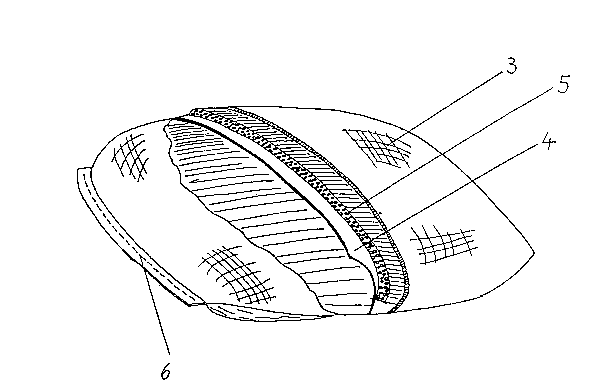
Fig. 2 shows the cross-section of a tank with a heat-insul~ting layer placed
between a tube-shaped layer made of tear-resistant fabric and a tube-shaped waterproof
Inner layer.

9 ~ ~-
A preferred version of the invention is shown in Fig. 1. The outer sheath, made
of a flexible, tear-resistant polypropylene fabric (3) is sealed at its ends with crosswise
seams (6). The object of the invention serves in the shown version as a water deposit.
Because of its large dimensions (4m x 2.5m x 0.3m) it has a capacity of 3m3 which in
5 the shown application example is being used as supply for drinking and washing water
in a camp. Ihrough the inlet valve (1), rain and dew water are being introduced. The
tapping takes place through outlet valves (2) with a diameter of approximately 5 cm.
This large diameter is necessary because the water flows out nearly without pressure.
The number of outlet valves is determined by the demand of water per time unit.
Another preferred version of the invention is shown in Fig. 2. An outer tank
sheath (3) made of a tube-shaped, highly tear-resistant fabr;c covers a thin-walled
polyethylene tube (4). A heat-insulating layer (5) is placed between the two. This heat-
insulating layer (5) can, ~or exarnple, protect a water tank against undesired cooling or a
tsnk with diesel fuel agadnst rndesired cooling or rmdesired heating.

Dessin représentatif
Une figure unique qui représente un dessin illustrant l'invention.
États administratifs

2024-08-01 : Dans le cadre de la transition vers les Brevets de nouvelle génération (BNG), la base de données sur les brevets canadiens (BDBC) contient désormais un Historique d'événement plus détaillé, qui reproduit le Journal des événements de notre nouvelle solution interne.

Veuillez noter que les événements débutant par « Inactive : » se réfèrent à des événements qui ne sont plus utilisés dans notre nouvelle solution interne.

Pour une meilleure compréhension de l'état de la demande ou brevet qui figure sur cette page, la rubrique Mise en garde , et les descriptions de Brevet , Historique d'événement , Taxes périodiques et Historique des paiements devraient être consultées.

Historique d'événement

Description Date
Inactive : CIB de MCD 2006-03-11
Demande non rétablie avant l'échéance 2003-03-14
Le délai pour l'annulation est expiré 2003-03-14
Inactive : Abandon. - Aucune rép dem par.30(2) Règles 2002-08-14
Réputée abandonnée - omission de répondre à un avis sur les taxes pour le maintien en état 2002-03-14
Inactive : Dem. de l'examinateur par.30(2) Règles 2002-02-14
Lettre envoyée 1998-04-29
Inactive : Renseign. sur l'état - Complets dès date d'ent. journ. 1998-04-28
Inactive : Dem. traitée sur TS dès date d'ent. journal 1998-04-28
Exigences pour une requête d'examen - jugée conforme 1998-03-26
Toutes les exigences pour l'examen - jugée conforme 1998-03-26
Demande publiée (accessible au public) 1994-09-16

Historique d'abandonnement

Date d'abandonnement Raison Date de rétablissement
2002-03-14

Taxes périodiques

Le dernier paiement a été reçu le 2001-02-16

Avis : Si le paiement en totalité n'a pas été reçu au plus tard à la date indiquée, une taxe supplémentaire peut être imposée, soit une des taxes suivantes :

  • taxe de rétablissement ;
  • taxe pour paiement en souffrance ; ou
  • taxe additionnelle pour le renversement d'une péremption réputée.

Veuillez vous référer à la page web des taxes sur les brevets de l'OPIC pour voir tous les montants actuels des taxes.

Historique des taxes

Type de taxes Anniversaire Échéance Date payée
TM (demande, 4e anniv.) - petite 04 1998-03-16 1998-03-09
Requête d'examen - petite 1998-03-26
TM (demande, 5e anniv.) - petite 05 1999-03-15 1999-01-29
TM (demande, 6e anniv.) - petite 06 2000-03-14 2000-02-23
TM (demande, 7e anniv.) - petite 07 2001-03-14 2001-02-16
Titulaires au dossier

Les titulaires actuels et antérieures au dossier sont affichés en ordre alphabétique.

Titulaires actuels au dossier
JORGE LOPEZ BLUMENKRON
Titulaires antérieures au dossier
S.O.
Les propriétaires antérieurs qui ne figurent pas dans la liste des « Propriétaires au dossier » apparaîtront dans d'autres documents au dossier.
Documents

Pour visionner les fichiers sélectionnés, entrer le code reCAPTCHA :


Pour visualiser une image, cliquer sur un lien dans la colonne description du document. Pour télécharger l'image (les images), cliquer l'une ou plusieurs cases à cocher dans la première colonne et ensuite cliquer sur le bouton "Télécharger sélection en format PDF (archive Zip)" ou le bouton "Télécharger sélection (en un fichier PDF fusionné)".

Liste des documents de brevet publiés et non publiés sur la BDBC .

Si vous avez des difficultés à accéder au contenu, veuillez communiquer avec le Centre de services à la clientèle au 1-866-997-1936, ou envoyer un courriel au Centre de service à la clientèle de l'OPIC.


Description du
Document 
Date
(aaaa-mm-jj) 
Nombre de pages   Taille de l'image (Ko) 
Dessin représentatif 1998-08-24 1 23
Page couverture 1995-04-08 1 68
Abrégé 1995-04-08 1 45
Dessins 1995-04-08 2 96
Revendications 1995-04-08 2 99
Description 1995-04-08 4 263
Accusé de réception de la requête d'examen 1998-04-29 1 178
Courtoisie - Lettre d'abandon (taxe de maintien en état) 2002-04-11 1 182
Courtoisie - Lettre d'abandon (R30(2)) 2002-10-23 1 168
Correspondance de la poursuite 1998-03-26 2 63
Taxes 1997-04-10 1 36
Taxes 1997-03-21 2 112
Taxes 1996-03-06 1 56