Sélection de la langue

Search

Sommaire du brevet 2119400 

Énoncé de désistement de responsabilité concernant l'information provenant de tiers

Une partie des informations de ce site Web a été fournie par des sources externes. Le gouvernement du Canada n'assume aucune responsabilité concernant la précision, l'actualité ou la fiabilité des informations fournies par les sources externes. Les utilisateurs qui désirent employer cette information devraient consulter directement la source des informations. Le contenu fourni par les sources externes n'est pas assujetti aux exigences sur les langues officielles, la protection des renseignements personnels et l'accessibilité.

Disponibilité de l'Abrégé et des Revendications

L'apparition de différences dans le texte et l'image des Revendications et de l'Abrégé dépend du moment auquel le document est publié. Les textes des Revendications et de l'Abrégé sont affichés :

  • lorsque la demande peut être examinée par le public;
  • lorsque le brevet est émis (délivrance).
(12) Brevet: (11) CA 2119400
(54) Titre français: MECANISME DE COMMANDE POUR PORTE OU FENETRE
(54) Titre anglais: SLEEVE ACTUATOR FOR A WINDOW OR A DOOR
Statut: Périmé et au-delà du délai pour l’annulation
Données bibliographiques
(51) Classification internationale des brevets (CIB):
  • E05F 11/14 (2006.01)
  • E05B 15/00 (2006.01)
  • E05B 15/04 (2006.01)
  • E05B 63/00 (2006.01)
  • E05C 9/02 (2006.01)
  • E05C 9/12 (2006.01)
(72) Inventeurs :
  • GOLDSCHMIDT, HANS-GERD (Allemagne)
(73) Titulaires :
  • SCHUCO INTERNATIONAL KG
  • GEBR. GOLDSCHMIDT BAUBESCHLAGE GMBH
(71) Demandeurs :
  • SCHUCO INTERNATIONAL KG (Allemagne)
  • GEBR. GOLDSCHMIDT BAUBESCHLAGE GMBH (Allemagne)
(74) Agent: SMART & BIGGAR LP
(74) Co-agent:
(45) Délivré: 2004-12-14
(22) Date de dépôt: 1994-03-18
(41) Mise à la disponibilité du public: 1994-09-20
Requête d'examen: 2001-02-22
Licence disponible: S.O.
Cédé au domaine public: S.O.
(25) Langue des documents déposés: Anglais

Traité de coopération en matière de brevets (PCT): Non

(30) Données de priorité de la demande:
Numéro de la demande Pays / territoire Date
P 43 08 810.4 (Allemagne) 1993-03-19

Abrégés

Abrégé anglais


A locking mechanism for driving a lock bolt
comprises a housing. A pinion has an outer circumference
and is rotatably mounted in the housing. The pinion has a
plurality of teeth arid tooth gaps are disposed between
adjacent teeth. A predetermined number of the tooth gaps
have an abutment that extends outwardly substantially to the
outer circumference of the pinion. A toothed rod is coupled
to the lock bolt. The toothed rod is engaged by the pinion.
A spring loaded detent device arrest the rotational movement
of the detent in a switching position of the lock bolt.

Revendications

Note : Les revendications sont présentées dans la langue officielle dans laquelle elles ont été soumises.


CLAIMS:
1. A locking mechanism for driving a lock bolt comprising:
a housing;
a pinion having an outer circumference and being rotatably
mounted in said housing, said pinion having a plurality of
teeth and tooth gaps disposed between adjacent teeth, a
predetermined number of said tooth gaps having an abutment
that extends outwardly substantially to the outer
circumference of said pinion;
a slider having a plurality of teeth, said slider meshing
with said pinion;
a toothed rod being coupled to said lock bolt, said toothed
rod being engaged by said slider with said pinion, said
slider having a recess to receive said abutment; and
spring loaded detent means for arresting the rotational
movement of said pinion in a switching position of said lock
bolt.
2. The locking mechanism of claim 1, wherein said spring
loaded detent means comprises two mutually opposite, spring-
loaded detent members.
3. The locking mechanism of claim 1, wherein said abutment
is a wall web disposed between two adjacent teeth.
4. The locking mechanism of claim 3, wherein said wall web
is disposed in a center plane, said center plane extends
perpendicular to a rotational axis of said pinion.
8

5. The locking mechanism of claim 3, wherein a plurality of
wall webs are disposed in the respective tooth gaps of said
pinion.
6. The locking mechanism of claim 1, further comprising a
handle, said handle being equipped with a spring-loaded
catch which engages a recess of said pinion.
7. The locking mechanism of claim 6, wherein said recess, in
a predetermined position of the mechanism, extends through
the slider and the toothed rod to the outside of said
housing.
9

Description

Note : Les descriptions sont présentées dans la langue officielle dans laquelle elles ont été soumises.

CA 02119400 2004-03-30
23724-211
LOCKING MECHANISM FOR WINDOWS OR DOORS
FIELD OF THE INVENTION
The present invention relates to a locking
mechanism disposed in the sash of a window or a door to
drive a lock-bolt fitting. More specifically, the present
invention is directed to a locking mechanism with a handle,
which is rotatably mounted on the frame, for activating a
pinion that engages a toothed rod, such that the toothed rod
is coupled to the lock bolts.
BACKGROUND OF THE INVENTION
A drive of this type is known for example from
DE-88 14 754.1 U1, in which the locking mechanism with its
associated housing has a great structural height, so that
the sash, which is made from extruded cavity profiles, must
be milled out. The pinion is mounted in the housing of the
mechanism, and is activated by the handle. The pinion
engages the toothed rod, which is coupled to the lock bolts
of the fitting.
Most mechanisms for activating a side/bottom hung
sash window or door have the common feature that the handle
permits a rotation angle of 180°, within which the lock bolt
fitting can be moved from its locking position, through the
rotational position, into the tilted position.
SUMMARY OF THE INVENTION
It is an object of the present invention to design
a locking mechanism of the type mentioned in the
introduction in such a way as to achieve, with minimal
structural complication, a process for arresting the
lock-bolt fitting in those switching positions which
1

CA 02119400 2004-03-30
23724-211
represent the locking position, the rotation position, and
the tilt position for a side/bottom hung sash window or
door.
According to the present invention, this object is
achieved in such a way that the pinion can be arrested in
the switching positions of the lock-bolt fitting through a
spring-loaded detent device which engages the tooth gaps of
the pinion. The remaining tooth gaps of the pinion have an
abutment for the spring-loaded detent means that, extend
outwardly as far as, or almost as far, as the outer
circumference of the pinion.
The abutment guarantees that the spring-loaded
detent means can engage only those tooth gaps of the pinion
which correspond to a switching position of the lock-bolt
fitting.
According to the invention there is provided a
locking mechanism for driving a lock bolt comprising: a
housing; a pinion having an outer circumference and being
rotatably mounted in said housing, said pinion having a
plurality of teeth and tooth gaps disposed between adjacent
teeth, a predetermined number of said tooth gaps having an
abutment that extends outwardly substantially to the outer
circumference of said pinion; a slider having a plurality of
teeth, said slider meshing with said pinion; a toothed rod
being coupled to said lock bolt, said toothed rod being
engaged by said slider with said pinion, said slider having
a recess to receive said abutment; and spring loaded detent
means for arresting the rotational movement of said pinion
in a switching position of said lock bolt.
2

CA 02119400 2004-03-30
23724-211
BRIEF DESCRIPTION OF THE DRAWINGS
The above and still further objects, features and
advantages of the present invention will become apparent
upon consideration of the following detailed description of
a specific embodiment thereof, especially when taken in
conjunction with the accompanying drawings wherein like
reference numerals in the various figures are utilized to
designate like components, and wherein:
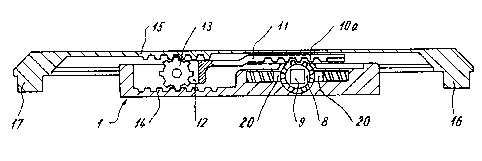
FIG. 1 is a longitudinal section of a locking
mechanism with its associated toothed rod according to the
present invention;
FIG. 2 is an enlarged longitudinal section of the
output pinion of the locking mechanism with its associated
mechanical parts;
FIG. 3 is a sectional view taken along
line III--III of FIG. 2;
FIG. 4 is an enlarged longitudinal section of the
pinion, which can be driven by the handle, with its
associated mechanical parts;
FIG. 5 is a sectional view taken along line V--V
of FIG. 4;
FIG. 6 is a longitudinal sectional view through
the sash profile on the handle side with a built-in locking
mechanism;
FIG. 7 is a sectional view of the pinion that can
be activated by the handle, in its installed position;
FIG. 8 is a perspective view of the pinion.
3

CA 02119400 2004-03-30
23724-211
DETAILED DESCRIPTION OF PRESENT INVENTION
Referring now to FIG. 1, the locking mechanism of
the present invention includes a housing 1. As illustrated
in FIG. 3, housing 1 can be divided longitudinally and
equipped with longitudinal grooves 2, 3, so that the housing
can be pushed into a groove 4, designed to receive the
housing 1 and disposed, for example, in the sash profile 5
of a window or a door on the handle side. The edge strips 6
of the groove 4 engage the longitudinal grooves 2 and 3,
respectively.
A pinion 8, which can be activated by a handle 7,
is rotatably mounted in the housing 1. Pinion 8 has a
square recess 9 to receive a square extension 10 of the
handle 7. Pinion 8 engages a row of teeth l0a that is part
of a slider mechanism 11 that can move linearly. Slide 11
is equipped with a fork piece 12, within which an output
pinion 13 is rotatably mounted. Output pinion 13 engages a
row or rack of teeth 14 that are fixed in the housing and
meshes with a toothed rod 15. Toothed rod 15 has journals
16, 17 at its ends, which are introduced into the holes of
lock bolts 27, 28, so that the motion of the toothed rod 15
is transferred to these lock bolts.
Referring now to FIG. 5, the toothed rod 15 is
illustrated as being divided longitudinally and has a
U-shaped cross section. The toothed rod 15 covers one side
of the housing 1. Toothed rod 15 has guide strips 18, which
extend inwardly, and engage a second pair of longitudinal
grooves of the housing 1 which are disposed next to the
upper limit edge of the side walls of the housing 1.
FIG. 5 further shows that the housing 1, in its
built-in position, extending close to the base 19 of the
4

CA 02119400 2004-03-30
23724-211
groove 4, in the sash profile 5. In the open side of the
groove 4, toothed rod 15 extends into the chamber between
the sash and the frame. Thus, additional recesses in the
sash profile to accommodate the housing and its associated
toothed rod 15 are not necessary.
FIGS. 4 and 5 show the mounting of the pinion 8 in
a magnified representation. The head diameter of the pinion
is rotatably mounted in a hole of the housing l, such that
spring-loaded detent device 20 engages the tooth gaps of the
pinion 8, and thus arrest the handle 7 in its switching
positions and make these positions perceptible to the user.
Pinion 8 has bearing protrusions 21 relative to
the root circle of the toothing, to assure a good,
load-transmitting bearing to the housing 1. Because the
housing 1 is divided longitudinally, no additional
precautions need to be taken for axially limiting the
pinion 8, since the bearing protrusions 21 also form the
axial limitation in the housing 1.
The square recess 9 of the pinion 8 is open toward
the stop side of the window sash, so that the square
extension 10 of the handle can be pushed in through an
appropriate recess 22 in the sash profile 5 thus, the
mechanism is also fixed in the longitudinal direction of the
groove 4.
A spring-loaded action catch 23 is provided in the
square 10 for axially fixing the handle 7. The catch 23 is
received in a recess 24 of the pinion 8. The recess 24
extends into the square recess 9. When the mechanism is in
its middle position, recess 24 extends from the pinion 8,
through slider 11 and through toothed rod 15, to the
outside. It is thus possible to activate catch 23 through a
5

CA 02119400 2004-03-30
23724-211
mandrel, so that the handle with its square 10 can be
uncoupled or disconnected from pinion 8.
FIGS. 2 and 3 show the mounting of the pinion 13
in the forked piece 12, which has two bearing flanges 25 to
receive the bearing bolt pin 26 of the pinion 13. Slider 11
is guided in that region of the toothed rod 15 which is
equipped with the row of teeth 10a. Slide 11 is
additionally guided by means of the bearing flanges 25 in
the housing 1.
The mechanism is shown in its built-in position in
FIG. 6. The journals 16, 17 of the toothed rod 15 engage
the holes on the end side of the lock bolts 27, 28. These
lock bolts are guided in the groove 4.
In the illustrated embodiment, the locking
mechanism is equipped with two mutually opposite, spring-
loaded detent devices 20. When the lock-bolt fitting is in
a switching position, these detent means mesh with the tooth
gaps as illustrated in FIG. 7. FIGS. 7 and 8 show a wall
web 29 that is disposed in every other tooth gap of the
pinion 8. As the pinion is turned, wall web 29 prevents the
detent means 20 from catching in these tooth gaps, which do
not correspond to any switching position of the lock-bolt
fitting. FIG. 8 shows that the wall webs 29, which connect
together two neighboring teeth, are preferably disposed in
the center plane which extends perpendicular to the axis of
the pinion 8.
In a modification of this design, it is also
conceivable that several mutually parallel wall webs can be
provided in the tooth gaps described above, or that an
abutment with a different geometry can be provided instead
of these wall webs. Such an abutment should extend as far
6

CA 02119400 2004-03-30
23724-211
as, or nearly as far as, the outer circumference of the
pinion 8 and prevents the detent device 20 from entering the
tooth gaps while the pinion turns from one switching
position to the next.
Since a row of teeth l0a works together with the
pinion 8, and since the motion of the pinion must also be
transmitted to the toothed rod 15 and the engagement of the
pinion with the toothed rod 15 must not be impaired, it is
necessary to equip the row of teeth or the toothed rod with
a recess which receives the wall webs 29 or other abutments
of a different shape, disposed in the tooth gaps of the
pinion, while the pinion is undergoing its rotational
motion.
The wall web 29 is disposed in the center plane
which extends perpendicular to the axis of the pinion 8 and
engages a corresponding longitudinal recess in the row of
teeth 10a of the slider 11. This recess provides a lateral
guide between the pinion 8 and the slider 11.
7

Dessin représentatif
Une figure unique qui représente un dessin illustrant l'invention.
États administratifs

2024-08-01 : Dans le cadre de la transition vers les Brevets de nouvelle génération (BNG), la base de données sur les brevets canadiens (BDBC) contient désormais un Historique d'événement plus détaillé, qui reproduit le Journal des événements de notre nouvelle solution interne.

Veuillez noter que les événements débutant par « Inactive : » se réfèrent à des événements qui ne sont plus utilisés dans notre nouvelle solution interne.

Pour une meilleure compréhension de l'état de la demande ou brevet qui figure sur cette page, la rubrique Mise en garde , et les descriptions de Brevet , Historique d'événement , Taxes périodiques et Historique des paiements devraient être consultées.

Historique d'événement

Description Date
Le délai pour l'annulation est expiré 2009-03-18
Lettre envoyée 2008-03-18
Inactive : CIB de MCD 2006-03-11
Accordé par délivrance 2004-12-14
Inactive : Page couverture publiée 2004-12-13
Préoctroi 2004-09-28
Inactive : Taxe finale reçue 2004-09-28
Lettre envoyée 2004-09-01
Un avis d'acceptation est envoyé 2004-09-01
Inactive : Approuvée aux fins d'acceptation (AFA) 2004-08-19
Modification reçue - modification volontaire 2004-03-30
Inactive : Dem. de l'examinateur par.30(2) Règles 2003-10-02
Inactive : Dem. traitée sur TS dès date d'ent. journal 2001-03-09
Lettre envoyée 2001-03-09
Inactive : Renseign. sur l'état - Complets dès date d'ent. journ. 2001-03-09
Toutes les exigences pour l'examen - jugée conforme 2001-02-22
Exigences pour une requête d'examen - jugée conforme 2001-02-22
Demande publiée (accessible au public) 1994-09-20

Historique d'abandonnement

Il n'y a pas d'historique d'abandonnement

Taxes périodiques

Le dernier paiement a été reçu le 2004-02-17

Avis : Si le paiement en totalité n'a pas été reçu au plus tard à la date indiquée, une taxe supplémentaire peut être imposée, soit une des taxes suivantes :

  • taxe de rétablissement ;
  • taxe pour paiement en souffrance ; ou
  • taxe additionnelle pour le renversement d'une péremption réputée.

Veuillez vous référer à la page web des taxes sur les brevets de l'OPIC pour voir tous les montants actuels des taxes.

Historique des taxes

Type de taxes Anniversaire Échéance Date payée
TM (demande, 4e anniv.) - générale 04 1998-03-18 1998-02-23
TM (demande, 5e anniv.) - générale 05 1999-03-18 1999-03-05
TM (demande, 6e anniv.) - générale 06 2000-03-20 2000-02-07
Requête d'examen - générale 2001-02-22
TM (demande, 7e anniv.) - générale 07 2001-03-19 2001-02-28
TM (demande, 8e anniv.) - générale 08 2002-03-18 2002-02-21
TM (demande, 9e anniv.) - générale 09 2003-03-18 2003-02-04
TM (demande, 10e anniv.) - générale 10 2004-03-18 2004-02-17
Taxe finale - générale 2004-09-28
TM (brevet, 11e anniv.) - générale 2005-03-18 2005-02-22
TM (brevet, 12e anniv.) - générale 2006-03-20 2006-03-09
TM (brevet, 13e anniv.) - générale 2007-03-19 2007-02-27
Titulaires au dossier

Les titulaires actuels et antérieures au dossier sont affichés en ordre alphabétique.

Titulaires actuels au dossier
SCHUCO INTERNATIONAL KG
GEBR. GOLDSCHMIDT BAUBESCHLAGE GMBH
Titulaires antérieures au dossier
HANS-GERD GOLDSCHMIDT
Les propriétaires antérieurs qui ne figurent pas dans la liste des « Propriétaires au dossier » apparaîtront dans d'autres documents au dossier.
Documents

Pour visionner les fichiers sélectionnés, entrer le code reCAPTCHA :


Pour visualiser une image, cliquer sur un lien dans la colonne description du document. Pour télécharger l'image (les images), cliquer l'une ou plusieurs cases à cocher dans la première colonne et ensuite cliquer sur le bouton "Télécharger sélection en format PDF (archive Zip)" ou le bouton "Télécharger sélection (en un fichier PDF fusionné)".

Liste des documents de brevet publiés et non publiés sur la BDBC .

Si vous avez des difficultés à accéder au contenu, veuillez communiquer avec le Centre de services à la clientèle au 1-866-997-1936, ou envoyer un courriel au Centre de service à la clientèle de l'OPIC.


Description du
Document 
Date
(aaaa-mm-jj) 
Nombre de pages   Taille de l'image (Ko) 
Dessin représentatif 1998-08-26 1 9
Abrégé 1995-04-08 1 60
Page couverture 1995-04-08 1 50
Revendications 1995-04-08 2 94
Description 1995-04-08 6 308
Abrégé 2004-03-30 1 15
Description 2004-03-30 7 252
Revendications 2004-03-30 2 46
Dessin représentatif 2004-08-19 1 8
Dessins 1995-04-08 4 61
Page couverture 2004-11-10 1 36
Rappel - requête d'examen 2000-11-21 1 119
Accusé de réception de la requête d'examen 2001-03-09 1 179
Avis du commissaire - Demande jugée acceptable 2004-09-01 1 160
Avis concernant la taxe de maintien 2008-04-29 1 172
Correspondance 2004-09-28 1 31
Taxes 1997-02-24 1 40
Taxes 1996-02-28 1 42