Sélection de la langue

Search

Sommaire du brevet 2120971 

Énoncé de désistement de responsabilité concernant l'information provenant de tiers

Une partie des informations de ce site Web a été fournie par des sources externes. Le gouvernement du Canada n'assume aucune responsabilité concernant la précision, l'actualité ou la fiabilité des informations fournies par les sources externes. Les utilisateurs qui désirent employer cette information devraient consulter directement la source des informations. Le contenu fourni par les sources externes n'est pas assujetti aux exigences sur les langues officielles, la protection des renseignements personnels et l'accessibilité.

Disponibilité de l'Abrégé et des Revendications

L'apparition de différences dans le texte et l'image des Revendications et de l'Abrégé dépend du moment auquel le document est publié. Les textes des Revendications et de l'Abrégé sont affichés :

  • lorsque la demande peut être examinée par le public;
  • lorsque le brevet est émis (délivrance).
(12) Demande de brevet: (11) CA 2120971
(54) Titre français: OUTIL SERVANT A POSITIONNER DANS UN CYLINDRE LE DISPOSITIF UTILISE POUR EN MESURER LE DIAMETRE INTERIEUR
(54) Titre anglais: CENTERING TOOL FOR CYLINDER GAUGES
Statut: Réputée abandonnée et au-delà du délai pour le rétablissement - en attente de la réponse à l’avis de communication rejetée
Données bibliographiques
Abrégés

Abrégé anglais


A centering tool that adapts to cylinder gauges to provide
a fast, accurate one-time reading of the cylinder gauge. The
centering tool provides adjustable interalignment elements to
provide positive positioning of the gauge within the interior
of the cylinder bore to determine the interior I.D. of the
cylinder.

Revendications

Note : Les revendications sont présentées dans la langue officielle dans laquelle elles ont été soumises.


CLAIMS
1. In combination a centering tool for use with
telescopic cylinder wall gauges to measure inside diameter,
said telescopic cylinder wall gauges comprises a T-shaped
mounting body, an elongated tubular handle extending
therefrom, a locking screw on the end of said handle, a pair
of oppositely disposed spring loaded contact plungers
extending from said mounting body, said centering tool
comprises; a mounting base having spaced annularly disposed
apertured mounting surfaces, centering pins registerably
secured within said respectively mounting surfaces. A bore
extending through said mounting base horizontally aligned
with said centering pins, means for aligning and secure said
centering tool on said T-shaped mounting body of said
telescopic cylinder wall gauge.
2. The centering tool for claim 1 wherein said
mounting base has co-planar top and bottom surfaces, said
angularly engaged mounting surfaces extending between said
top and bottom surfaces.
-9-

3. The centering tool of claim 1 wherein said means
for aligning and securing said centering tool on said
T-shaped mounting body of said telescopic cylinder wall
gauge comprises; a notched area in said mounting body,
between said mounting surfaces and intersecting said bore in
said mounting base.
4. A centering took gauge for use in measuring inside
diameter of a cylinder surface, said cylinder tool gauge
comprises a mounting base, having spaced apertured contact
pin mounting surfaces, an elongated tubular handle extending
from said mounting base, a locking screw on the end of said
handle, a pair of opposing telescopically extensible contact
plungers extending from said mounting base, centering pins
registerable in fixed relation within said contact pin
mounting surfaces, said centering pins in offset angular
relation to said telescopically extensible contact plungers.
-10-

Description

Note : Les descriptions sont présentées dans la langue officielle dans laquelle elles ont été soumises.

2120~7~
CENTERING TOOL FOR CYLINDER GAUGE
Background of the Invention
Technical Field:
This device relates to telescopic gauges that are used to
transfer the interdimensions of a cylinder for measuring
purposes within thousandths of an inch.
Description of Prior Art:
Prior art devices of this type have relied on a variety of
different structural configurations that are adapted to provide
automatic centering of measuring gauges within cylinders.
Examples of such are U.S. Patents 2,470,635, 3,836,277,
4,754,551 and 4,773,164.
Commercial examples of self-centering gauges are shown in
cylinder gauges nos. 452B and 84 in Starrett ~ catalog and
bore gauge series 511-526 by Mitutoyo catalog, page 285.
Telescopic gauges of this type to which the invention is
designed to adapt to are shown in Starrett catalog, page 131
(telescopic gauge no. 829 and 579 series). The telescoping
gauges no. 579 series are used to transfer internal
measurements from the cylinder to be measured with precision

2120971
calibers. These gauges have opposite telescopically extensible
spring-urged contact plungers that can be locked once within
the cylinder and then removed and measured.
In one form of applicant's invention, the centering tool
is adapted to be fitted over and adapted to one of the plunger
supports providing a pair of angularly offset guide pins to
center the gauge within the cylinder without multiple efforts.
In cylinder bore gauges no. 511-164 of Mitutoyo reference
and 84 of Starrett page 364 series self-contained measuring
gauges and cylinder engagement surfaces are shown wherein the
gauges measure directly the distance between the contact points
that extend outwardly from the gauge head. Bore gauge 84
series has a fixed pin opposite a measuring plunger with two
positioning pins in offset angular relation th~ereto.
In U.S. Patent 2,470,635 a gauge is positioned on a
central shaft. The gauge has a pair of chucks with resilient
jaws extending therefrom.
In U.S. Patent 3,836,277 a centering tool is disclosed
wherein a tool is centered within a cylinder by multiple pins
on the respective spring-urged arms pivoted about and to the

- 2120~71
tool.
U.S. Patent 4,754,551 is directed to a centering gauge
tool in which multiple sensing fingers are mounted on a conical
insert and expand outwardly to engage the inner surface,
centering and measuring the tool.
In U.S. Patent 4,773,164 a self-aligning caliber bar is
disclosed in which two sets of aligned spaced pivoting fingers
extend outwardly from a central mounting body to align same
within a cylinder enclosure.
Summary of the Invention
A centering device to pre-position a cylinder gauge within
a cylinder to be measured. The centering device is adjustable
to conform with multiple cylinder dimensions by a pair of
interchangeable centering pins extending on either side of one
of the gauges contact plungers providing a fast accurate one
time positioning of the gauge within the cylinder.
Description of the Drawings
Figure 1 is a perspective view of a telescopic cylinder
gauge with the invention position thereon;
Figure 2 is an enlarged top plan view of the centering

2120971
tool;
Figure 3 is an enlarged front plan view of the centering
tool;
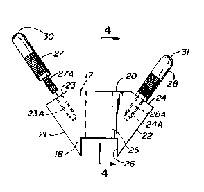
Figure 4 is an enlarged cross-sectional view on lines 4-4
of Figure 2;
Figure 5 is a top plan view of the centering device
positioned on a telescopic gauge within a cylinder
representation in use;
Figure 6 is an enlarged side plan view of a guide pin; and
Figure 7 is an enlarged side plan view of an alternate
guide pin configuration.
Description of the Preferred Embodiment
Referring to figure 1 of the drawings, a centering device
10 can be seen positioned on a telescopic gauge 11, shown in
broken lines, having an elongated tubular handle portion 12
with a locking screw 13 on one end and a T-shaped mounting body
14 on the opposite end thereof. A pair of telescopically
extensible contact plungers 15 and 16 are movably positioned
within said mounting body 14 at right angles to said
hereinbefore disclosed handle portion 12. The centering device

- 212097 1
10 is shown positioned on the mounting body 14 and is best seen
in figures 2-4 of the drawings having a generally triangular
mounting base 17 with corresponding parallel top and bottom
surfaces 18 and 19. Multiple angular disposed side surfaces
are defined on said mounting base 17 as a mounting surface 20,
opposing angular inclined surfaces 21 and 22 and pin mounting
surfaces 23 and 24 therebetween.
The mounting surface 20 has a bore 25 extending through
said mounting base 17 exiting same within a notched area at 26
between said respective surfaces 21 and 22. Each of said pin
mounting surface 23 and 24 have threaded bores 23A and 24A
respectively for selective registration with centering pins 27
and 28, best seen in figures 1,2,4, and 6 of the drawings.
Each of the centering pins 27 and 28 have respective threaded
mounting shafts 27A and 28A with rounded cylinder engagement
oppositely disposed ends 30 and 31.
For use, the centering device is positioned over one end
of the mounting body 14 by friction fit with the contact
plunger 16 extending through the bore 25 within the notched
area 26 abutting same adjacent the handle portion 12

2120971
hereinbefore described as seen in figure 1 of the drawings.
Once positioned, the centering device 10 is integral with said
telescopic gauge 11 as best seen in figure 1 of the drawings.
The centering pins 27 and 28 are thus positioned in spaced
offset angular relation to said contact plunger 16 defining a
generally triangular configuration therebetween, best seen in
figure 5 of the drawings. By defining multiple spaced fixed
contact points 29 and 30 within an interior surface wall 31 of
a cylinder 32, the telescopic gauge 11 is perfectly centered to
obtain an accurate first time reading by engagement with the
respective contact plungers 15 and 16 against the opposing
interior surface wall 31 of the cylinder 32.
Referring now to figure 6 of the drawings, a centering pin
27 can be seen with a portion in cross-section defining the
solid nature of the centering pin construction at 33.
Referring to figure 7 of the drawings, an alternate
centering pin 34 can be seen wherein the overall length
indicated by L1 is proportionally greater than that of the
centering pins 27 and 28 as illustrated by L2 hereinbefore
described.

~1209~1
It will be apparent to those skilled in the art that in
order to accommodate a variety of cylinder sizes, alternate
centering pins must be provided that will mount within the
respective threaded bores 23A and 24A in said mounting body 17.
During the gauging of the cylinder, the telescopic gauge
11 with the centering device 10 of the invention attached will
be automatically centered within the cylinder 32 by the
centering pins 27 and 28 as hereinbefore described so that the
contact plungers 15 and 16 will adjust to the interior surface
wall 31 at aligned opposing contact points 35 and 36 then
locked in that position by rotation of the locking screw 13.
The telescopic gauge 11 is then removed from the cylinder 32
for measuring.
It will be evident to those skilled in the art that the
centering device 10 can be permanently attached to the
telescopic gauge 11 during manufacturing of same or alternately
affixed to the telescopic gauge 11 as an aftermarket accessory
as hereinbefore disclosed.
Thus, having illustrated and described my invention, it
~0 will be apparent to those skilled in the art that various

2~20~71
changes and modifications may be made therein without departing
from the spirit of the invention, therefore I claim:

Dessin représentatif
Une figure unique qui représente un dessin illustrant l'invention.
États administratifs

2024-08-01 : Dans le cadre de la transition vers les Brevets de nouvelle génération (BNG), la base de données sur les brevets canadiens (BDBC) contient désormais un Historique d'événement plus détaillé, qui reproduit le Journal des événements de notre nouvelle solution interne.

Veuillez noter que les événements débutant par « Inactive : » se réfèrent à des événements qui ne sont plus utilisés dans notre nouvelle solution interne.

Pour une meilleure compréhension de l'état de la demande ou brevet qui figure sur cette page, la rubrique Mise en garde , et les descriptions de Brevet , Historique d'événement , Taxes périodiques et Historique des paiements devraient être consultées.

Historique d'événement

Description Date
Demande non rétablie avant l'échéance 2000-12-04
Inactive : Morte - Aucune rép. dem. par.30(2) Règles 2000-12-04
Réputée abandonnée - omission de répondre à un avis sur les taxes pour le maintien en état 2000-04-11
Inactive : Renseign. sur l'état - Complets dès date d'ent. journ. 2000-02-23
Inactive : Abandon. - Aucune rép dem par.30(2) Règles 1999-12-02
Inactive : Dem. de l'examinateur par.30(2) Règles 1999-09-02
Inactive : Demande ad hoc documentée 1997-04-11
Réputée abandonnée - omission de répondre à un avis sur les taxes pour le maintien en état 1997-04-11
Demande publiée (accessible au public) 1995-10-12
Toutes les exigences pour l'examen - jugée conforme 1994-04-11
Exigences pour une requête d'examen - jugée conforme 1994-04-11

Historique d'abandonnement

Date d'abandonnement Raison Date de rétablissement
2000-04-11
1997-04-11

Taxes périodiques

Le dernier paiement a été reçu le 1999-04-09

Avis : Si le paiement en totalité n'a pas été reçu au plus tard à la date indiquée, une taxe supplémentaire peut être imposée, soit une des taxes suivantes :

  • taxe de rétablissement ;
  • taxe pour paiement en souffrance ; ou
  • taxe additionnelle pour le renversement d'une péremption réputée.

Veuillez vous référer à la page web des taxes sur les brevets de l'OPIC pour voir tous les montants actuels des taxes.

Historique des taxes

Type de taxes Anniversaire Échéance Date payée
TM (demande, 4e anniv.) - petite 04 1998-04-14 1998-04-07
TM (demande, 5e anniv.) - petite 05 1999-04-12 1999-04-09
Titulaires au dossier

Les titulaires actuels et antérieures au dossier sont affichés en ordre alphabétique.

Titulaires actuels au dossier
DAVID ISLER
Titulaires antérieures au dossier
S.O.
Les propriétaires antérieurs qui ne figurent pas dans la liste des « Propriétaires au dossier » apparaîtront dans d'autres documents au dossier.
Documents

Pour visionner les fichiers sélectionnés, entrer le code reCAPTCHA :


Pour visualiser une image, cliquer sur un lien dans la colonne description du document. Pour télécharger l'image (les images), cliquer l'une ou plusieurs cases à cocher dans la première colonne et ensuite cliquer sur le bouton "Télécharger sélection en format PDF (archive Zip)" ou le bouton "Télécharger sélection (en un fichier PDF fusionné)".

Liste des documents de brevet publiés et non publiés sur la BDBC .

Si vous avez des difficultés à accéder au contenu, veuillez communiquer avec le Centre de services à la clientèle au 1-866-997-1936, ou envoyer un courriel au Centre de service à la clientèle de l'OPIC.


Description du
Document 
Date
(aaaa-mm-jj) 
Nombre de pages   Taille de l'image (Ko) 
Page couverture 1996-01-24 1 13
Abrégé 1995-10-12 1 10
Revendications 1995-10-12 2 50
Description 1995-10-12 8 200
Dessins 1995-10-12 2 40
Dessin représentatif 1998-05-19 1 7
Courtoisie - Lettre d'abandon (R30(2)) 2000-02-22 1 171
Courtoisie - Lettre d'abandon (taxe de maintien en état) 2000-05-09 1 183
Taxes 1999-04-09 1 36
Taxes 1998-04-07 1 43
Taxes 1997-04-01 1 44
Taxes 1996-04-09 1 37
Correspondance reliée au PCT 1994-07-14 1 27
Correspondance reliée au PCT 1994-07-07 2 46
Demande de l'examinateur 1999-09-02 3 88
Courtoisie - Lettre du bureau 1994-06-29 1 17