Note : Les descriptions sont présentées dans la langue officielle dans laquelle elles ont été soumises.
2.~
TITLE OF THE INVENTION
SYNT}IETIC RESIN PELLETIZING MACHINE
BACKGROUND OF THE INVENTION
1. Field of the Invention
The present invention relates to a synthetic resin
pelletizing machine or pelletizer that shapes by extruding a
raw ~aterial, such as synthetic resin powder, granules or
pellets, into a continuous form of extrudate and, after
cooling the continuous extrudate, cuts off the same into
small pelle~s.
2. Description of the Prior Art:
In the synthetic resin molding industry, it is a
customary practice to mix a plurality of synthetic resin
materials of different properties to form a molded product
of desired characteristics. In this instance, if the mixing
is not homogeneous, the final product has undesired charac-
teristics. To avoid this problem, as disclosed in Japanese
Patent Publication No. 63-32604, each of various synthetic
resins are separately supplied to an extrusion unit in which
the each kind of resin is melted with heat and extruded as a
strand into a cooling water bath. The cooled strand is cut
into fine granules or pellets. The fine pellets thus pro-
duced are then mixed with similar pellets of different kinds
of synthetic resins to form a molded article.
In general, the conventional pelletizing machine
of the type concerned is, as also mentioned in the above-
referenced Japanese patent publication, a large-sized machine
to cope with the mass-production system. Accordingly, the
extrusion unit incorporated in such a large-sized pelletizing
machine is necessarily large in size, and taking the mainte-
nance into accoun-t, it is composed of a horizontal-type
extrusion unit having an extrusion cylinder horizontally
mounted on a machine frame.
The known pelletizing machine of the foregoing
construction occupies a large space in a horizontal direc-
-tion and, hence, uses the space inefficiently. In addition,
the known pelletizing machine is not adaptable to the mul-ti-
product, small-quantity production system which has recently
been required for various molded articles. An attempted use
of the conventional pelletizing machine in the multi-product9
small-quantity production system would produce an excessive
s-tock of molde~ articles, requiring a complicated stock con-
trol operation. Accordingly, there is a keen demand for a
pelleti~ing machine which is compact in size and readily
adaptable to the multi-product, small-quantity production
system. Furthermore, since -the raw resin is supplied to the
horizontal-type extrusion cylinder at right angles to the
axis of an extrusion screw, the raw resin is likely to get
clogged at an inlet of the extrusion cylinder. In addition,
' ;'` " ~ ' ' ' ''-,:,, ' ' ": . , " , : ` , - ,, '
-the strand, as it is ex~ruded from the horizontal-type
extrusion cylinder into a cooling bath, is subjected to a
la-teral bending force which will exert negative influence
on -the quality of the pellets produced from the extruded
s-trand.
SUMMARY OF THE INVENTION
It is, there-foreg an object of the present inven-
tion to provide a synthetic resin pelletizing machine
which is compac-t in size, readily adaptable to the mul-ti-
product, small-quantity production system, and capable of
assuring a smooth feed of raw resin to an extrusion unit as
well as a smooth passage of an extruded strand through a
cooling bath.
According to the present invention, there is pro-
vided a synthetic resin pelletizing machine of the type
having a molding portion in which a raw material including a
synthetic resin, a pigment and various additives is melted
and kneaded ancl then shaped by extrusion into a strand, and
the extruded strand is cooled, charac-teri~ed in that an
extrusion cylinder having at its lower end a die head forms,
with a horizontal plane, an installation angle H which is
in -the range of 0 < 0 <90 , a raw material feed passage ~
extends upwardly from said extrusion cylinder at a predeter- :
mined angle relative to a longitudinal axis of the extrusion
cylinder, and a cooling unit is disposed helow the die head
,'::.:, : ~: , : : ,
for cooling the strand, the cooling unit having a double
bath construction composed of a first cooling bath and a
second cooling bath disposed in the first cooling bath.
The extrusion cylinder is generally arranged verti-
cally and not horizontally, so that the pelleti,2ing machine
as a whole is compact in si~e and occupies a relatively
small space in the horizontal direction. Since the raw
material is supplied obliquely from the raw material feed
passage into the extrusion uni-t and enters toward the ex-
trusion direction, the extrusion cylinder is free from a
clogging problem which would otherwise occurs at an inlet
of the extrusion cylinder.
The pelletizing machine ordinarily includes a
cutting unit disposed at a downstream end of a strand feed
path in the cooling unit, for cutting the strand into pel-
lets of a predetermined size.
The installation angle O of the extrusion cylinder
relative to the hori~ontal plane is preferably in the range
of 45 < O <90 . In connection with the ins-tallation angle
~ , the angle between -the synthetic resin-chip feed passage
and the longitudinal axis of the extrusion cylinder is set
in the range of 0 to 45 .
In addition, the first and second cooling baths
contain cooling water, and the cooling water is circulated
through the first and second cooling baths by means of a
2"~ f, cs~1,)
pump. With this circulation, the cooling wa-ter can be used
efficiently. The s-trand extruded from the extrusion cylinder
toward the cooling unit is not subjected to a lateral bend-
ing force and can enter into the cooling unit by its own
weight. Accordingly, pellets cut off from the strand are
extremely uniform in quality.
The above and other objects, features and advan-
tages of the present invention will become manifest to those
versed in the art upon making reference to the detailed
description and the accompanying sheets of drawings in which
preferred structural embodimen-ts incorporating the princi-
ples of the present invention are shown by way of illustra-
tive example.
BRIEF DESCRIPTION OF THE DRAWINGS
FIG. 1 is a front elevational view showing the
general construction of a synthetic resin fine pelletizing
machine according to a first embodiment of the present
invention, with main parts shown in cross section; ~-
FIG. 2 is a perspective view showing on enlarged
scale a cooling unit of the pelletizing machine; and
FIG. 3 is a front elevational view showing the
general construction of a synthetic resin fine pelletizing
machine according to a second embodiment of the present
invention, with main parts shown in cross section.
DETAILED DESCRIPTION
- 5 -
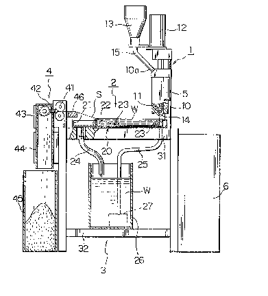
Referring now to FIGS. 1 and 2, there is shown a
synthetic resin pelle-tizing machine according to a first
embodiment of the present invention. The pelletizing machine
is so constructed as -to reduce the overall machine size.
To this end, these parts of the pelletizing machine whi.ch
must be arranged horizontally are minimized to increase those
parts having a vertical construction. A typical example of
-the vertically arranged parts is an extrusion unit 1. As
shown in FIG. 1, the extrusion 1 of the pelletizing machine
comprises an extrusion cylinder 10, an extrusion screw 11,
a driving member 12 for the extrusion screw 11, and a raw
material loading hopper 13. These parts 10 - 13 of the ex-
trusion unit 1 are structurally and functionally simi.lar to
those of the conventional extrusion unit. The extrusion unit
1 of this embodiment differs from the conventional one in
that the extrusion unit 1 as a whole is disposed vertically
As a result, the driving member 12 is disposed directly above
the extrusion cylinder 10, a die head 14 is attached to a lower
end of the extrusion cylinder 10~ and the raw material load-
ing hopper 13 is disposed parallel to the extrusion cylinder
10 via a raw ma-terial feed pipe 15 which extends obliquely
and upwardly from a raw material inlet lOa of the extrusion
cylinder 10. The feed pipe 15 defines therein a raw material
feed passage. In the illustrated embodimen-t, the extrusion
unit 1 is upright. However, it is possible to dispose the
- 2 ~
extrusion unit 1 obliquely at an angle ~ to a horizon-tal
plane, the angle ~ being in the range of 0 to 90 . Taking
the efficient use of the space and the function of the ex-
trusion unit 1 into account, the angle ~ is preferably in
the range of 45- to 90 .
The pelletizing machine further includes a cooling
unit 2 disposed directly below the die head 14. The cooling
unit 2, as clearly shown in FIGSo 1 and 2, is composed of a
double cooling bath 20 which includes a rectangular first
cooling bath 21 and a rectangular second cooling ba-th 22
received in the first cooling bath 21. A pair of freely
rotatable, grooved guide rollers 23, 23 are disposed in the
second cooling bath 22. The guide rollers 23 are located
respectively adjacent to the front and rear ends (left and
right ends in FIG~ 1) of the second cooling bath 22 so as to
define a main portion of a strand feed path along which a
strand S is advanced. A water discharge pipe 24 is connected
via a discharge hole (not designated) to -the bottom wall of
a front end por-tion (left end portion in FIG~ 1) of the
~irst cooling bath 21. Similarly, a water supply pipe 25 is
connected via a supply hole (shown in FIG. 2 not designated)
to a side wall of a rear end portion (right end portion in
FIG. 1) of the second cooling bath 22. The water supp].y
pipe 25 has a receiving end connected to a feed-water pump
27 (FIG. l). The water discharge pipe 24 has a discharge
~" ~
end which is disposed in a water storage tank 26 as well as
the feed-water pump 27. The water s-torage tank 26 is
disposed below the double cooling ba-th 20 and mounted on a
machine frame 3.
The machine frame 3 is composed of a table having
a top support pla~e 31 and an intermediate support plate 32
The extrusion unit 1 and the double cooling bath 20 are
mounted on the top support plate 31, and the water storage
tank 26 is mounted on the intermediate support plate 32.
According to the first embodiment, a cutting unit 4
is disposed along a fron-t end wall (left end wall in FIG~ 1)
of the machine frame 3 such that the cutting unit 4 is
located substantially at a downstream end of the strand feed
path extending through the cooling unit 2. To facilitate
the reduction of the overall size of the pelletizing machine,
a longitudinal extent of the cutting unit 4 which projects
from the front end of the machine frame 3 is reduced as much
as possible so -tha-t the cutting unit 4 has a horizontally
contracted, vertically elonga-ted construction. As shown in
FI~. 1, a cooperating pair of feed rollers 41 is mounted on
the fron-t end portion of the top support plate 31. A fixed
cutter 42 is disposed adjacent to a strand discharge side
of the feed roller pair 41, and a rotary cut-ter 43 is dis-
posed in confrontation with the fixed cutter 42. The fixed
cutter 42 and the rotary cutter 43 are located in a vertically
extending~ rectangular tube-like discharge chute 44. The
chute 44 has a top lid or cover. A pellet collec-ting case
45 is disposed below -the discharge chute 4ll for receiving
therein granules or pellets produced by cutting the strand
S. A strand guide member 46 formed of an elastic materia],
such as a foamed plastics plate, is disposed immediately
upstream of the feed roller pair 41 for guiding -~he strand
S. The strand guide member 46 also has a function to remove
water which has adhered to the strand S while the strand S
is cooled. In FIG. 1, numeral 5 denotes tie rods and 6 a
control panel.
It is obvious that the struc-ture of the cutting
unit 4 is not restricted to the illustrated embodiment.
Furthermore, the cutting unit 4 may not be continuous with
the front end wall of the machine frame 3. As an alterna-
tive, the cutting uni-t 4 in the foregoing embodiment may be
replaced by a strand case or container for receiving therein
the extruded strand S, in which instance a cutting unit is
provided separately from the machine frame 3.
The synthetic resin pelletizing machine of the
foregoing construction operates as follows. The raw material
loading hopper 13 is charged with a raw material composed
of a synthetic resin and various additives, such as a pig-
ment having a predetermined color and a plastiziging agent,
mixed in prede-termined ratios ~ith the synthetic resin.
." , .
J
The raw material loaded in the raw material loading hopper
13 passes through the raw material feed pipe 15 and then is
supplied obliquely from the raw material inlet lOa in-to the
extrusion cylinder 10 at a predetermined angle to the axis of
the extrusion screw 11 and toward the extrusion direction.
It is to be noted that in the case of the conven-
tional extrusion unit, the raw material is supplied into the
extrusion cylinder at right angles ~o the axis of the extru-
sion cylinder, whereas in the case of -the present invention,
the raw material is supplied obliquely into the extrusion
cyl.inder 10 at a predetermined angle to the longitudinal
axis of the extrusion cylinder 10 and toward the extrusion
direction of the extrusion screw 11. Accordingly, in the
pelleti~ing machine of -the invention, the raw material is
smoothly forced in the ex-trusion direction by the extrusion
screw 11 without clogging at the raw material inlet lOa of
the extrusion cylinder 10. The raw material is melted and
kneaded homogeneously while being advanced in the extrusion
cylinder 10, so that fine granules or pellets formed as a
final product are extremely uniform in quality.
The inside temperature of the extrusion cylinder 10
is properly controlled, so that the raw material supplied in
the extrusion cylinder 10 is plasticated and kneaded as it is
progressively advanced toward the die head 14 by the rota-
tion of the extrusion screw 11. From the die head 1~ which
-1 O-
2 ~ 2 ~ 9
is attached to -the lower end of the extrusion cylinder 10,
the raw material is ex~ruded downwardly in-to the second
cooling bath 22 in the form of the strand S having a
predetermined thickness. In this instance, since the
extrusion direction of the strand S is equal to the direc-
tion of i-ts own weight ac-ting on the strand S, the extruded
strand S, as opposed to the strand formed by the conven-
tional horizontal-type ex-trusion unit, is not subjected
to a lateral bending force and can enter by i-ts own weight
into the second cooling bath 22.
The strand S passes through cooling ~ater W in the
second cooling bath 22 while it is being guided by the
grooved guide rollers 23. The strand S is thus cooled with
water W. Then, the cooled strand S passes through the
strand guide member 46 during which time water adhering to
the surface of the strand S is removed. Subsequently, the
strand S is continuously advanced by the feed roller pair 41
toward the fixed cutter 42 and the rotary cutter 43. Be-
tween the fixed cu-tter 42 and the rotary cutter 43, the
strand S is cut into granules or pellets of a predetermined
size. The pellets thus produced fall within the discharge
chute 44 and then are received in the collecti.ng case 45
disposed below the discharge chu-te 44.
In the cooling unit 2, the feed-water pump 27 dis-
posed in the water storage tank 26 feeds cooling water W
2:12~Q~
from the storage tank 26 -through the ~a-ter supply pipe 25
to the second cooling bath 22. The cooling water W then
overflo~s from the second cooling bath 22 into -the first
cooling bath 21 from which the cooling water W is discharged
via the water discharge pipe 24 into the water storage -tank
26 where the cooling water W is stored. With this circ-ulation,
the cooling water W is used efficiently.
FIG. 3 illustrates a second embodiment of the
present invention. In this embodiment, the extrusion cylin-
der 10 is disposed obliquely at an angle of about 45 5 and
the raw material loading hopper 13 and the ra~ material
supply pipe 15 are disposed vertically. Also in this embod-
iment, the raw material supply pipe 15 is cormected with the
extrusion cylinder 10 in a crossing manner at an angle of
about l~5 . Similarly, the die head 14 faces obliquely at
the same angle (viz., 45 ) to the cooling unit 2, so that
the extruded strand S enters obliquely into the second
cooling ba-th 22. In this instance, the strand S is subject-
ed to a force tending to bend the strand S. However, the
bending force is considerably smaller than that produced in
the case of the conventional horizontal~type extrusion unit
and can only exert negligible influence on the quality of
the strand S. Other structural and functional details of
the second embodiment are substantially the same as those
of the first embodiment previously mentioned.
- 1 2 -
2~2~
The present invention thus constructed makes it
possible to reduce the overall size of the pelletizing
machine and hence use the space efficiently on condition
that the pelletizing machine has the same production capaci-
ty as the conventional pelletizing machine. In particular,
the extrusion unit 1 is of -the vertical type so that when
the overall size of the pelletizing machine is reduced to
cope with the multi-product, small-quantity production
system, various main-tenance works can be achieved easily.
As is apparent from the foregoing description, the
synthetic resin pelle-tizing machine of the present invention
is compact as a whole and, hence, is able to use the space
efficien-tly. In addition, the pelle-tizing machine can respond
to the need for downsizing, is able to obviate the need for
troublesome maintenance even though a vertical-type extrusion
unit is used, and is adaptable to ~he multi-produc-t, small-
quantity production sys-tem. The vertical-type extrusion
unit provides a smooth extrusion mechanism for a melted
resin. More specifically, since the raw material is supplied
obliquely into the extrusion cylinder and toward -the extru-
sion direction, the raw material is smoothly advanced by the
e~trusion screw wi-thou-t clogging at the inlet of the extrusion
cylinder. The raw material while being advanced in the
extrusion cylinder is plasticated and kneaded homogeneously.
The strand extruded from the die head reaches the cooling
- 1 3 -
~: . .
~ A
2~2~ n~s
unit by its own weight, so that an extruded, incompletely
solidified strand is not subjected to undue bending forces.
Thus, pellets produced from the strand has high dimensional
accuracy.
Obviously, various minor changes and modifications
of the present invention are possible in the light of the
above teaching It is therefore to be understood that
within the scope of the appended claims the invention may
be practiced other~ise than as specifically described.