Sélection de la langue

Search

Sommaire du brevet 2121882 

Énoncé de désistement de responsabilité concernant l'information provenant de tiers

Une partie des informations de ce site Web a été fournie par des sources externes. Le gouvernement du Canada n'assume aucune responsabilité concernant la précision, l'actualité ou la fiabilité des informations fournies par les sources externes. Les utilisateurs qui désirent employer cette information devraient consulter directement la source des informations. Le contenu fourni par les sources externes n'est pas assujetti aux exigences sur les langues officielles, la protection des renseignements personnels et l'accessibilité.

Disponibilité de l'Abrégé et des Revendications

L'apparition de différences dans le texte et l'image des Revendications et de l'Abrégé dépend du moment auquel le document est publié. Les textes des Revendications et de l'Abrégé sont affichés :

  • lorsque la demande peut être examinée par le public;
  • lorsque le brevet est émis (délivrance).
(12) Demande de brevet: (11) CA 2121882
(54) Titre français: SYSTEME DE GUIDAGE A DEUX CLOUS SERVANT A ALIGNER LES CLOUS D'INTERVERROUILLAGE SUR LES PERFORATIONS DANS LA PARTIE DISTALE
(54) Titre anglais: DOUBLE NAIL GUIDING SYSTEM FOR TARGETING OF DISTAL SCREW HOLES OF INTERLOCKING NAILS
Statut: Réputée abandonnée et au-delà du délai pour le rétablissement - en attente de la réponse à l’avis de communication rejetée
Données bibliographiques
Abrégés

Abrégé anglais


A double nail guiding system for stabilizing broken
bones includes a twin jig, first and second interlocking nails
extending from the twin jig, wherein each interlocking nail
defines a channel along a longitudinal axis thereof. The
interlocking nails also include a distal portion which includes
at least one hole. A centric or eccentric guiding pipe,
including a channel in the center, extends through the first
interlocking nail in a direction toward the second interlocking
nail. A K-wire is inserted into the channel in the guiding pipe,
such that the K-wire extends through the guiding pipe and through
the hole defined in the second interlocking nail which is in the
bone being stabilized. A guide probe is inserted into the
channel in the second interlocking nail (which is in the bone)
toward the distal portion thereof. In this manner, alignment of
the hole in the distal portion of the first interlocking nail and
the hole in the distal portion of the second interlocking nail is
confirmed by contacting the guide probe with the K-wire.
Advantageously, the first interlocking nail and the second
interlocking nail are constructed to be of equal length and equal
size. The procedures of distal locking screw targeting were simplified
with an 100% successful rate. The radiation exposure to the patient
and the surgeon's hand is no longer necessary during the distal
locking of femur.

Revendications

Note : Les revendications sont présentées dans la langue officielle dans laquelle elles ont été soumises.


THE EMBODIMENTS OF THE INVENTION IN WHICH AN EXCLUSIVE PROPERTY
OR PRIVILEGE IS CLAIMED ARE DEFINED AS FOLLOWS:
1. A double nail guiding system, comprising:
a twin jig;
a first interlocking nail extending from the twin
jig, wherein the first interlocking nail defines a channel along
a longitudinal axis thereof, the first interlocking nail
including a distal portion which includes at least one hole
defined therein;
a second interlocking nail extending from the twin
jig, wherein the second interlocking nail defines a channel along
a longitudinal axis thereof, the second interlocking nail
including a distal portion which includes at least one hole
defined therein;
a centric or eccentric guiding pipe defining a
channel therethrough, the guiding pipe adapted to extend through
the first interlocking nail in a direction toward the second
interlocking nail;
a K-wire adapted to be inserted into the channel
defined in the guiding pipe, the K-wire adapted to extend through
the guiding pipe and through the hole defined in the second
interlocking nail; and
a guide probe adapted to be inserted into the
channel defined in the second interlocking nail toward the distal
portion thereof, wherein alignment of the hole in the distal
portion of the first interlocking nail and the hole in the distal

portion of the second interlocking nail is confirmed by
contacting the guide probe with the K-wire.
2. The double nail guiding system according to claim
1, wherein the first interlocking nail and the second
interlocking nail are of equal length.
3. The double nail guiding system according to claim
1, wherein the first interlocking nail and the second
interlocking nail are of equal size.
4. The double nail guiding system according to claim
1, further comprising holding screws for connecting the first
interlocking nail and the second interlocking nail to the twin
jig.
5. The double nail guiding system according to claim
1, wherein two holes are defined in the distal portion of the
first interlocking nail, and two holes are defined in the distal
portion of the second interlocking nail.
6. A double nail guiding system, comprising:
a twin jig;
a first interlocking nail extending from the twin
jig, wherein the first interlocking nail defines a channel along
a longitudinal axis thereof, the first interlocking nail
including a distal portion which includes at least one hole
defined therein;
a second interlocking nail extending from the twin
jig, wherein the second interlocking nail defines a channel along
a longitudinal axis thereof, the second interlocking nail

including a distal portion which includes at least one hole
defined therein;
wherein the first interlocking nail and the second
interlocking nail are of equal length and size such that when a
broken bone is being treated on the right side of a body, the
first interlocking nail is used as a true nail and the second
interlocking nail is used as a guide nail, and when a broken bone
is being treated on the left side of the body, the first
interlocking nail is used as the guide nail and the second
interlocking nail is used as the true nail.
7. The double nail guiding system according to claim
6, further including a centric or eccentric guiding pipe defining
a channel therethrough, the guiding pipe adapted to extend
through the guide nail in a direction toward the true nail.
8. The double nail guiding system according to claim
7, further including a K-wire adapted to be inserted into the
channel defined in the guiding pipe and extending through the
guiding pipe and through the hole in the true nail.
9. The double nail guiding system according to claim
8, further including a guide probe adapted to be inserted into
the channel defined in the true nail toward the distal portion
thereof, wherein alignment of the hole in the true nail and the
hole in the guide nail is confirmed by contacting the guide probe
with the K-wire.
10. The double nail guiding system according to claim
6, further including holding screws for connecting the first

interlocking nail and the second interlocking nail to the twin
jig.
11. The double nail guiding system according to claim
6, wherein two holes are defined in the distal portion of the
first interlocking nail, and two holes are defined in the distal
portion of the second interlocking nail.

Description

Note : Les descriptions sont présentées dans la langue officielle dans laquelle elles ont été soumises.

-- 2121882
A DC~rBLE NAIL GUIDING SYSTE2l FOR TARGETING
OF DI~TAI, 8CREW HOLES OF Illq~ERLOC~ING N~ILS
BACKGROUND OF THE INVENTION
s Successful placement of the distal screws into a tibial
and femoral interlocking nail without roentgenogram assistance is
a technically demanding procedure, because the accuracy of the
targeting device included in the original nail Ino~nted svstems
requires a time wasting and inaccurate m~thod. Furthermore,
the most commonly used t~chnigue for distal interlocking screw
placoment is the freehand method. ~owever, the fr~e~And method stil7
includes the drawbacks of time expenditure and radiation exposu~e-
Therefore, it is an object of the present invention toprovide a new guiding system which may obviate and mitigate the
above-mentioned drawbacks.
SUMMARY OF THE INVENTION
This invention relates to a double nail guiding system.
It is the primary object of the present invention to
provide a double nail guiding system which includes a combination
of two interlocking nails of equal length and/or e~ual size for the
distal screw targeting procedure.
It is another object of the present invention to
provide a double nail guiding system which is simple in
structure.
It is still another object of the present invention to
provide a double nail guiding system which is easy to adjust
during the operation.

-- 2121882
It is still another object of the present invention to
provide a double nail guiding system which is economical to
produce.
It is still another object of the present invention to
provide a double nail guiding system which is accurate during the
operation.
It is still another object of the present invention to
provide a double nail guiding system which markedly saves
operation time.
It is still another object of the present invention to
provide a double nail guiding system which is radiation-free in
the process of targeting the distal interlocking screws during
the operation.
It is a further object of the present invention to
provide a double nail guiding system which can be used for a long
time.
Other objects and merits and a fuller underst~n~ing of
the present invention will be obtained by those having ordinary
skill in the art when the following detailed description of the
preferred embodiment is read in conjunction with the accompanying
drawings.
BRIEF DESCRIPTION OF THE DRAWINGS
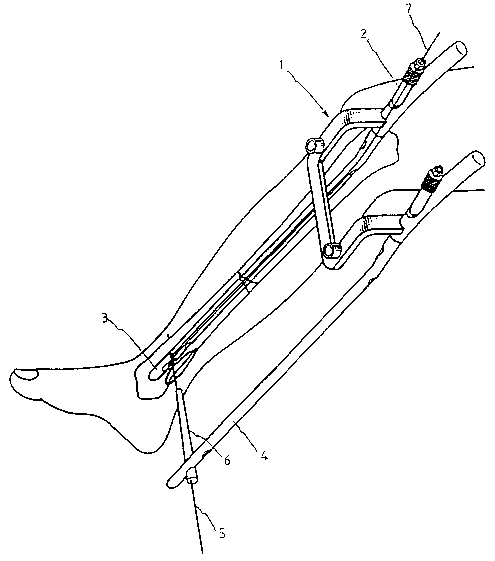
FIG. 1 is a perspective view of a double nail guiding
system for targeting of distal screw holes of the tibia
interlocking nail according to the present invention;

- 2121882
- FIG. 2 is a perspective view showing the application of
the double nail guiding system in the tibia for targeting the
most distal interlocking screw hole;
FIG. 3 shows the application of a drill in the most
distal screw hole of the double nail guiding system in the tibia;
FIG. 4 shows a view illustrating the driving of the
transfixing interlocking screw into the most distal screw hole of
the double nail guiding system in the tibia;
FIG. 5 is an exploded view of a double nail guiding
system for targeting of a distal screw hole of the femoral
interlocking nail according to the present invention;
FIG. 6 is a perspective view showing the application of
the double nail guiding system in the femur for targeting the
most distal interlocking screw hole;
FIG. 7 shows the application of a drill in the most
distal screw hole of the double nail guiding system in the femur;
and
FIG. 8 shows a view illustrating the driving of the
transfixing interlocking screw into the most distal screw hole of
the double nail guiding system in the femur.
DETATT.T~n DESCRIPTION OF THE PREFERRED EMBODIMENT
With reference to the drawings, and in particular to
FIG. 1 thereof, the double nail guiding system in accordance with
the invention includes a tibial twin jig (1) which may be
connected to two nails (3,4) of equal length with two separate

21~1~82
(~olding screws (2). The nail that will be driven into the
fractured tibia is called the "true nail". The other nail at the
medial border of the leg is called the "guiding nail" based on
its use as a guide. For example, in right tibia unstable
fractures, the left side interlocking nail (3) of this
combination is the true nail which will be inserted into the
fractured tibia. The right side nail (4) on the medial side of
the leg acts as a guiding nail. Alternatively, in left tibia
unstable fractures, the right side nail (4) acts as the true
nail, and the left side nail (3) acts as the guiding nail.
As shown in FIG. 2, using the double nail guiding
system in accordance with the invention, a K-wire (5) and an
eccentric guiding pipe (6) are used in targeting the most distal
screw hole of the true nail (3) inside the tibia. Due to the
fact that the position of the distal screw holes of the tibia
interlocking nail may include errors as a result of
manufacturing, sets of centric and eccentric pipes are designed
to correct these intrinsic errors.
Additionally, a guiding probe (7) is put into the true
nail (3) from the proximal end to the distal end to make sure
that the K-wire (5) is transfixing through the most distal screw
hole of the true nail (3). A metallic sound may be heard when
the guiding probe (7) hits the K-wire (5). Thereafter, the K-
wire (5) and the guiding pipe (6) are removed.
FIG. 3 shows a drill (8) going through the K-wire (5)
pre-drilled cortices. The guiding probe (7) may be used again to
-- 4 --

2121882
nake sure that the drill (8) is transfixing the true nail (3~.
Thereafter, the drill (8) and the guiding nail (4) are removed.
FIG. 4 shows a screw (9) being driven into the true
nail (3). The guiding probe (7) may be used to make sure that
the screw (9) is driven at the proper location. No radiation
exposure is n~cess~ry.
The targeting of the second distal interlocking screw
hole of the tibia interlocking nail is performed following the
same procedures described above.
FIG. S illustrates an exploded view of a femoral twin
jig (10) according to the present invention. The femoral twin
jig (10) may be connected to two nails (11,12) of equal length
with two separate holding screws (2). The nail that will be put
into the fractured femur is called the "true nail". The other
nail at the lateral border of the thigh is called the "guiding
nail" h~e~ on its use as a guide. For example, in right femoral
unstable fractures, the left side interlocking nail (11) of this
combination is the true nail which will be inserted into the
fractured femur. The right side nail (12) on the lateral side of
the leg acts as the guiding nail. In left femoral unstable
fractures, the left side nail (11) still acts as the true nail
and the right side nail (12) acts as the guiding nail. Due to
the fact that the position of the distal screw holes of the
femoral interlocking nail may include errors as a result of
manufacturing, sets of eccentric pipes are designed to correct
these intrinsic errors.

212188~
_ As shown in FIG. 6, using the double nail guiding
system in accordance with the invention, a K-wire (5) and an
eccentric guiding pipe (6) are used to target the most distal
screw hole of the true nail (11) inside the femur. Additionally,
a guiding probe (7) is put into the true nail (11) from the
proximal end to the distal end to make sure that the K-wire (5)
is transfixing through the most distal screw hole of the true
nail (11). A metallic sound may be heard when the guiding probe
(7) hits the K-wire (S). Thereafter, the K-wire (5) and guiding
pipe (6) are removed.
FIG. 7 shows a drill (8) going through the K-wire (5)
pre-drilled cortices. The guiding probe (7) may be used again to
make sure that the drill (8) is transfixing the true nail.
Thereafter, the drill (8) and guiding nail (12) are removed.
FIG. 8 shows a screw (9) being driven into the true
nail (ll). The guiding probe (7) may be used to make sure that
the screw (9) is driven at the proper location. No radiation
exposure is necess~ry.
The targeting of the second distal interlocking screw
hole of the femur interlocking nail is performed following the
same procedures described above.
It should be noted, however, that the present invention
(system) may be used for targeting different types of
interlocking nails.

2121882
- The interlocking nails in accordance with the invention
may be used for long bone fractures, such as tibia, femur,
humerus, radius, ulna, metacarpal and metatarsal fractures etc.
The application of the present invention is too wide to
be mentioned and cannot be all enumerated here in detail It is
understood that the present disclosure is made by way of example
only, and that numerous changes in the detail of the construction
and combination of parts may ~e resorted to without departing
from the spirit and scope of the invention as hereinafter
claimed.

Dessin représentatif
Une figure unique qui représente un dessin illustrant l'invention.
États administratifs

2024-08-01 : Dans le cadre de la transition vers les Brevets de nouvelle génération (BNG), la base de données sur les brevets canadiens (BDBC) contient désormais un Historique d'événement plus détaillé, qui reproduit le Journal des événements de notre nouvelle solution interne.

Veuillez noter que les événements débutant par « Inactive : » se réfèrent à des événements qui ne sont plus utilisés dans notre nouvelle solution interne.

Pour une meilleure compréhension de l'état de la demande ou brevet qui figure sur cette page, la rubrique Mise en garde , et les descriptions de Brevet , Historique d'événement , Taxes périodiques et Historique des paiements devraient être consultées.

Historique d'événement

Description Date
Inactive : CIB de MCD 2006-03-11
Le délai pour l'annulation est expiré 1998-04-21
Demande non rétablie avant l'échéance 1998-04-21
Réputée abandonnée - omission de répondre à un avis sur les taxes pour le maintien en état 1997-04-21
Demande publiée (accessible au public) 1995-10-22

Historique d'abandonnement

Date d'abandonnement Raison Date de rétablissement
1997-04-21
Titulaires au dossier

Les titulaires actuels et antérieures au dossier sont affichés en ordre alphabétique.

Titulaires actuels au dossier
CHI-YUAN HWANG
Titulaires antérieures au dossier
S.O.
Les propriétaires antérieurs qui ne figurent pas dans la liste des « Propriétaires au dossier » apparaîtront dans d'autres documents au dossier.
Documents

Pour visionner les fichiers sélectionnés, entrer le code reCAPTCHA :


Pour visualiser une image, cliquer sur un lien dans la colonne description du document. Pour télécharger l'image (les images), cliquer l'une ou plusieurs cases à cocher dans la première colonne et ensuite cliquer sur le bouton "Télécharger sélection en format PDF (archive Zip)" ou le bouton "Télécharger sélection (en un fichier PDF fusionné)".

Liste des documents de brevet publiés et non publiés sur la BDBC .

Si vous avez des difficultés à accéder au contenu, veuillez communiquer avec le Centre de services à la clientèle au 1-866-997-1936, ou envoyer un courriel au Centre de service à la clientèle de l'OPIC.


Description du
Document 
Date
(aaaa-mm-jj) 
Nombre de pages   Taille de l'image (Ko) 
Description 1995-10-22 7 237
Page couverture 1995-12-05 1 14
Abrégé 1995-10-22 1 39
Dessins 1995-10-22 8 112
Revendications 1995-10-22 4 119
Dessin représentatif 1998-05-22 1 13
Taxes 1996-04-26 1 47