Sélection de la langue

Search

Sommaire du brevet 2122250 

Énoncé de désistement de responsabilité concernant l'information provenant de tiers

Une partie des informations de ce site Web a été fournie par des sources externes. Le gouvernement du Canada n'assume aucune responsabilité concernant la précision, l'actualité ou la fiabilité des informations fournies par les sources externes. Les utilisateurs qui désirent employer cette information devraient consulter directement la source des informations. Le contenu fourni par les sources externes n'est pas assujetti aux exigences sur les langues officielles, la protection des renseignements personnels et l'accessibilité.

Disponibilité de l'Abrégé et des Revendications

L'apparition de différences dans le texte et l'image des Revendications et de l'Abrégé dépend du moment auquel le document est publié. Les textes des Revendications et de l'Abrégé sont affichés :

  • lorsque la demande peut être examinée par le public;
  • lorsque le brevet est émis (délivrance).
(12) Brevet: (11) CA 2122250
(54) Titre français: METHODE ET DISPOSITIF D'ESSAI DE RECIPIENTS
(54) Titre anglais: METHOD FOR TESTING CONTAINERS, USE OF THE METHOD, AND A TESTING DEVICE
Statut: Périmé et au-delà du délai pour l’annulation
Données bibliographiques
Abrégés

Abrégé anglais


The invention concerns a method and device for
testing containers, the method calling for a difference in
pressure to be generated between the pressure inside the
container and the pressure immediately surrounding the
container, the behaviour of one of these pressures permitting
the gastightness of the container to be assessed. A pressure
value is stored and subsequently compared with one of the
pressures, the stored pressure value being stored
electronically and compared with at least one value of the
output signal from a pressure sensor. The container is
housed in an enclosure which is connected to a pressure or
suction line, and a pressure-value storage unit, a comparator
unit and a pressure sensor are associated with the pressure
or suction line.

Revendications

Note : Les revendications sont présentées dans la langue officielle dans laquelle elles ont été soumises.


11
Claims:
1. A method for manufacturing a container which is
tested on predetermined test conditions, in which the
container is construed and a pressure difference is created
between a pressure inside the container and a pressure in
its environment, and from the behavior of one of the
pressures it is established whether the container satisfies
predetermined test conditions, wherein, after said one of
the pressures reaches a predetermined test value as said
pressure difference is being created and after creation of
said pressure differences, in an equalization phase said one
of said pressures rereaches said predetermined test value,
the change in pressure of said one of the pressures is
measured with a pressure sensor and with respect to said
predetermined test value immediately after the time at which
said one of said pressures rereaches said predetermined test
value and utilizing results of said measuring for
establishing whether the container satisfies said
predetermined test conditions.
2. Method according to claim 1, wherein the test
pressure value is stored electronically and subsequently the
stored value is compared to at least one value of an output
signal of said pressure sensor.
3. Method according to claim 2, wherein the storage is
accomplished at least in part by means of an analog/digital
converter that is enabled at a predetermined time at which
said one of the pressures rereaches said predetermined test
value to perform conversion.
4. Method according to claim 1, wherein an electrical
output signal of the sensor is compared to one or more
predetermined values.
5. Method according to claim 1, wherein a value of an
output signal of said sensor is stored as a pressure value.

12
6. Method according to claim 1, wherein the pressure in
the interior of the container is increased or decreased and a
value of the pressure of the interior of the container is
measured.
7. Method according to claim 1, wherein the pressure in
the interior of the container is increased or decreased and a
value of the pressure of the environment of the container is
measured.
8. Method according to claim 1, wherein the pressure in
the environment of the container is increased or decreased
and a value of the pressure of the interior of the container
is measured.
9. Method according to claim 1, wherein the pressure in
the environment of the container is increased or decreased
and a value of the pressure of the environment of the
container is measured.
10. Method according to claim 1, wherein an amplifier
element is located in series with said pressure sensor, an
output signal of said amplifier element being used before the
comparison is made, as a null-balance signal.
11. Method according to claim 1, wherein said utilizing
involves testing the gas tightness of the containers.
12. Method according to claim 1, wherein said utilizing
involves testing the volume of the container.
13. Method according to claim 1, wherein said pressure
sensor provides an output signal, the change in said output
signal over a measuring time interval t1 to t2 being used to
provide an indication of said change in pressure of said one
of the pressures.
14. Method according to claim 13, wherein said step of
utilizing results of said measuring includes comparing said
indication of said change in pressure of said one of the
pressures with a predetermined nominal value therefor to

13
establish whether the container satisfies predetermined test
conditions.
15. Test arrangement for testing containers, said
arrangement comprising a pressure or suction source, which
can be effectively connected to a container to be tested with
respect to its interior and exterior pressure for creating a
pressure difference between said interior and exterior
pressures, at least one pressure sensor, an electronic
pressure-value storage arrangement and a comparator unit,
wherein the pressure sensor is a converter that converts an
input-side pressure value into an output-side electrical
signal, and means for feeding the output of the sensor, on
the one hand, and the output of said electronic pressure-
value storage arrangement, on the other to said comparator
unit to commence a measuring test interval at a point in time
immediately after the input-side pressure value of said
sensor reaches a predetermined test value as said pressure
difference is being created and after creation of said
pressure difference, in an equalization phase said one of
said pressures rereaches said predetermined test value.
16. Arrangement according to claim 15, wherein, to test
for leaks, means are provided to feed the output of the
sensor to the input of the electronic pressure-value storage
arrangement.
17. Arrangement according to claim 15, further
comprising a container connection, which can be sealed to a
container opening, said container connection being equipped
with an input for said sensor and a source connection.
18. Arrangement according to claim 15, further
comprising a container connection equipped with an input for
said sensor which can be sealed to a container opening and a
sealable chamber to receive a container, into which said
source empties.

14
19. Arrangement according to claim 15, further comprising
a container connection equipped with a source connection, that
can be sealed to an opening of the container and a sealable
chamber to receive the container at or in which a sensor input
is provided.
20. Arrangement according to claim 15, wherein a sealable
chamber to receive the container is provided.
21. Arrangement according to claim 15, wherein the
pressure-value storage arrangement is a pair of
analog/digital//digital/analog converters connected one after
the other.
22. Arrangement according to claim 15, wherein an
amplifier is placed after the sensor output; and means are
provided for storing the output signal of said amplifier in a
controlled manner and, once stored, for acting on the input
signal of the amplifier as a null-balance signal.
23. Arrangement according to claim 15, wherein, to test
volume said electronic pressure-value storage arrangement
comprises a storage unit that can be set externally.
24. A method for manufacturing a tight container
comprising:
construing a container with a wall;
establishing a differential pressure between a first
pressure in an interior of said container along an inside of
the wall, and a second pressure along an outside of the wall;
monitoring at least one of said first and second
pressures and generating an electrical monitoring output
signal;
storing said electrical output signal at a first moment
to generate a stored signal;
comparing said electrical output signal at a second
deferred moment with said stored signal and concluding from a
result signal of said comparing, whether said container is
tight or not;

15
further comparing said stored signal with said electric
output signal at said first moment, the result signal of said
further comparing being exploited as a zero offset signal.
25. The method of claim 24, further comprising the step
of comparing said result signal of said comparing with one or
more than one predetermined values.
26. The method of claim 24, wherein said differential
pressure is established by increasing or reducing said first
pressure, thereby monitoring of said second pressure.
27. The method of claim 24, wherein said differential
pressure is established by increasing or reducing said second
pressure, thereby monitoring said first pressure.
28. The method of claim 24, further comprising
establishing said pressure difference by increasing or
reducing said second pressure, thereby monitoring said second
pressure.
29. The method of claim 24, wherein establishing said
differential pressure is performed by increasing or reducing
said first pressure, thereby monitoring said first pressure.
30. The method of claim 24, wherein said storing
comprises analog to digital converting said electrical output
signal at said first moment.
31. The method of claim 30, further comprising digital
to analog reconverting said analog to digital converted
output signal.
32. The method of claim 24, further comprising storing
said result signal of said further comparing.
33. The method of claim 32, further comprising
superimposing said stored result signal of said further
comparing to said result signal.
34. The method of claim 24, further comprising
performing said storing delayed by a predetermined time
period with respect to terminating establishing said
differential pressure.

16
35. The method of claim 24, further comprising varying at
least one of said first and second pressures for establishing
said differential pressure increasingly, stopping said varying
and performing said storing after said differential pressure
established starts to decrease.
36. The method of claim 35, further comprising the step
of detecting said differential pressure being decreasing by
detecting when said differential pressure rereaches a value,
which was already reached by said increasing differential
pressure.
37. A test arrangement for containers comprising a
pressure or suction source operationally connected to the
inside of a container to be tested or to a sealed cavity
wherein said container resides and at least one pressure
sensor, the input thereof being operationally connected to
said inside of said container or to said sealed cavity outside
said container and generating an electrical output signal at
its output, the output of said pressure sensor being
operatively connected to the input of a storage unit having an
output, the output of said storage unit and the output of said
sensor being operatively connected to inputs of a comparing
unit, the output of said comparing unit being operatively
connected to a further storage unit, the output of said
further storage unit being operatively connected to a zero
offset adjusting input of the arrangement.
38. The test arrangement of claim 37, further comprising
an input of said sensor, said input of said sensor and said
source being removably applicable to an opening of a
container.
39. The arrangement of claim 37, further comprising a
test chamber sealingly closable for receiving a container to
be tested.

17
40. The arrangement of claim 39, said sensor comprising
an input applicable to the inside of the container in said
chamber, said source being connected to said chamber.
41. The arrangement of claim 39, said sensor comprising
an input connected to said chamber, said source being
connected to said chamber.
42. The arrangement of claim 39, wherein said sensor
comprises an input connected to said chamber and said source
is applicable to an opening of a container in said chamber.
43. The arrangement of claim 37, said storage unit
comprising an analog to digital converter, the analog input of
said converter being operatively connected to the output of
said sensor.
44. The arrangement of claim 43, the digital output of
said analog to digital converter being operatively connected
to a digital input of a digital to analog converter, the
analog output of said digital to analog converter being
operatively connected to said comparing unit.
45. The arrangement of claim 37, wherein the output of
said further storage unit is operatively connected to an input
of an amplifier unit.
46. The arrangement of claim 37, further comprising a
control unit, said control unit enabling said storage unit and
said further storage unit substantially simultaneously.
47. A method for manufacturing containers which are
tested on predetermined leak conditions, in which there is
generated a leak indicative output signal of a sensor and from
the behavior of said output signal it is established whether
the container satisfies predetermined leak test conditions,
comprising the steps of:
storing said output signal at a first moment to generate
a stored signal;
comparing said output signal at a second deferred moment
with said stored signal and concluding from a result signal of

18
said comparing, whether said container fulfills said leak
condition; and
further comparing said stored signal with said output
signal at said first moment, the result signal of said further
comparing being exploited as a zero offset signal.

Description

Note : Les descriptions sont présentées dans la langue officielle dans laquelle elles ont été soumises.


CA 02122250 2003-09-08
1
METHOD FOR TESTING CONTAINERS, USE OF THE METHOD,
AND A TESTING DEVICE
This invention pertains to a method for manufacturing
tight containers and a testing device and arrangement for
testing containers.
This invention pertains to a testing device such as is
known from US-PS 5,029,464 and EP-A-O 313 678 and
EP-A-O 432 143.
From these items a way is known that a pressure
differential is to be created between a pressure in the
interior of the container and a pressure in said container's
environment in order to test the gas tightness of containers
and, from the behavior of one of the pressures, it is to be
established whether the container under test satisfies the
gas-tightness conditions or volume conditions or not.
In this process the container to be tested is placed in
a sealing chamber that is connected to a pressure medium
source or a suction source; said arrangement is_to be used to
create the above-mentioned pressure differential. After the
pressure differential is created, a pressure value for the
environment of the container is stored as a starting
condition in a reference pressure chamber, which is placed in
front of a pressure differential sensor, and is compared with
subsequent pressure values for the environment of the
container.
The above-mentioned documents are thus declared to be an
integral part of the present description.
A drawback to the known method is the fact that a
pressure differential sensor with extremely accurate control
valves must be provided to ensure that even very small leaks
or slight deviations of the container volume from a nominal
volume are detected.

CA 02122250 2003-09-08
2
The goal set for the present invention is to simplify
this known method significantly. The present invention
accordingly provides a method for manufacturing containers
which are tested on predetermined test conditions, in which
containers are construed and a pressure difference is created
between a pressure inside the container and a pressure in its
environment, and from the behavior of one of the pressures it
is established whether the container satisfies predetermined
test conditions, wherein, after said one of the pressures
reaches a predetermined test value as said pressure
difference is being created and after creation of said
pressure differences, in an equalization phase said one of
said pressures rereaches said predetermined test value, the
change in pressure of said one of the pressures is measured
with a pressure sensor and with respect to said predetermined
test value immediately after the time at which said one of
said pressures rereaches said predetermined test value and
utilizing results of said measuring for establishing whether
the container satisfies said predetermined test conditions.
The present invention also provides a test arrangement
for testing containers, said arrangement comprising a
pressure or suction source, which can be effectively
connected to a container to be tested with respect to its
interior and exterior pressure for creating a pressure
difference between said interior and exterior pressures, at
least one pressure sensor, an electronic pressure-value
storage arrangement and a comparator unit, wherein the
pressure sensor is a converter that converts an input-side
pressure value into an output-side electrical signal, and
means for feeding the output of the sensor, on the one hand,
and the output of said electronic pressure-value storage
arrangement, on the other to said comparator unit to commence
a measuring test interval at a point in time immediately
after the input-side pressure value of said sensor reaches a

CA 02122250 2003-09-08
3
predetermined test value as said pressure difference is being
created and after creation of said pressure difference, in an
equalization phase said one of said pressures rereaches said
predetermined test value.
The present invention further provides a method for
manufacturing a tight container comprising: construing a
container; establishing a differential pressure between a
first pressure in the interior of said container and a second
pressure in the vicinity of said container; monitoring at
least one of said first and second pressures and generating
an electrical monitoring output signal; storing said
electrical output signal at a first moment to generate a
stored signal; comparing said electrical output signal at a
second deferred moment with said stored signal and concluding
from a result signal of said comparing, whether said
container is tight or not; further comparing said stored
signal with said electric output signal at said first moment,
the result signal of said further comparing being exploited
as a zero offset signal.
Accordingly, a pressure differential sensor is no longer
used, nor are pneumatic storage chambers; instead, the
pressure that is of interest is determined by means of a
relative-pressure sensor and converted into an electrical
signal; when checking for leaks, this signal is stored at a
predetermined time and compared with at least one subsequent
value that is determined by this same sensor. When checking
volume, a pressure value is pre-specified and stored as a
basis for comparison. This obviates the need for awkward
devices of the previously known type, namely the pressure
differential sensor and, in particular, the stop valves that
are quite difficult as regards control characteristics.
The method of the invention is implemented in a
configuration wherein an electrical output signal of the
sensor is compared to one or more predetermined values, e.g.,

CA 02122250 2003-09-08
4
on a computer into which the sensor output is entered. A
value of the sensor output signal is stored as a pressure
value. Either the pressure in the interior of the container
or that in the environment of the container is increased or
decreased, and a value of the pressure in the container or in
the environment of the container is measured.
In a preferred embodiment, both the source connection to
admit the pressure medium or to ensure suction and the sensor
input are hooked up to either the interior of the container
or the container's environment.
The creation of the pressure differential can be done in
different ways, with which the specialist is well acquainted
from the above-mentioned documents. Thus, for example, the
pressure differential can be created by carrying out
pressurization or suction at a predetermined level for a
predetermined time, and then analyzing both a pressure value
that is reached and its plot. In addition, pressurization
can be done to a predetermined pressure differential, and
then the plot of the pressure value that is of interest can
be observed.
As is known from the above-mentioned documents,
pressurization can also be accomplished by precharging a pre-
chamber to a predetermined pressure and then discharging said
chamber into the container or into an enclosure that is
formed by a sealable chamber.
When checking volume, a volume that is dependent on the
volume of the container, either the interior volume of said
container itself or its volume differential compared to a
testing chamber, can be pressurized by a predetermined
quantity of pressure medium, or a predetermined amount of gas
can be removed from this volume. The volume of the container
is then determined from the resulting pressure.

CA 02122250 2003-09-08
4a
Of course, the values that are measured are compared
with nominal values or nominal plots, as is also known from
the above-mentioned documents.
Storage, wherein the pressure in the environment of the
container is increased or decreased and a value of the
pressure of the environment of the container is measured, is
preferably undertaken in such a way that, with control at a
predetermined time, an analog/digital converter is enabled to
convert the sensor output signal, and the then stationary
output signal of this analog/digital converter is used as a
reference value for the subsequent analysis of the sensor
output signal. In this process, either another
analog/digital converter can be installed behind the sensor
output and the output signal of the latter converter can then
be digitally compared to that of the storage unit A/D
converter or, preferably, a D/A converter is placed
immediately behind the storage A/D converter and thus the
stored, re-converted signal is fed as an analog reference
signal to an analog comparator unit, to which the output
signal of the sensor is also fed directly.
In addition, and wherein the pressure in the environment
of the container is increased or decreased and a value of the
pressure of the environment is measured, a null balance is
preferably undertaken by determining, essentially during the
value storage process at the comparator, whether an output
signal of the device encompasses the null value, at least
approximately; if a signal appears that deviates from the
null value or from a predetermined minimum value, then said
signal is used as a null-balance signal.
Preferred embodiments of the test arrangement of the
invention for testing containers comprise a pressure or
suction source which can be effectively connected to a
container to be tested with respect to its interior and
exterior pressure, at least one pressure sensor, an

CA 02122250 2003-09-08
4b
electronic pressure-value storage arrangement and a
comparator unit. The pressure sensor is a converter that
converts an input-side pressure value into an output-side
electrical signal. Means are provided for feeding the output
of the sensor, on one hand, and the output of the electronic
pressure-value storage arrangement, on the other to the
comparator unit to commence a measuring test interval at a
point in time immediately after the input-side pressure value
of the sensor reaches risingly a predetermined test value and
rereaches the predetermined test value diminishingly.

CA 02122250 2005-12-21
The invention is hereinafter explained by way of
examples, using figures.
Here:
Fig. 1 shows a schematic of an arrangement of the
invention, in which the pressurization source and
suction source are connected to the environment of
the container;
Fig. 2 shows a schematic, as per Fig. 1, of a section of
the system as shown in Fig. 1, in another
embodiment;
Fig. 3 similar to Fig. 2, shows the section of a third
embodiment;
Fig. 4 similar to Fig. 2, shows the section of another
preferred embodiment;
Fig. 5 shows a functional block diagram of a preferred
arrangement as described by the invention for
implementing a test method of the invention;
Fig. 6 provides a purely schematic illustration of the plot
of a measurement curve.
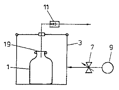
As mentioned, Fig. 1 schematically depicts a closed
container 1 that is to be checked for leaks or to determine
its volume; said container may, for example, be already filled
and be in a testing chamber 3. Chamber 3 can be sealed by
means of, for example, insert cover 5. Via a controlled
valve 7, the test volume, here the volume differential between
chamber 3 and container l, is pressurized by means of a
suction or pressure source 9 in such a way that a pressure
gradient is created across the walls of container 1. In this
embodiment, source 9 empties into chamber 3.

CA 02122250 2003-09-08
6
At or in chamber 3 is another relative-pressure sensor
11, which converts the input-side pressure value into an
electrical output signal. Via a storage control circuit, as
indicated in the schematic by S, electrical output signal el
from sensor 11 is stored in a storage unit 13 in response to
a control signal s that is emitted by a time control unit
(not shown). Output signal elofrom storage unit 13 is fed to
a comparator unit 15 as a pressure reference value. Output
signal el of sensor 11 is present directly at said comparator
unit's second input. After reference value elo is stored,
the plot of the pressure in chamber 3 is monitored at
compa~ator unit 15.
Let us now first consider leakage testing. If container
1 is sealed and storage has been done in storage unit 13,
then sensor output signal el will remain at stored value e1o
once all differential-induced shape changes in container 1
have subsided. On the output side of comparator 15, a
comparison result that at least approximately equals zero
indicates that container 1 is sealed.
If leaks are present in container 1, after reference
value elo is stored as mentioned signal value el will vary
depending on the direction of the pressure gradient across
the container wall; the higher the rate of variation, the
larger the leak. On the output side of comparator 15 there
will be an output signal. The value of this output signal is
a function of the change in pressure in chamber 3 from the
reference pressure associated with the stored pressure
reference value elo.
Comparing the output signal of comparator unit 15 with
predetermined nominal values (not shown) provides an
indication, on the one hand, as to whether a leak is present
as well as, on the other, as to how large said leak is.
Depending on the containers to be tested, minor leaks may be
tolerated.

CA 02122250 2005-12-21
7
If the leak in container 1 is large, then absolutely no
pressure differential will develop across the walls of
container 1: the pressures between the interior of the
container and its environment will quickly equalize via the
leak. Then, however, on the output side of comparator 15 a
null signal will appear, i.e., just as in the case of a sealed
container, and lead to testing errors.
Therefore, as indicated by the dotted lines; preferably
after value elo is stored in storage unit 13, this stored value
is compared to a reference value ref at another comparator
unit 17. The output signal of other comparator unit 17
indicates whether a large leak is present or not. Either when
a predetermined amount of pressure medium is allowed to enter
chamber 3 or when a predetermined amount of gas is removed
from said chamber, in the case of a large leak the pressure
value indicated by reference value ref will not be reached;
this will cause the test result at container 1 to be indicated
by the output signal of other comparator 17.
To test volume, a predetermined amount of pressure medium
is fed to chamber 3 or a predetermined amount of gas is
removed therefrom. As indicated by dotted lines at refs,
storage unit 13 is used here as a reference-value storage unit
in which reference values corresponding to the nominal volumes
of containers that are to be tested are prestored. By
comparing above-mentioned volume reference values refs and the
pressure value that actually arises corresponding to el in the
volume differential in chamber 3 that is dependent on the
interior volume of container 1, i.e., from the output signal
of comparator unit 15, a determination is made as to whether
container 1 has nominal volume or not, or how large the
nominal/actual volume differential is.

CA 02122250 2005-12-21
8
In the case of the embodiment shown in Fig. 2, where the
references used in Fig. 1 are used for the same parts, only
source 9 empties into chamber 3. Via a sealed closure 19,
the input of sensor 11 is connected to the interior of
container 1 that is fitted with an opening. The electronic
analyzer, which is placed behind sensor 11, is depicted just
as in Fig. 1.
As in Fig. 2, Fig. 3 shows another variant in which,
compared to Fig. 2, the arrangements of source 9 and sensor
11 are switched.
In the case of the arrangement shown in Fig. 4, on the
one hand source 9 empties into the interior of a container 1
via sealing connection 19 [and on the other] the input of
sensor 11 is connected to the interior of container 1. The
electronic analyzer shown in Fig. 1, to which sensor 11 is
connected, is provided here as well. The embodiment shown in
Fig. 1 or Fig. 4 is preferably used.
Fig. 5 shows, in the form of a block diagram, a
preferred embodiment of analysis unit I that is partially
outlined with dotted lines in Fig. 1. In the preferred
embodiment, the output signal of sensor 11 is fed to a
converter stage 21, which on the input side comprises an
analog/digital converter 21a, which is immediately followed
by an digital/analog converter 21b. Like the output signal
of sensor 11, the output of digital/analog converter 21b is
fed to a differential amplifier unit 23 that is

CA 02122250 2003-09-08
9
of a known design. The output of differential amplifier unit
23, corresponding to comparator unit 15 of Fig. 1, is
connected to another amplifier stage 25, whose output is
overlaid 28 on the input signal to amplifier 25 via a storage
element 27.
Converter unit 21 and storage unit 27 are controlled via
a timing signal generator 29. This arrangement works as
follows
To store value elo as shown in Fig. 1, from timing
signal generator 29 at measurement point tl in Fig. 6 after
the pressure reaches risingly a predetermined test value 1
and rereaches the predetermined test value diminishingly as
shown in Fig. 6, a conversion cycle at converter unit 21 is
enabled, at which point signal value eloappears at the input
of differential amplifier unit 23. At essentially the same
time, timing signal generator 29 preferably actuates storage
unit 27, causing the output signal value of amplifier 25 to
be fed back as a null-value-balance signal to the amplifier
input. If when value elo was stored the output signal of
amplifier 25 was not equal to zero, then this signal value is
used as a null compensation signal via storage unit 27. By
nulling the signal from amplifier stage 25 at time tl in
Fig. 6, the output signal from amplifier stage 25 from time
tl over the measuring time interval from tl to t2 will be a
function of the change in pressure in chamber 3 from the
reference pressure associated with the stored value e1o at
time ti. Thus, the arrangement permits the direct
measurement of the change in pressure in the chamber during
the measuring time interval tl-tZ using pressure sensor 11,
without the need for use of a reference pressure chamber or a
differential pressure sensor as in the prior art.
As indicated in reference to Fig. 1, the detection of
major leaks can be done in different ways by, e.g., feeding
the output signal value of converter unit 21 to another

CA 02122250 2003-09-08
9a
comparator (not shown), where said output signal value is
compared to reference signal value ref as indicated in Fig. 1
or, as indicated by dotted lines at S1, by switching the
differential amplifier output, which is otherwise connected
to sensor 11, to a reference potential, such as to ground,
immediately before or after, and preferably after,
storage unit 27 is set, and then on the output side of
amplifier unit 25 directly testing the value of e1o to

CA 02122250 2005-12-21
1~
determine whether said value has reached the reference value
as per ref of Fig. 1 or not.
Unlike what is indicated in the case of the preferred
embodiments mentioned above, it is readily possible to omit
the second converter stage, namely digital/analog
converter 21b, and instead, as indicated at 22b by dotted
lines, to provide an analog/digital converter and then
subsequently to process both signals, i.e., elo and el,
digitally.
To check volume, either volume reference values are pre-
entered at converter unit 21, provided, as indicated by
dotted lines at refs, or another digital storage unit is
connected to digital/analog converter 21b directly in order
to convert input digital volume reference values into the
corresponding analog signals and thus to use the arrangement
shown to perform volume measurement as well.
The unit that is shown is exceptionally well suited for
in-line testing of containers such as in a carrousel conveyor
for, e.g., bottles, plastic bottles, etc.
In principle, it is also possible, after a predetermined
test pressure is reached, to compare the electrical output
signal of the sensor to this value or to several pre-entered
values; this can be done on, e.g., a computer, where the
sensor output is read in. The differential with respect to
the set test pressure, i.e., the pressure drop, is determined
by computer (compared to a boundary value entered into the
computer or to a value that is determined from a reference
leak) .

Dessin représentatif
Une figure unique qui représente un dessin illustrant l'invention.
États administratifs

2024-08-01 : Dans le cadre de la transition vers les Brevets de nouvelle génération (BNG), la base de données sur les brevets canadiens (BDBC) contient désormais un Historique d'événement plus détaillé, qui reproduit le Journal des événements de notre nouvelle solution interne.

Veuillez noter que les événements débutant par « Inactive : » se réfèrent à des événements qui ne sont plus utilisés dans notre nouvelle solution interne.

Pour une meilleure compréhension de l'état de la demande ou brevet qui figure sur cette page, la rubrique Mise en garde , et les descriptions de Brevet , Historique d'événement , Taxes périodiques et Historique des paiements devraient être consultées.

Historique d'événement

Description Date
Le délai pour l'annulation est expiré 2011-08-29
Lettre envoyée 2010-08-27
Lettre envoyée 2008-10-24
Inactive : Lettre officielle 2008-08-15
Inactive : Lettre officielle 2007-01-18
Inactive : Paiement correctif - art.78.6 Loi 2007-01-10
Accordé par délivrance 2006-04-11
Inactive : Page couverture publiée 2006-04-10
Lettre envoyée 2006-02-02
Exigences de modification après acceptation - jugée conforme 2006-02-02
Inactive : Taxe finale reçue 2006-01-20
Préoctroi 2006-01-20
Modification après acceptation reçue 2005-12-21
Un avis d'acceptation est envoyé 2005-07-21
Lettre envoyée 2005-07-21
Inactive : Approuvée aux fins d'acceptation (AFA) 2005-05-13
Modification reçue - modification volontaire 2004-11-04
Inactive : Dem. de l'examinateur par.30(2) Règles 2004-05-05
Modification reçue - modification volontaire 2004-04-02
Inactive : Dem. de l'examinateur par.30(2) Règles 2003-10-08
Modification reçue - modification volontaire 2003-09-08
Inactive : Dem. de l'examinateur par.30(2) Règles 2003-03-07
Inactive : Grandeur de l'entité changée 2002-07-30
Inactive : Renseign. sur l'état - Complets dès date d'ent. journ. 1999-05-21
Lettre envoyée 1999-05-21
Inactive : Dem. traitée sur TS dès date d'ent. journal 1999-05-21
Toutes les exigences pour l'examen - jugée conforme 1999-04-29
Exigences pour une requête d'examen - jugée conforme 1999-04-29
Demande publiée (accessible au public) 1994-03-17

Historique d'abandonnement

Il n'y a pas d'historique d'abandonnement

Taxes périodiques

Le dernier paiement a été reçu le 2005-07-14

Avis : Si le paiement en totalité n'a pas été reçu au plus tard à la date indiquée, une taxe supplémentaire peut être imposée, soit une des taxes suivantes :

  • taxe de rétablissement ;
  • taxe pour paiement en souffrance ; ou
  • taxe additionnelle pour le renversement d'une péremption réputée.

Les taxes sur les brevets sont ajustées au 1er janvier de chaque année. Les montants ci-dessus sont les montants actuels s'ils sont reçus au plus tard le 31 décembre de l'année en cours.
Veuillez vous référer à la page web des taxes sur les brevets de l'OPIC pour voir tous les montants actuels des taxes.

Historique des taxes

Type de taxes Anniversaire Échéance Date payée
TM (demande, 5e anniv.) - petite 05 1997-08-27 1997-07-09
TM (demande, 6e anniv.) - petite 06 1998-08-27 1998-06-04
Requête d'examen - petite 1999-04-29
TM (demande, 7e anniv.) - petite 07 1999-08-27 1999-07-27
TM (demande, 8e anniv.) - petite 08 2000-08-28 2000-07-06
TM (demande, 9e anniv.) - petite 09 2001-08-27 2001-07-10
TM (demande, 10e anniv.) - générale 10 2002-08-27 2002-07-15
TM (demande, 11e anniv.) - générale 11 2003-08-27 2003-07-22
TM (demande, 12e anniv.) - générale 12 2004-08-27 2004-07-22
TM (demande, 13e anniv.) - générale 13 2005-08-29 2005-07-14
Taxe finale - générale 2006-01-20
TM (brevet, 14e anniv.) - générale 2006-08-28 2006-07-12
2007-01-10
TM (brevet, 15e anniv.) - générale 2007-08-27 2007-07-23
TM (brevet, 16e anniv.) - générale 2008-08-27 2008-07-10
TM (brevet, 17e anniv.) - générale 2009-08-27 2009-08-05
Titulaires au dossier

Les titulaires actuels et antérieures au dossier sont affichés en ordre alphabétique.

Titulaires actuels au dossier
MARTIN LEHMANN
Titulaires antérieures au dossier
S.O.
Les propriétaires antérieurs qui ne figurent pas dans la liste des « Propriétaires au dossier » apparaîtront dans d'autres documents au dossier.
Documents

Pour visionner les fichiers sélectionnés, entrer le code reCAPTCHA :


Pour visualiser une image, cliquer sur un lien dans la colonne description du document. Pour télécharger l'image (les images), cliquer l'une ou plusieurs cases à cocher dans la première colonne et ensuite cliquer sur le bouton "Télécharger sélection en format PDF (archive Zip)" ou le bouton "Télécharger sélection (en un fichier PDF fusionné)".

Liste des documents de brevet publiés et non publiés sur la BDBC .

Si vous avez des difficultés à accéder au contenu, veuillez communiquer avec le Centre de services à la clientèle au 1-866-997-1936, ou envoyer un courriel au Centre de service à la clientèle de l'OPIC.


Description du
Document 
Date
(aaaa-mm-jj) 
Nombre de pages   Taille de l'image (Ko) 
Dessin représentatif 1999-05-12 1 6
Description 2003-09-07 13 488
Revendications 2003-09-07 7 296
Revendications 1995-11-15 4 228
Description 1995-11-15 10 687
Revendications 2004-04-01 7 294
Revendications 2004-11-03 8 315
Dessin représentatif 2005-05-16 1 4
Abrégé 1995-11-15 1 19
Dessins 1995-11-15 3 40
Abrégé 2005-12-20 1 20
Description 2005-12-20 13 511
Rappel - requête d'examen 1999-04-27 1 117
Accusé de réception de la requête d'examen 1999-05-20 1 179
Avis du commissaire - Demande jugée acceptable 2005-07-20 1 160
Avis concernant la taxe de maintien 2010-10-11 1 170
PCT 1994-04-25 9 272
Correspondance 2006-01-19 1 35
Correspondance 2007-01-17 1 12
Correspondance 2008-08-14 1 14
Correspondance 2008-10-23 1 12
Correspondance 2008-10-08 2 47
Taxes 2008-07-13 2 57
Taxes 1996-06-23 1 52
Taxes 1995-05-29 1 49
Taxes 1994-07-12 1 58