Note : Les descriptions sont présentées dans la langue officielle dans laquelle elles ont été soumises.
1115-24
SENSOR FOR DETECTING METAL OBJECTS
IN PINBALL MACHINES.
Technical Field
This invention relates to a sensor for detecting the
i position of a metal object and in particular to a sensor
appropriate for detecting the position of a metal object in a
` space sandwiched between parallel planes, for example.
s~
Technical Background
Devices requiring a sensor for detecting the position of
'i a metal object include metal detectors, game machines, etc.
For example, with some game machines, a player moves a metal
object, such as a metal ball, in a specific space set within
the game machine and may or may not win the play depending on
the destination of the metal ball. Pinball machines are
typical of such game machines; with a pinball machine, a player
~- plays a game by dropping a pinball ~a metal ball) in a space
~- sandwiched between parallel planes in which a large number of
obstacles are located.
l ~ The pinball machine has a board face for providing a space
i ~ required to move pinballs, a glass plate spaced from the board
1~ face at a given interval to cover theboard face, and a
propelling mechanism for propelling pinballs to the top of the
board face. The pinball machine is set up so that the board
ace becomes substantially parallel to the vertical direction.
The~bioard face is formed with a plurality of safe holes, into
whlch the player attempts to cause a pinball to enter for a
winning play ~hit), in response to which the pinball is
; dlscharged from the board face, and an out hole into which
pinballs not entered in the safe holes are finally collected
for discharging the pinballs from the board face.
A large number of pins ~nails) are set up substantially
vertical to the board face in a state in which they project
from the board face as far as the diameter of a pinball as
obstac1es with which pinballs dropping along the board face
~ ';''''`".'''''''-'
frequently collide for causing the motion direction thereof to
fluctuate. The pins are located on the board face with a
distribution determined so as to guide pinballs colliding with
the pins toward or away from the safe holes while causing the
motion directions of the pinballs to fluctuate.
Since the pinball machines have such a structure, some
pinball machines may easily register hits and some may be
caused to hit only with difficulty, depending on a slight
difference in pin layout or inclination. Also, at a single
machine, somesafe holes may be high in hit average and some may
be low; the hit average difference among the safe holes varies
from one machine to another.
At game houses, etc., having a large number of such game
machines, it is important on management such as profit
management and customer management for personnel of the game
house to know the characters of the respective game machines.
For example, if many machines are easy to hit, the game house
suffers a loss; lf most machines are hard to hit, the customers
lose interest in play and the game house will lose business.
~ Therefore, personnel need to know the characters of the
j"7~ respective game machines installed in the house and take action
accordingly.
i~ To this end, a passage of a pinba-ll is detected in pinball
machines. As a sensor used for this purpose, a sensor provided
with an upper sheet and a lower sheet forming contact pairs is
disclosed in Japanese Patent Publication No.Sho 64-3560, for
example. In the art described here, a pinball is placed on the
upper sheet and presses it, whereby contact pairs contact in
sequence as the pinball passes for detecting the passage of the
pinball.
However, since the conventional sensor h~s the contlact
pairs, a layout of the sheets is limited; thesheets can be laid
out only along passages of pinballs. Thus, the sensor cannot
detect pinball motion from the viewpoint of seeing the entire
board face. Thus, it is difficult for the sensor to determine
how pinballs enter the save holes and the out hole.
: A ~ `
Since a pinball is detected by physical contact of the
contact pairs, pressure against the sheet may become weak
depending on the pinball motion state, in which case some
contact pairs cannot contact and the pinball may be unable to
be detected. Also, a contact failure may occur due to
abrasion, corrosion, or the like of the contact pairs.
Further, the contact pairs may erroneously contact due to
vibration, chattering, or the like. Thus, the sensor has a
problem of lacking reliability.
Further, the sensor, which uses pressure of pinballs, also
introduces a problem of delicately affecting pinball motion.
Such problems may occur on other devices as well as the
pinball machines. Therefore, it is desired to work out some
countermeasure.
.. ~ .
. ~: "
Di~closure of Invention
It is therefore an object of the invention to provide a
sensor for detecting the position of a metal object which can
detect any desired position of a metal object in a specific
space without contact with the metal object and without using
contacts involving physical contact, and to produce the
detection result providing high reliability.
To this end, according to the invention, there is provided
a sensor for detecting a position of a metal object comprising
a plurality of transmitting lines being energized for
generatlng a magnetic field, a board for supporting the
transmitting lines, a plurality of reception lines being
electro-magnetically coupled with the transmitting lines for
detecting a magnetic flux change made by approach of the metal
ob~ect, and a board for supporting the reception lines, wherein
the transmitting lin'esland the reception lines are madel of
conductive thin films formed on their respective boards having
turn forms having sending and returning paths, and are laid out
in a direction to cross each other with the boards between.
The transmitting lines and the reception lines can cross
each other so that their cross portions are laid out like a
matrix.
The areas surrounded by the sending and returning paths of
the transmitting lines and the reception lines in the cross
portions can be made substantially quad~ilaterals, for example.
Each of the transmitting lines and the reception lines can
comprise two layers of a metal pattern formed on their
respective boards and a metal film formed on the metal pattern
as the conductive thin film. The transmitting and reception
lines can each comprise a transparent conductive film formed
like the board and a metal film formed on the transparent
conductive film as the conductive thin film. In these cases,
glass boards may be used as the boards.
The direct current resistance value of each of the
transmitting lines and the reception lines can be set in the
' range of 20 to 200Q, for example.
J When an electric current flows into a tuned transmitting
j line for generating a magnetic field, an induced current is
induced on the reception line near the transmitting line by
electro-magnetic induction. At this time, if a metal object
approaches the transmitting line and the reception line, an
eddy current is generated on the surface of the metal object
in a direction to negate a magnetic flux by the transmitting
line. Thus, the scale of the induced current induced on the
reception line is changed by the effect of the eddy current.
~-~The approach of the metal object can be detected by detecting
the change.
Brlef Description of the Drawings
Figure l is a schematic front view showing the form of a
detection matrix used in a first embodiment of the invention;
Figure 2 is perspective views of a game machine and the
detection matrix as a conceptual exploded view;
Figure 5 is an enlarged sectional view of one example of
a transmitting or reception line used in the invention;
Figure 6 is a block diagram showing the portion on the game
machine side in one example of a signal processing system used
in the invention;
Figure 7 is a block diagram showing the main controller
side in the example signal processing system used in the
invention;
Figure 8 is a schematic waveform chart showing a voltage
waveform fed to transmitting lines;
Figure 9 is a schematic front view showing the form of
transmitting or reception lines according to a second :~:
embodiment of the invention;
Figure 10 is a schematic front view showing the form of :~
transmitting or reception lines according to athird embodiment ;
of the invention;
Figure 11 is a schematic front view showing the form of
transmitting or reception lines according to a fourth ~ -. ,
embodiment of the invention; ;~ -
Figure 12 is a schematic front view showing the form of a
detection matrix according to a fifth embodiment of the ;.. : .;
invention;
~;Figure 13 is a schematic front view showing the form of a
detection matrix according to a sixth embodiment of the
. ~invention; ;;~. 1~"
Figure 14 is a schematic front view showing the form of a .'~
detection matrix according to a seventh embodiment of the
invention;
~;Figure 15 is an enlarged sectional view of an inner glass
"'~unit having a detection matrix according to an eighth . ;i~
embodiment of the invention; ~;. .;;~.~
~Figure 16 is an enlarged sectional view of a transmitting .~ .
i.~ or reception line according to a ninth embodiment of the ~ `'
;~lnvention; and
Figure 17 is a pérspective view of a slot machine according . ;~
to a tenth embodiment of the invention. `:.
.."'" ~''
Best Mode for Carrying out the Invention
,-.Re~erring now to the accompanying drawings, there are shown .
preferred embodiments of the invention.
. ::
~A
Figures 1 to 8 shows a first embodiment of theinvention.
In the first embodiment, a metal sensor is used as a metal
detector for application to a game machine 10.
The game machine 10 has a board face 11 for providing a
space required to move metal objects B, a glass cover 10a
spaced from the board face at a given interval to cover the
board, and a propelling mechanism for propelling metal objects
to the top of the board face 11, as shown in Figures 2 and 3.
The game machine 10 is set up so that the board face 11 becomes
substantially parallel to the vertical direction. The board
face 11 of the game machine 10 is formed with a guide rail 12
for defining a game area. This means that the game area is
provided inside the guide rail 12. A large number of pins
(nails) 13, for bouncing metal objects B are hammered into the
board face 11 in the game area. A plurality of safe holes 14a,
are made at various points and one out hole 15 is made at the
bottom of the game area.
The pins 13 are set up substantially vertical to the board
^~face 11 so that they project from the board face 11 as far as
the diameter of the metal object B, as shown in Figure 3.
The pins 13 are laid out as obstacles along the course with ,~
which a metal object dropping between the pins 13, 13 along the
board face 11 frequently collides for causlng the motion ,'".~., i,".~J'',~
direction of the metal object to fluctuate. More specifically,
the pins 13 are grouped into pin strings or pin groups 13a, as ~ .`
shown in Figure 2. The pin strings or pin groups 13a are
located as a distribution determined so as to guide the metal
objects colliding with the pins 13 toward or away from the safe ~`
hole~ 14a while causing the motion directions of the metal
objects to fluctuate in response to the metal object propelling ii ~;
position orl drop start position and the motion direction,
j speed, etc., of the metal object at the time. ;~
r~ ~ The safe hole 14a is a hole into which a player trys to
cause a métal object to enter for a winning play (hit) through
which the metal object is discharged from the board face 11.
'~On the other hand, the out hole 15 is a hole into which metal
;~ 6
~A -~
objects not entering into the safe holes 14a are finally
collected for discharging the~pinballs from the board face 11.
The front glass cover lOa for covering the board face 11
consists of a surface glass unit 16 and an inner glass unit 17.
The propelling mechanism has a propelling handle 18 and a
drive mechanism (not shown). The handle 18 islocated on the
front face of the game machine 10 for a player to propel metal
objects by turning the handle 18 at any desired angle.
A ball saucer 19 for receiving metal objects paid out from
the game machine 10 is also located on the front face of the
game machine 10. When a metal object projected to the top of
the board face 11 falls into any safe hole 14a, a predetermined
number of metal objects are paid out for a winning play.
A dete^tion matrix 20 forming a metal sensor is disposed
along the board face 11 of the game machine 10, as shown in
Figures 2 and 3. The detection matrix 20 is built on the
inside when viewed from the game machine 10, namely, into the
inner glass unit 17, which is the side nearest the ball face
11, of the surface glass unit 16 and the inner glass unit 17
making up the front glass cover lOa covering the board face 11.
The inner glass unit 17 comprises three laminated layers
of an internal protection glass plate 17a which is a protection
sheet for reception lines 26, a glass base board 17b, and an
outer glass plate 17c which is a protection sheet for
transmitting lines 22. The reception lines 26 (described
below) are sandwiched between the internal protection glass
plate 17a and theglass base board 17b. The transmitting lines
22 ~described below) are sandwiched between the glass base
board 17b and the outer glass plate 17c.
A transparent conductive film 28 for shielding is provided
on the full surface of the outer glass plate 17c'on the surface
of the transmitting lines 22. The transparent conductive film
28 is made of an indium tin oxide (I.T.O.) film, tin oxide
film, etc.
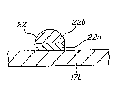
As shown in Figure 1, each transmitting line 22 has a
parallel section 22P comprising a sending path and a returning
' . :;', .
.~; '': ' '
path in parallel and a turn section 22T at which the sending
path turns to the returning path for making a turn part ~or a
loop).
Each reception line 26 has a parallel section 26P
comprising a sending path and a returning path in parallel and
a turn section 26T at which the sending path turns to the
returning path for making a turn part (or a loop). A plurality
of the transmitting lines 22 are laid out on the glass base
board 17b so that their parallel sections 22P are arranged
within the same plane and become parallel to each other.
Likewise, a plurality of the reception lines 26 are laid out
on the glass base board 17b so that their parallel sections 26P
are arranged within the same plane and become parallel to each
other. Thetransmitting lines 22 are arranged in a row
direction and the reception lines 26 are arranged in a column
direction, for example, so that they cross each other to make
up the detection matrix.
To form the transmitting line 22, as shown in Figure 5,
first a film of metal such as aluminum is formed on the surface
of one side of the glass base board 17b by means of deposition
or the like for forming a transmitting line pattern 22a like
a turn. Next, on the deposition part, a film of metal such as
copper is formed along the pattern by means of plating,
deposition, or the like for forming a metal pattern 22b.
~ikewise, to form the reception line 26, aluminum is deposited
on the surface of the other side of the glass base board 17b
for forming a reception line pattern like a turn on which a
~ilm of copper is formed for forming a metal pattern.
Reactivity of the transmitting line 22 and/or the reception
line 26 can be controlled by changing the film thickness of the
copper film.~ " ~
For example, if the copper film is thickened, direct
current resistance of the transmitting line 22 and/or reception
line 26 is lowered, increasing the reactivity to metal objects.
The inner glass unit 17 comprises the internal protection
glass plate 17a bonded to the reception lines 26 of the glass
'
,~ j, .
base board 17b and the outer glass plate 17c bonded to the
transmitting lines 22 by a transparent adhesive.
As shown in Figure 1, a plurality of the transmitting lines
22, each of which makes a U turn for parallel sending and
returning paths, are disposed on the same plane in parallel in
one direction. Likewise, a plurality of the reception lines
26, each of which makes a U turn for parallel sending and
returning paths, are disposed on the same plane in parallel in
one direction.
The respective reception lines 26 are located near the
respective transmitting lines 22 so that they can be electro~
magnetically coupled. That is, the reception lines 26 are
disposed in a direction to cross at right angles to the plane
parallel to each transmitting line 22 (that is, with the plane
containing the transmitting line 22 like a turn and the plane
containing the reception line 26 like a turn parallel to each
other) so that the electro-magnet characteristic changes as
metal such as a metal object B approaches.
In the front view of the detection matrix in Figure 1,
quadrilateral portions surrounded by the sending and returning
paths of the transmitting lines 22 and the reception lines 26
crossing each other provide detection units for sensing a metal
object, 20a. The detection unit 20a is formed substantially
like a square in the embodiment, but is not limited to the
quadrilateral or square as shown in embodiments described
below.
~ xternal connection terminals 23 and 27 are provided at the
ends of the transmitting lines 22 and the reception lines 26.
AQ shown in Figure 4, some of the detection units 20a
correspond to the positions of the safe holes 14a~
~ he pattern form!s of the transmitting lines 22 and !the
reception lines 26 are very fine in relation with the size of
a metal ob~ect B; if the detection units 20a are too large,
resolution worsens and if they are too small, a plurality of
detection units respond to one metal object, thus their
poslt1onal relationship becomes hard to grasp.
"~'~ ,",, .........' :,'
. "~
~,' ~ ,' '' .,'..'' ,',` .''
i~
~ ~-
Then, the DC resistance values of the transmitting lines
22 and the reception lines 26 are set to preferably 10 to 200n
or about 25Q as the optimum value as the value at which
reactivity to metal objects B is the best.
As shown in Figure 1, the turn width (spacing between the
sending and returning paths) of each transmitting line 22,
reception line 26, a, is set to preferably 4 to 16 mm or 8 mm
as the optimum value as the width at which reactivity for
detecting metal objects B is good. The width between the
transmitting lines 22 and between the reception lines 26, b,
is 0.5 to 2 mm or so, indicating a good result.
A pattern of the detection matrix 20 appropriate for the
game machine 10 consists of, for example, 32 ~ows of the
transmitting lines 22 and 32 columns of the reception lines 26
forming 1024 detection uni~s 20a in total.
The thickness of a conductor forming each of the
transmitting lines 22 and the reception lines 26 also has a
large effect on the sensitivity. That is, if the conductor is
thin, impedance is too high; if it is thick, the inner diameter
of the pattern becomes small, worsening the sensitivity.
Further, the detection matrix 20, which is contained in the
inner glass unit 17 covering the board face 11, needs to be
made as thin as possible so as not to spoil the view when
playing. Then, the thickness of each of the conductors forming
the transmitting lines 22and the reception lines 26 is
preferably set to 20 to 50 mm.
A slgnal processing system providing the metal detector for
detecting metal objects is as shown in Figures 6 and 7.
The signal processing system, which is under the control
of a main controller 30, comprises the main controller 30, a
logic controller 31 for repeating control signals, etc. from
the main controller 30, an impedance matching driver 32, a DC
offset converter 33, a hold section 34, and an A/D converter
35 making up a circuit system for inputting data from the
detection matrix 20 to the main controller 30, a timing
generator 36, a power supply unit 37, and an external
; ~,~
~'.,, 10 ,'
. .
l'"~
.
connection connector 38. The logic controller 31 and the
circuit system are connected to the external connection
connector 38. The main controller consists of a computer
containing a central processing unit and a main memory (not
shown).
Installed on the side of the game machine 10 in the signal
processing system are an output system 40 for feeding power
into a plurality of the transmitting lines 22 of the detection
matrix 20 and an input system 50 from a plurality of the
reception lines 26. The outputsystem 40, which is installed
on the side of the transmitting lines 22, is provided with a
transmitting driver 41 for inputting signals to the
transmitting lines 22 in sequence at a predetermined period and
a decoder 42 connected to the transmitting driver 41 for
controlling the transmitting driver 41 so that it operates in
sequence in response to control signals from the main
controller 30, as shown in Figure 6. A continuous sine wave
with 0 V as the center having frequency 1 MHz is preferred, for
example, as shown in Figure 8, as a voltage waveform 81 fed to
the transmitting line 22.
Further, the output system 40 comprises a logic sequencer
43, a timing generator 44, and a transmitting line row counter
45.
The logic sequencer 43 operates in response to control
8ignal~ from the main controller 30; it synchronizes the
decoder 42 in the transmitting system with a multiplexer 52
~described below) in the receiving system and also controls the
beginning and end timings of a scanning period of signals
output in sequence by the decoder 42.
The timing generator 44 determines the scanning period,
which requires a minimum of 10 KHz to cover a movement of a
metal object on the board face 11 of the game machine 10, and
i9 set to 100 KHz in the embodiment. The transmitting line row
counter 45 counts the scanning period for determining the
transmitting llne 22 to be scanned.
The input system 50, which is installed on the side of the
~ ~ 11 , ',' :''
~ ~A ,.; :,;
:
:~
~l~
`
reception lines 26, ls provided with a converter 51 connected
to the reception lines 26 for converting a current representing
; an electro-magnetic characteristic value of each of the
reception lines 26 into a voltage signal that can be handled
by digital devices at the following stages and a multiplexer
52 connected to the converter 51 for receiving signals in
sequence from the reception lines 26 and outputting them.
A reception line column counter 53 located following the
logic sequencer 43 of the output system 40 is connected to the
multiplexer 52. The output system 40 and the input system 50
are synchronized with each other by the transmitting line row
counter 45 and the reception line column counter 53 connected
to the logic sequencer 43. In one synchronization mode, for
example, one of the reception lines 26 is detected per scan of
the transmitting lines 22.
In contrast to the synchronization mode, for example, the
reception lines 26 scan once per transmitting of one of the
transmission lines 22 for detection.
An output of the multiplexer 52 of the input system S0 is
connected via an impedance converter 54 to the external
~i ~ connection connector 38 to the main controller 30.
~fY ~ Next, the operation of the embodiment is described.
In Figure 7, when an address signal and a control signal
are output from the main controller 30 via an address bus and
0ntrol bus to the logic controller 31, the logic controller
;)i~ 31 transfers the signals to the game machine lO through the
; external connection connector 38.
In Figure 6, in the game machine 10, the logic sequencer
43 of the output system 40 issues a sequence signal based on
the input signals to the decoder 42, the timing generator 44,
~. .
~; ~ ~ the transmitting line row counter 45, and the reception line
column counter 53.
; The timing generator 44 determines a scanning period of
each transmitting line 22 of the detection matrix 20. The
transmitting line row counter 45 counts scanning period signals
~or determinlng the transm1tt~ng l1ne 22 to ~e driven. The
! '' '~: , ' ',
counter 45 operates in synchronization with the sequence signal
from the logicsequencer 43.
The decoder 42 controls the transmitting driver 41 so that
the transmitting driver 41 outputs a signal in sequence to the
transmitting lines 22 at a predetermined period.
When receiving current signals representing
electro-magnetic characteristic values appearing on the
reception lines 26, the converter 51 converts the current
signals into voltage signals that can be handled by digital
circuitry at the following stages.
When receiving the signals into which the signals from the
reception lines 26 are converted, the multiplexer 52 outputs
the signals in sequence on a predetermined period. The decoder
42 in the transmitting system and the multiplexer 52 in the
receiving system operate in synchronization with each other in
response to the count of the transmitting line row counter 45
and the count of the reception line column counter 53 operating
according to control signals of the logic sequencer 43
operating according to control signals.
The logic sequencer 43 causes the converter 51 and the
multiplexer 52 in the receiving system to detect information
on one of the reception lines 26 per scan of the transmitting
line~ 22 or in contrast causes the reception lines 26 to scan
once per transmitting of one of the transmitting lines 22 for
detection.
a voltage signal having a waveform as shown in Figure
i8 applied to one transmitting line 22, an alternating field
occurs ln the parallel section 22P of the transmitting line 22,
whereby an alternating voltage is induced in each reception
l~ne 26 crossing the transmitting line 22 by electro-magnetic
induction
At this time, if a metal object enters a space assumed by
any detection unit 20a belonging to the transmitting line 22,
an eddy current is induced in the metal object. The eddy
current generates a magnetic field in a direction to negate a
magnetic flux occurring from the parallel section 22P. Thus,
. " ~
'- 13
E~
the scale of electro-magnetic induction with respect to the
reception line 26 crossing the transmitting line 22 at the
detection unit 20a changes and induced current on the reception
line 26 becomes small. On the other hand, such a change does
not occur on other reception lines 26 crossing the same
transmitting line 22 and the scale of induced current does not
change. The reception line 26 having its parallel section 26P
at the position of themetal object is scanned by the analog
multiplexer 52 and the signal is finally sent to the main
controller 30 for comparison. As described below, the main
controller 30 can check the reception line columns for
detecting a specific reception line 26 different from others
in output. It can also check the transmitting line rows, for
example, for detecting the current transmitting line 22 being
driven. Therefore, the detection unit 20a in which the metal
object exists can be known from information on both the
reception and transmitting lines.
The transmitting line 22 being driven can be known, for
example, by obtaining the count of the transmitting line row
counter 45; the reception line 26 selected by the analog
multiplexer 52 can be known, for example, by obtaining the
count of the reception line column counter 53. Track of the
position of the metal object can be kept as coordinates of the
position at which the transmitting line rows and the reception
line columns cross each other.
Since the number of the detection units 20a is 1024 in
total, from 32 rows of the transmitting lines 22 and 32 columns
; of the reception lines 26, the metal object can be detected
-~ even if it passes through anyof the safe holes 14 and the out
hole 15.
~ Since the voltage wlaveform 81 to the trans~itting line 22
~ is a continuous sine wave with 0 V as the center, noise as with
'r a square wave does not occur and the effect on other devices
, such as the main controller 30 can be prevented.
A sensor signal output from the multiplexer 52 is
impedance-converted by the impedance converter 54. The
14
''"' ~'''``",'`'.
~ ~'
resultant sensor signal output from the impedance converter 54
is input through the external connection connector 38 to the
impedance matching driver 32 on the side of the main controller
30 for impedance matching. The DC offset converter 33 following
the impedance matching driver 32 receives only a reaction wave
of output from the detection matrix 20 and outputs it to the
hold section 34.
The hold section 34 temporarily stores data transferred at
high speed until the A/D converter 35 at the following stage
completes A/D conversion. The A/D converter 35 converts analog
signals from the detection matrix 20 into digital signals in
predetermined bit units, such as 12 bits, and sends the
resultant digital data via a data bus to the main controller
30. The operation of the hold section 34 is synchronized with
that of the A/D converter 35 in response to a signal ofthe
logic controller 31 or the timing generator 36.
The A/D converter 35 may be provided with another output
terminal connected to the memory (not shown) for storing motion
of all metal objects on the detection matrix 20 for a long
time.
Since the detection matrix 20 consists of the transmitting
lines 22 and the reception lines 26 which make U turns in
parallel and are at right angles to each other, its pattern is
simple and unobtrusive and can be easily manufactured with wire
such as copper wire. If the line diameter of each of the
transmltting lines 22 and the reception lines 26 of the
detection matrix 20 is made 20 mm or more, DC resistance lowers
for providing good reactivity.
The transparent conductive film 28 on the surface of the
outer glass unit l~c has functions of shielding electric
effects of metàl and inductors from the outside and of raising
reactivity to metal objects.
The positions of the detection units 20a corresponding to
the safe holes 14a are stored and further the position of the
out hole 15 is also stored (without detecting metal objects at
the out hole lS, the number of metal objects propelled to the
",~ 15 ,,,,,,.;,,",",
A~
: r
board face 11 can be counted as the number of incomingballs) ~ z
for watching how metal objects enter the holes during the ~`-
progress of games. Locking up the game machine on a win is ~-
possible and a check is made for an error caused by illegal
operation according to the situation. Machines where metal ~
objects very easily enter only specific safe holes, machines ~ -
where metal objects hardly enter safe holes, etc., are detected
for use as data to adjust a fluctuation amount imparted to
metal objects by pins, etc. -~
Next, a second embodiment of the invention will be
discussed.
Figure 9 shows the form of transmitting or reception lines
according to the second embodiment of the invention. That is, ~-~
the transmitting lines ~or reception lines) 222 are bent like
a zigzag. The second embodiment is the same as the first
embodiment except for the form of the transmitting or reception
lines. -;
Next, a third embodiment of the invention will be
discussed.
Figure 10 shows the form of transmitting or reception lines
according to the third embodiment of the invention. That is,
the transmitting line (or reception line) 322 has the form
swollen like a circle in the portion of a detection unit 20b.
The third embodimentis also the same as the first embodiment
except for the form of the transmitting or reception lines. ~
Next, a fourth embodiment of the invention will be ~;
discussed.
Figure 11 shows the form of transmitting or reception lines
according to the fourth embodiment of the invention. That is, ;~
the transmitting line (or reception line) 422 is bent like a
zigzag and has the form swollen like a square in the portion
of a detection unit 20c and the zigzag form is engaged with
that of its adjacent transmitting or reception line. The
fourth embodiment is also the same as the first embodiment
except for the form of the transmitting or reception lines.
As shown in the second to fourth embodiments, the ~i~
16
transmitting or reception lines can have various forms
according to applications, purposes, etc. The transmitting and
reception lines may be of different line forms in combination.
:~ Next, a fifth embodiment of the invention will be
''! discussed.
; Figure 12 shows the form of a detection matrix according
to the fifth embodiment of the invention. That is, a plurality
of transmitting lines 522 and aplurality of reception lines 526
are introduced from the same direction ~in the Figure 12, from
bottom to top) and bent and extended at an angle of 45 degrees
in directions to cross each other for forming a layout of a
detection matrix 520. The fifth embodiment is the same as the
first embodiment except for the form of the detection matrix.
Next, the operation will be described.
The fifth embodiment is designed so that an area 526A and
an area 522B become substantially the same in pattern length,
as shown in Figure 12. Thus, the transmitting lines 522 and
the reception lines 526 differ less in total length.
Therefore, as compared with the first embodiment, the
transmitting lines 522 and the reception lines 526 are
substantially the same in DC resistance value and DC resistance
can be easily averaged on the transmitting lines 522 and the
reception lines 526; as a result, reactivity can be averaged.
In the examples given above, the transmitting lines 522 and
the reception lines 526 are substantially the same in DC
resistance value. However, they may differ in DC resistance
value depending on applications, purposes, etc., as is the case
wlth the sixth and seventh embodiments of the invention.
Figure 13 shows the form of a detection matrixaccording to
a sixth embodiment of the invention. The sixth embodiment is
the qame as the first embodiment except for the form of!the
detection matrix.
In the sixth embodiment, an area 122A and an area 126B
differ extremely in pattern length. Further, in the area 126B,
a line portion 126a and a line portion 126b differ in pattern
length. Thus~ the transmitting lines 22 and reception lines
17
., ~
26 have different DC resistance values.
Figure 14 shows the form of a detection matrix according
~ to a seventh embodiment of the invention. The seventh
;~ embodiment is the same as the first embodiment except for the
form of the detection matrix.
In the seventh embodiment, an area 222A, an area 226B,
, and an area 227B also differ in pattern length. In the area
~ 227B, a line portion 227a and a line portion 227b differ in
A, pattern length. Thus, the transmitting lines 22 and reception
lines 26 differ in DC resistance value.
- Thus, the detection matrix can have various forms according
;i to applications, purposes, etc.
Next, an eighth embodiment of the invention will be
discussed.
Figure 15 shows the structure of an inner glassunit having
a detection matrix according to the eighth embodiment. That
is, the inner glass unit 817 comprises four layers of an
internal protection glass plate 817a, a reception glass base
board 817b, a transmitting glass base board 917b, and an outer
~;~ glass plate 817c, which are laminated on each other. A
plurality of reception lines 826 turned in parallel are formed
on one side of the reception glass base board 817b, on which
;~ the internal protection glass plate 817a is put.
A plurality of transmitting lines 822 turned in parallel
are formed on one side of the transmitting glass base board
917b~ on which the outer glass plate 817c is put. Then, the
inner glass unit 817 is manufactured by putting the board face
of the reception glass base board 817b and the board face of
the transmitting glass base board 917b together using a
transparent adhesive. Others are the same as the first
embodiment.~ "
The inner glass unit 817 is thus manufactured by putting
the two glass base boards 817b and 917b together to make it
easy to manufacture the inner glass unit 817.
In the embodiment, two glass base boards 817b and 917b may
be made one glass base board having both sides undergoing
,~
18
pattern treatment for forming the turned transmitting lines 822
and the turned reception lines826.
Pattern treatment may also be applied to the internal
protection glass plate 817a and the outer glass plate 817c.
The glass base boards 817b and 917b may be made of plastic
films as well as glass.
Next, a ninth embodiment of the invention will be
described.
Figure 16 shows a transmitting or reception line according
to the ninth embodiment. That is, to form the transmitting
line 922, a transparent conductive pattern 922a of an I.T.O
film is formed on one surface of a glass base board 117b, on
which a film of a metal pattern 922b is formed by depositing,
plating, or the like of metal such as copper along the
transparent conductive pattern.
The I.T.O. film can be formed by thin film techniques such
as sputtering, for example. Likewise, to form the reception
line, a transparent conductive pattern of an I.T.O film is
formed on the other surf~ce of the glass base board 117b, on
which a film of copper is formed.
According to such a structure, if the copper pattern of the
transmitting line 922 or reception line is broken, the
transparent conductive pattern under thecopper pattern is still
cannected, thereby preventing the transmitting or reception
line pattern from being broken.
Copper foil may be applied by a conductive adhesive rather
than forming a copper film on the I.T.O film.
In the embodiments, the game machine has been discussed,
but use of the detection matrix is not limited to the game
machine. For example, the detection matrix can be used to
détect a distribution,lmovément,~etc., of metal objects. ! To
use the detection matrix for detecting a distribution of metal
objects, for example, if a metal piece of a specific pattern
ls attached to each commodity and the commodities are placed
like the detection matrix, the presence or absence of the
commodities can be detected. Therefore, it can be used for
' 1 9
.A
' inventory management of the commodities. By attaching similar
metal pieces to articles, the detection matrix can also be used
for quantity control. In addition, it can be applied to a
,,3, detector for counting and examining metal objects at prize
; exchange places, etc.
Next, a tenth embodiment of the invention will be
described.
Figure 17 shows a slot machine according to the tenth
embodiment of the invention. That is, at the slotmachine 101,
a plurality of common displays 112 are provided on the outer
peripheral surfaces of six rotators 111. A player starts
playing a game by inserting a medal into a medal slot 121 and
pulling a handle 122 toward them. Then, the rotators 111
rotate at high speed and the player stops the rotators 111 in
sequence by pressing stop buttons 123 corresponding thereto in
sequence.
Any one of the displays on each rotator 111 is positioned
on a display window 113 for each game. When all displays 112
positioned on the display windows 113 provide a predetermined i ;~
win display, such as "7," a predetermined number of medals, for
example, are paid out to the player through a win slot 125 for ;;
the winning play.
Each rotator 111 is made of a belt or sheet of a
; nonconductor such as plastic or rubber and is rotated by two
belt pulleys ~not shown). Each rotator 111 is positioned with ;` `
metal such as iron ~not shown) attached to the position of a ~ i
predetermined win display, such as "7." The display windows `-~
113 are covered with a front glass cover 131 which has a
similar structure to that of the inner glass unit 17 in the
first embodiment ~see Figure 3). The inner glass unit 17 is
formed withla detection matrix 20 providing a metal sensor.
Thedetection matrix 20 serves as a metal detector for detecting
:~ metal as in the first embodiment and will not be discussed
Next, the operation will be described. ~ ;
When the rotators 111 stop, if all of the displays
s ~ 20
, - .
~'~`'
positioned on the display windows 113 provide a predetermined
win display, such as "7," the condition is detected by the
detection matrix 20. An internal CPU, such as the main
controller 30 as shown in Figure 3, is informed of the
positions of metal sensed by the detection matrix 20. When the
CPU acknowledges that the displays provide a predetermined win
display, a predetermined number of medals, for example, are
paid out to the player through the win slot 125 for the winning
play accordingly.
The detection matrix 20 may be installed in the slot
machine 101 as well as formed on the display windows 113 on the
front of the slot machine lOl. To detect the metal positions,
the start positions of the rotators 111 are checked by the
detection matrix 20 and then the metal positions may be
detected by the internal CPU.
As in the first embodiment, the front glass cover 131 in
the tenth embodiment may consist of a surface glass unit 16 and
an inner glass unit 17.
In the embodiments, for example, the detection matrix can
provide a metal form determination device for determining the
metal form like a printed wiring board or an indication
position detection sensor such as a touch sensor. For example,
when the metal wiring portion of a printed wiring board is
placed on the detection matrix, the metal form determination
device can detect the position of metal. When an indication
member having at least a metal object on the tip is used and
the tip is made to approach any position on the detection
matrix, the indication position detection sensor detects the
indication position by the detection matrix.
If the density of the detection matrix is made appropriate,
metal objects can belltraced and games can also be monitored in
detail. The detection matrix may be disposed on the rear of
the board face of the game machine.
The conductors forming the transmitting lines 22 and the
reception lines 26 may be metal such as aluminum or gold as
well as copper or transparent conductive films such as indium
21
"
A~
. ~ ~
s
: S
oxide films or tin oxide films.
In the embodiments described above, each sensor comprises
a detection matrix, which has a plurality of transmitting lines
'~ and reception lines, but may have a simple structure of one
transmitting line and one reception line.
As described above, according to the embodiments of the
invention, any desired position of a metal object existing in
a specific space can be detected in a noncontact condition
without involving physical contacts. Therefore, according to
the invention, problems involved in presence of contacts, etc.,
are solved and durability and reliability can be improved in
detection of metal objects.
Particularly, the invention is appropriate for detection
of the position of a metal object moving or being still within
a parallel plane space. For example, with a game machine, data
such as trace of metal objects on the board face, the number
of metal objects propelled by a player, and percentage of metal
objects entering safe holes can be obtained easily and quickly
and games can be known in detail at a distant location, thus
;~ the level of count control of game machines can be raised and
nails of game machines can be easily adjusted by anybody.
A distribution of metal objects on a plane can alsobe
easily detected.
Industrial Applicability
The lnvention can be applied to various devices if they are
devices for detecting the position of a metal object existing
~ in a specific space. For example, it can be applied to
,,D detection of the path of a metal object at a game machine where
a player moves metal objects along the board face. When metal
obje'cts'are'placed o'n the'detection matrix acicording tolthe
invention, a position distribution of the metal objects can be
~`~ detected. A device for recognizing the metal object form by
using the presence distribution of the metal objects can be
ii constructed. A system for managing articles by using
information on the presence distribution of the metal objects
;' ~ 22
~.,:
A `~
can be built. Further, a sensor for entering indication, etc.,
:~ by making a metal object approach a desired position on the
detection matrix according to the invention can be constructed.
:~ '','' '',
~ 23