Note : Les descriptions sont présentées dans la langue officielle dans laquelle elles ont été soumises.
~1~~~~~j
16647
TH~ID SID ~P~~S ~'~R
C~MPRBSSg08 ~~LIJINfa CIs~~uiLINS
This invention relates to compression molding of
liners in closures.
B~ckgxound end Snm~a~r~ of the Invention
In forming liners in closures, it has been common to
compression mold the liner. Typical patents showing such a
method and apparatus are United States patents 2,072,536,
2,930,081, 3,827,843, 4,274,822, 4,312,824 and 4,497,765.
One of the problems in compression molding of liners
is that of controlling the molding force when molding liners
directly into a closure such that sufficient melding force is
is
used to fill the required seal volume and not produce shorts
and, at the same time, to limit this same force to avoid flashing
of the liner. This force should be consistent and equal on each
of all toolings to avoid process variability. The use of
compression springs to control this force would not be consistent
from tool to tool due to the variability of the rating of the
springs and due to the inevitable fatigue that would be induced
after substantial length of running. Further, means to readily
adjust the molding force of all toolings with one adjustment
of system pressure is desirable.
_1_
C
Among the objectives of the present invention are to
provide a method and apparatus for compression molding liners
in plastic closures wherein the molding pressure on the charge
that is being shaped to define the liner is accurately controlled;
wherein when an array of tooling is provided, each set of tooling
functions independently of the other; wherein the forming
pressure can be readily changed; and wherein the tooling can
be readily assembled and removed.
In accordance with the invention, the method and
apparatus for compression molding closure liners includes
providing a first assembly and second assembly which are movable
toward and away from one another. The first assembly of tooling
includes a liner forming member, a closure engaging sleeve
thereon, and the second assembly has a closure supporting pad
thereon. A cam is associated with the first assembly of tooling
for moving the closure engaging sleeve into engagement with a
closure and the liner forming member into position for
compression molding a charge of plastic extrudate in the closure
when it is supported on the closure supporting pad. A gas
cylinder is associated with the closure supporting pad containing
gas at a predetermined pressure providing a controlled molding
pressure on the plastic. In a preferred mode, a plurality of
sets of tooling are provided in circumferentially spaced relation
to one another. Means are provided far readily changing the
pressure.
_2~
~~~'~ ~~'~l
D~scripti~n of the Dra~3na~s
FIG. 1 is a front elevational view of an apparatus
embodying the invention.
FIG. 2 is a tap plan view, parts being broken away.
FIG. 3 is a fragmentary vertical sectional view through
a portion of. the apparatus.
FIG. 4 is a fragmentary plan view taken along the line
4-4 in FIG. 3.
FIG. 5 is a fragmentary sectional view on an enlarged
scale of a first or upper assembly of tooling shown in FIG. 3.
FIG. 6 is a fragmentary vertical sectional view on
an enlarged scale of a second or lower assembly of tooling shown
in FIG. 3.
FIG. 7 is a plan view of a nitrogen manifold utilized
in the apparatus.
FIG. 8 is a sectional view taken along the line 8-8
in FIG. 7.
FIG. 9 is a sectional view taken along at the circle 9-
9 in FIG. 8.
FIG. 10 is a fragmentary sectional view taken along
the line 10-10 in FIG. 7.
FIG. 11 is a fragmentary sectional view taken along
the line 11-11 in FIG. 7.
FIG. 12 is a fragmentary sectional view taken along
the line 12-12 in FIG. 7.
FIG. 13 is a fragmentary side elevational view of
cams utilized in the apparatus,
-3-
FIG. 14A is a, fragmentary view of the upper cam shown
in FIG. 13.
FIG. 148 is a view of the lower cam shown in FIG. 13.
FIG. 15 is a fragmentary plan view of a portion of
the apparatus shown in FIG. 1.
_4_
Descri~ti~n
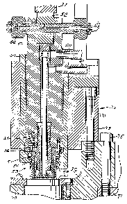
Referring to FIGS. 1-3, the apparatus embodying the
invention comprises a base 30 on which a column 31 is fixed.
A carousel or turret 32 is rotatably mounted on column 31 by
upper and lower bearings 33, 34. The turret 32 supports sets
of tooling comprising a first or upper assembly 35 of tooling and
a second or lower assembly 36 of tooling circumferentially
spaced about the turret 32 . An annular fixed cam 37 is provided
and is associated with the first assembly 35 of tooling, as
presently described. Each second assembly 36 of tooling further
includes an annular gas manifold 38 that supports a plurality
of circumferentially spaced gas cylinders 39. Piston 40 of gas
cylinder 39 acts against a closure supporting pad 41 in the
lower or second set of tooling 36 through an intermediate member
42 (FIG. 7). The manifold 38 and gas cylinders 39 are charged
with an atmospheric gas, preferably nitrogen, at predetermined
pressure.
Referring to FIGS. 5 and 6, each first assembly 35
of tooling comprises an annular support 50. An actuator 51 is
movable vertically in sugport 50 by engagement with a cam
follower roller 52 on the actuator 51 with cam 37 to move a
liner forming plunger assembly 53 mounted an the actuator 51
downwardly through a fixed strode. A closure engaging sleeve
54 is provided about the liner forming tool 53 and is yieldingly
urged axially outwardly and downwardly by circumferentially
spaced springs 55 engaging pins 56. A flange 57 on the 'tooling
-5-
limits the outward movement by engagement with a flange 58 on
an auter fixed sleeve 59.
Coolant is provided to the interior of the liner
forming plunger 53 and circulated therethrough through inlet
60 and outlet 61 connected, in turn, to a distributor 63 mounted
rotatably in the column 31 and rotated by a gear s4 such that
the distributor and associated hoses, not shown, move with each
set of tooling 35 (FIG. 3).
~teferring to FIGS. 3 and 5, the closwre supporting
pads 41 are mounted in a support ring 70 that, in turn, is
mounted on a radial flange 71 on the turret 32. The support ring
70 is secured to flange 71 by bolts 72. The annular support 50
for the first assemblies 35 is supported on the support ring 70
by bolts 73 (FIGS. 5, 7).
Referring to FIGS. 3 and 6, annular gas manifold 38
is mounted on the underside of support ring 70 by bolts 75. The
gas cylinders 39 are mounted on the gas manifold 38 and extend
into cylindrical openings 76 that extend downwardly. Each gas
cylinder 39 has an annular flange 77 that engages the upper
surface of gas manifold 38 and cooperates therewith to form a
seal. The piston 40 of each cylinder 39 engages an intermediate
member 78 which, in turn, engages the closure support pad 41.
A light spring 79 urges the pad 41 upwardly to facilitate laading
of a closure C in position on the pad 41. A retaining ring 80
held in position by bolts 80a limits 'the upward movement o.f the
pad 41.
as-
Gl
Referring to FIGS. 7-12, gas manifold 38 has an inlet
81 with an associated one-way valve 82 (FIG. 12). The chambers
76a of openings 76 beneath each gas cylinder 38 (FIG. 6) are
interconnected by passages 83-85 to provide a manifold chamber
in the chambers 76a beneath the cylinders. The manifold chamber
is provided with nitrogen at a predetermined high pressure
thereby defining a manifold chamber 76a beneath each gas cylinder
39 which is at the predetermined pressure. The passages 84,
85 provide communication to chamber 76a.
One or more of the chambers 76a can be provided with
a pressure gauge 86 (FIG. 10) or a rupture disk 87 for pressure
relief (FIGS. 8, 9 and 11).
Referring to FIGS. 14A and 14B, cam 37 is positioned
to lower the upper tooling 35 into position by engagement of
the roller 52 on the upper tooling 35 for compressing the liner.
A second cam 85 is provided for engaging a second roller 86 on
actuator 51 (FIG. 5) to lift the upper tooling in order to
facilitate placement and removal of closures on the closure
supporting pads 41.
The closures C are preferably made of plastic such
as polypropylene or polyethylene and comprise a base wall and
a peripheral skirt. A typical closure is such as shown in U.S.
patent application Serial No. 07/920,931 filed July 28, 1992,
incorporated herein by reference.
In operation, charges of molten plastic are fed
successively to each closure C positioned in inverted position
as it is moved through a worm 90 and starwheel 91. The charge
7- t
' ~~~~J~~~
of extrudate of plastic material for forming the liner may be
delivered to each closure when the closure is in any position
either before it enters the turret 32 or after it has entered
the turret 32.
As the closure C is moved b su
y pporting pad 41 between
the first or upper assembly 35 of tooling and the lower assembly
36 of tooling which supports the closure and turret 32 is
rotated, the cam 37 moves the upper tooling 35 downwardly causing
the sleeve 53 to engage the closure C and then move the liner
forming plunger 53 downwardly through a fixed stroke to compress
the charge of plastic into a liner, After the initial compression
of the light spring 79, the control of the forming pressure is
through the predetermined pressure on the piston rod 40 of the
gas cylinder 39.
Inasmuch as the pressure of the gas cylinder 39 is at
a very high pressure, for example, on the order to 850 p.s.i.,
and the amount of movement is very small on the order of 0.020
in., the volume of glass displaced relative to the total volume
of the system is relatively insignificant. The gas volume of
the manifold is thereby substantially constant and the force
generated by each cylinder is substantially constant.
Accordingly, the forming or compression farce on the charge of
plastic is accurately controlled at a predetermined pressure.
After a predetermined portion of the cycle of
application of a very high pressure, the cam 37 has a rise that
allows the upper tool forming plunger 53 to retract sufficiently
to raise the lower support plate 41 until the support plate 41
_8_
21~~;>~~'~
contacts the shoulder and the support pad 51 and is supported
only by the spring 79. During this stage, the molding force
is reduced during the plastic cure.
Furthermore, it is possible to adjust the pressure
in the manifold by increasing or decreasing the pressure through
the inlet valve 81.
Tt can thus be seen that in accordance with the
invention, the control of mold farces within each set of
compression molding tool, is independent of external
compensating means.
The turret or carousel is mounted on heavy duty taper
roller bearings to adequately withstand the cantilevered loading
of the molding force. The gas manifold 38 has cross drillings
83-85 in place to connect all the cylinders 39 to a common
Chamber and to a common charging port for system pressure setting.
The upper tooling ring 50 is attached to the turret
and has bushings to guide each upper tooling assembly 35 in the
form of a cartridge and its associated inner tooling components
as it is actuated downwardly by the cam roller 52 engaging the
upper Cam FIG. 37 (FIGS. 13, 14A and 14S). The inner tooling
components include a spring loaded outer tooling components
including a spring loaded outer sleeve and a directly actuated
inner tooling. The upper tooling Cam 37 is continuous, and with
no moving sections. As the turret 32 rotates, successive sets
of upper tooling are actuated downwardly toward the closure as
it rests on the lower tooling plate, and the outer sleeve engages
the Closure seal ring and begins to compress the springs. The
_9_
~~~~~~~~r
previously introduced extruded pellet in the closure is formed
by the advancing inner plunger 53, and each inner tooling
continues to advance a common fixed stroke. The advancing inner
plunger creates a pressure within the melt, and this in turn
results in a force transmitted to the load plate 41, which then
compresses the spring until the piston rod is engaged. The gas
cylinder 39 resists the force of molding until the preset
limiting force is achieved, whereby the cylinder compresses to
limit the molding force. The inner plunger continues to complete
its fixed stroke, and during this time the mold force remains
at its limiting force as preset by the gas pressure.
To offload the tooling forces after molding, the upper
cam has a rise, for example, of about .040 in., and this allows
the upper tool to retract sufficiently to raise the supporting
pad 41 and the load plate until the intermediate plate '70
contacts the shoulder in the tooling ring, and the tooling plate
is supported only by the spring. Thus during the curing stage,
the molding force is reduced. As indicated above, the
cantilevered load on the turret is opposed by the tapered roller
z0 bearing mount of the turret.
It can thus be seen that there has been provided a
method and apparatus for compression molding liners in plastic
closures wherein the molding pressure on the charge that is
being shaped to define the liner is accurately controlled;
wherein when an 'array of tooling is provided, each set of tooling
functions independently of the other; wherein the forming
-10-
_..
pressure can be readily changed; and wherein the tooling can
be readily assembled and removed.
-1~.-