Sélection de la langue

Search

Sommaire du brevet 2123412 

Énoncé de désistement de responsabilité concernant l'information provenant de tiers

Une partie des informations de ce site Web a été fournie par des sources externes. Le gouvernement du Canada n'assume aucune responsabilité concernant la précision, l'actualité ou la fiabilité des informations fournies par les sources externes. Les utilisateurs qui désirent employer cette information devraient consulter directement la source des informations. Le contenu fourni par les sources externes n'est pas assujetti aux exigences sur les langues officielles, la protection des renseignements personnels et l'accessibilité.

Disponibilité de l'Abrégé et des Revendications

L'apparition de différences dans le texte et l'image des Revendications et de l'Abrégé dépend du moment auquel le document est publié. Les textes des Revendications et de l'Abrégé sont affichés :

  • lorsque la demande peut être examinée par le public;
  • lorsque le brevet est émis (délivrance).
(12) Demande de brevet: (11) CA 2123412
(54) Titre français: BOBINE DE TRANSPORT
(54) Titre anglais: A ROLL CARRIER
Statut: Réputée abandonnée et au-delà du délai pour le rétablissement - en attente de la réponse à l’avis de communication rejetée
Données bibliographiques
(51) Classification internationale des brevets (CIB):
  • B65H 75/24 (2006.01)
  • B65H 75/10 (2006.01)
  • B65H 75/18 (2006.01)
(72) Inventeurs :
  • HAGLEITNER, HANS GEORG (Autriche)
(73) Titulaires :
  • HAGLEITNER BETRIEBSHYGIENE GES.M.B.H. CO. KG
(71) Demandeurs :
  • HAGLEITNER BETRIEBSHYGIENE GES.M.B.H. CO. KG (Autriche)
(74) Agent: SMART & BIGGAR LP
(74) Co-agent:
(45) Délivré:
(86) Date de dépôt PCT: 1992-10-23
(87) Mise à la disponibilité du public: 1993-05-27
Licence disponible: S.O.
Cédé au domaine public: S.O.
(25) Langue des documents déposés: Anglais

Traité de coopération en matière de brevets (PCT): Oui
(86) Numéro de la demande PCT: PCT/AT1992/000131
(87) Numéro de publication internationale PCT: AT1992000131
(85) Entrée nationale: 1994-05-11

(30) Données de priorité de la demande:
Numéro de la demande Pays / territoire Date
91119401.7 (Allemagne) 1991-11-14

Abrégés

Abrégé anglais


(57) Abstract
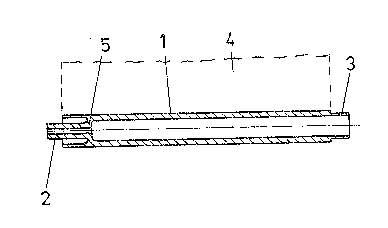
Described is a reel designed as a core on whose
curved surface (1) a strip of material, in particular pa-
per. can be wound The ends of the reel have coupling
elements (2, 3) by which the reel can be connected to
a winding drive as well as to another reel. Several
reels can be fitted together to produce a core on
which several strips of material (4) can be wound si-
multaneously. On completion of the winding opera-
tion, the rolls of material can be separated from each
other, the coupling elements (2, 3) forming trunnions
which project out along the longitudinal axis of the
reel.

Revendications

Note : Les revendications sont présentées dans la langue officielle dans laquelle elles ont été soumises.


WO 93/10033 -5 - PCT/AT92/00131
PATENT CLAIMS
1. A roll carrier, on the peripheral surface of which a web (4)
of material can be wound and which at the ends incorporates
coupling elements (2, 3) to provide a connection with a
winding drive system, characterized in that the end coupling
elements (2, 3) are so formed that a plurality of roll
carriers can be assembled to form a winding core that winds
a plurality of bands (4) of material simultaneously.
2. A roll carrier as defined in claim 1, characterized in that
both coupling elements (2, 3) project axially beyond the
periphery (1) and form bearing journals.
3. A roll carrier as defined in claim 1 or claim 2,
characterized in that the coupling elements (2, 3) are
formed in different ways.
4. A roll carrier as defined in one of the claims 1 to 3,
characterized in that at least one coupling element (2, 3)
incorporates spring detent elements.

Description

Note : Les descriptions sont présentées dans la langue officielle dans laquelle elles ont été soumises.

2 1 `~ 2
wo 93/10033 FILE, P~ N ~ ,r.~ FJL ~ PCT/AT92/00131
T-~ TRANS!. `~ i 10
23739-293
A ROLL CARRIER
The present invention relates to a roll carrier, on the
peripheral surface of which a band of material can be wound and
which incorporates coupling elements at its ends, these being
used to connect it to a winder drive system.
Such a roll carrier i5 described, for example, in US-A 4,754,537. ~:
An end cap is inserted in both ends of a tube and this end cap
incorporates a rectangular [square] opening to connect it to a
drive shaft. The roll carrier is intended, in particular, for
textiles and, for this reason, is very long, ~or example, two
meters long. ;
I~ it is intended to wind bands o~ material that are of lesser
width, for example, toilet paper or the like, usually a cardboard
sleeve, the length of which is a multiple of its subsequent
length, is slid onto a driven winder core or mandrel of a winding
machine and fixed in position, in particular by being braced in
position. Relatively complicated mechanisms to do this are
known. The roll carrier that has a plurality of bands of
material wound onto it is then released ~rom the winding core, i--
drawn off the core and cut to the requirad lengths. As soon as
the material band that has been wound onto the cores has been
used up, the empty cardboard sleeve is discarded. The cardboard
sleeve itself is wound up from a plurality of layers of paper.
Thus, all in all, this r~sults in a relatively costly, and labour
and cost-intensive manufacturing process, both for the roll
carrler and for the rolls that are produced.
Xt is the task of the present invention to eliminate this
disadvantage, and to this end it proposes that a roll carrier, in

-"` 2~23 1~2
wo 93/10033 ~~ ~ PCT/AT92/00131
which the end coupling elements are so formed that a number of
roll carriers can be combined to form a winding core that winds a
plurality of bands of material simultaneously, be used for narrow
bands of material such as toilet paper or the like. This means
that the former cardboard sleeves nePd not be used and the
connecting system between the winding cores and the roll carriers
becomes unnecessary. After removal of the winding core from the
winding device, the individual rolls can be separated from each
other. The roll carrier according to the present invention is
made, in particular, from plastic, for example, by injection
moulding, so that the coupling elements that are required to
establish the necessary connections and to connect the roll
carrier to the drive system can be moulded in place at the same
time. This makes it possible to achieve a smaller roll carrier
diameter than is possible using wound-up cardboard sleeves, so
that a significantly longer strip of material can be accommodated
on the same roll diameter. Depending on the value of the
material used for the roll carrier, when the strip of material
has been used up, this can be discarded, although it is preferred
that it be returned for re-use.
Very o~ten, dispensers are used in which at least two such rolls
can he accommodated, in the case of rolls o~ toilet paper, rolls
of paper towels, household rolls, rolls of plastic or metal foil
such as are used for domestic purposes, and for rolls of bags,
and the like. After the first roll has been used up, a second is
available for use, and this slips down guides into the dispensing "
position. A preferred embodiment that is suitable for this
purpose is such that both coupling elements extend axially beyond
the periphery and form guide or bearing journals. Using the
rolls in this type of dispenser also makes it simpler to collect
the empty roll carriers for re-use, for they can be collected in
a storage area within the dispenser. They are joined together

3'1~
Wo 93/10033 -3 ~ PCT/AT92/00131
and installed once again on the drive system of the winding
device as winding cores.
Another embodiment is such that at least one coupling element has
spring-type detent elements.
The present invention will be described in greater detail below
on the basis of the drawings appended hereto, without being
restricted to these. These drawings show the following:
Figure 1: a first embodiment of a roll carrier, in longitudinal i~
section;
Figure 2: a winding core made up of a plurality of roll carriers
as in figure 1, also in longitudinal section;
Figure 3: a secand embodiment of a roll carrier, in longitudinal
section;
Figure 4: a cross-section on the line IV-IV in figure 3;
Figure 5: an end view of the roll carriex as viewed in the
direction indicated by the arrow A in figure 3.
A roll carrier, particularly one that is injection-moulded from
plastic and which can be used as a winding core, has a middle
section on the peripheral section 1 of which a strip 4 of
material can be wound. A coupling element 2, 3 extends from both
ends and of these at least one, for example the coupling element
2, can be connected to a winding drive system.
As is shown in figures 1 and 2, a coupling element is formed by a
journal 2: this protrudes from an inner intermediate wall 5 of
the sleeve-like roll carrier so as to leave an annular gap
between it and the peripheral wall. This journal is of small
diameter. The journal 2 is, for example, formed so as to ba non-
circular or provided with a dog in the peripheral direction so as
to achieve a positive fit with a winding drive system (not sho~n

`" 2~23~
Wo 93/10033 ~4 ~ PCT/AT92/00131
herein) in the peripheral direction. The second coupling element
is in the form of a hollow journal 3, the diameter and wall
thickness of whlch correspond to the annular gap in the first
coupling element. As figure 2 shows, despite the projection on
both ends, this results in a close fitting arrangement of the
peripheral surfaces 1 of the roll carriers that have been
combined, with, in each instance, a journal ~ fitting into a
hollow journal 3. A plurality of bands 4 of material can be
wound simultaneously on a winding core formed in this way, said
bands resulting, for example, from cutting up a wide strip. As
soon as the rolls have been wound, the winding core is taken off
the winding drive system, when the individual rolls or roll
carriers can be withdrawn from each other. When this is done, at
least some of the coupling elements 2, 3 extend axially beyond
the roll and these can then be used as the bearing journals for --~
the roll in a dispenser.
,.,
In the embodiment shown in figures 3 to 5, the coupling elements
2, 3 snap into each other. To this end, windows 6 are formed in
the end areas of the peripheral wall that support the journals 2
and the hollow journal 3 incorporates two spring detent tabs 7
that are separated by slots 8; when the roller carriers are
assembled these detent tabs 7 snap into the windows 6. The
detent tabs 7 have an outer surface that rises to one side so
that there is a positive fit only in the direction of rotation
during the winding process, but no such positive fit in the
opposite direction. Thus, the roll carriers can be separated
from each other very easily by rotation.
The coupling elements 2, ~ can be formed in a similar manner so
that they can be assembled as desired. Thus, it is possible to
provide the face ends with dogs that fit into each other axially.
'

Dessin représentatif
Une figure unique qui représente un dessin illustrant l'invention.
États administratifs

2024-08-01 : Dans le cadre de la transition vers les Brevets de nouvelle génération (BNG), la base de données sur les brevets canadiens (BDBC) contient désormais un Historique d'événement plus détaillé, qui reproduit le Journal des événements de notre nouvelle solution interne.

Veuillez noter que les événements débutant par « Inactive : » se réfèrent à des événements qui ne sont plus utilisés dans notre nouvelle solution interne.

Pour une meilleure compréhension de l'état de la demande ou brevet qui figure sur cette page, la rubrique Mise en garde , et les descriptions de Brevet , Historique d'événement , Taxes périodiques et Historique des paiements devraient être consultées.

Historique d'événement

Description Date
Inactive : CIB de MCD 2006-03-11
Le délai pour l'annulation est expiré 1997-10-23
Demande non rétablie avant l'échéance 1997-10-23
Réputée abandonnée - omission de répondre à un avis sur les taxes pour le maintien en état 1996-10-23
Demande publiée (accessible au public) 1993-05-27

Historique d'abandonnement

Date d'abandonnement Raison Date de rétablissement
1996-10-23
Titulaires au dossier

Les titulaires actuels et antérieures au dossier sont affichés en ordre alphabétique.

Titulaires actuels au dossier
HAGLEITNER BETRIEBSHYGIENE GES.M.B.H. CO. KG
Titulaires antérieures au dossier
HANS GEORG HAGLEITNER
Les propriétaires antérieurs qui ne figurent pas dans la liste des « Propriétaires au dossier » apparaîtront dans d'autres documents au dossier.
Documents

Pour visionner les fichiers sélectionnés, entrer le code reCAPTCHA :


Pour visualiser une image, cliquer sur un lien dans la colonne description du document (Temporairement non-disponible). Pour télécharger l'image (les images), cliquer l'une ou plusieurs cases à cocher dans la première colonne et ensuite cliquer sur le bouton "Télécharger sélection en format PDF (archive Zip)" ou le bouton "Télécharger sélection (en un fichier PDF fusionné)".

Liste des documents de brevet publiés et non publiés sur la BDBC .

Si vous avez des difficultés à accéder au contenu, veuillez communiquer avec le Centre de services à la clientèle au 1-866-997-1936, ou envoyer un courriel au Centre de service à la clientèle de l'OPIC.

({010=Tous les documents, 020=Au moment du dépôt, 030=Au moment de la mise à la disponibilité du public, 040=À la délivrance, 050=Examen, 060=Correspondance reçue, 070=Divers, 080=Correspondance envoyée, 090=Paiement})


Description du
Document 
Date
(aaaa-mm-jj) 
Nombre de pages   Taille de l'image (Ko) 
Abrégé 1993-05-26 1 43
Dessins 1993-05-26 2 93
Revendications 1993-05-26 1 52
Description 1993-05-26 4 277
Dessin représentatif 1999-05-17 1 6
Taxes 1995-09-26 1 48
Taxes 1994-09-28 1 38
Rapport d'examen préliminaire international 1994-05-10 28 780