Note : Les descriptions sont présentées dans la langue officielle dans laquelle elles ont été soumises.
W 0 93/09872 ~ Q :I PCTJNL92/002t~
Test device comDrisin~ a Dlate containin~ a multiDlicitv of wells with ~n
associated meterin~ devi~e. as well as a kit wh_cn comD-i~es these devices
and use of the devices.
The present invention relates to a test device comprising a plste
5 containing a multiplicity of wells. The invention also relstes to a
metering device suitable for the simultaneous introduction of equal volumes
of reagent into different wells of the test device. In addition, the inven-
tion relates to a method for carrying out a (bio- and/or immuno) chemical
test using the test device and/or the metering device and the invention is
10 aimed at a kit which comprises the test device and the metering device.
A test device comprising a plate containing a multiplicity of wells
has already been known for years in the form of the so-called microtitre
plate. m e known oicrotitre plate i6 of the order of 12.5 cm x 8.0 cm in
size and compri6es 96 wells. The diameter of each well is about 0.6 cm and
the depth of each well is about 1.0 cm, 60 that each well c~n contain at
most a 250 ~1 sample. The wells are ~eparated by material barriers with a
width of approxi-ately 2.0 m.
The known microtitre plate is used when carrying out diverse bio-
and/or immunochemical tests. In tests of this type, photometric detection
20 is frequently used. A very well-known example of such a test is the ELISA.
In the case of photometric determinations, the bottom of a well must be
uniformly covered with a layer of the sample to be analysed in order to
obtain reliable results. Furthermore, this layer must have a thickness
which is at least such that detectable absorption occurs. In practice, this
25 generally implies that samples are used which have at least a volume of
50 ul.
Since bio- and/or immunochemical tests frequently involve large
numbers of tests on samples (such as blood and sera) which have to be
obtained from test persons and/or animals, there is a need to use as little
30 sample as possible per test.
However, the sample can be diluted to only a limited degree since
the component to be analysed must also be present in the well in B certain
minimum concentration in order to obtain measurable absorption. This is
because, according to Lambert-Beers' law, the light intensity is dependent
35 on the concentration and the absorption coefficient of the cooponent to be
analysed and slso on the distance the light has to travel through the
sample to be measured. In practice, this implies the use of about 12.5 ml
W O 93/09872 2 1 2 3 ~ a ~ PCT/NL92/00213
-- 2
of reagents per microtitre plste. In sueh csses there is ~n apprecia~le
need to reduce the amount of sample to be used.
Another frequent use of the current microtitre pl~te is in the
synthesis of peptides. In such syntheses peptides containing different
5 smino acid sequences can be synthesised. This can be carried out, for
ex~mple, with a view to determining the location of an epitope of a protein
for a specific antibody. To this end, peptides containing amino ~cid
sequences corresponding to ~ fragment of the protein to be studied are
synthesi~ed separately. The synthesis can be carried out in such a way that
lO each peptide in part contains the amino acid sequence of another peptide.
It i8 even possible to carry out the synthesis in such a way that only one
amino acid does not overlap. It i8 also possible to produce a series of
short 6ections, for example hexapeptides which overlap with the exception
of one amino acid. A determination is then carried out to establish with
15 which peptide antibody binding takes place. Peptides with which antibody
binding takes place contain an epitope.
In the first in6tsnce, peptide synthesi6 was carried out by add'ing
the amino acid to be coupled to the well of the known microtitre plate in
which the peptide had to be synthe6i6ed, then coupling the de6ired emino
20 acid to the growing peptide chain, subsequently washing the well to remove
any unreacted amino acid and repeating the procedure with the next amino
acid.
However, with this method problems were experienced in rinsing the
wells and, therefore, a method of peptide synthesis was adopted in which
25 small polyethylene rods are used as 6upports for the growing peptide
chains. This method is described by Geysen, H.M., Meloen, R.H. and Barte-
ling, S.J. beschreven in Proc. Natl. Acad. Sci. USA, Vol. ôl ~July 1984)
pp. 3998-4002. In this article, a method is described for the simultaneous
6ynthesis of hundreds of peptides on a solid 6upport with adequate purity
for carrying out an ELISA. Interaction of the peptides with antibodies cAn
be detected simply, without removing the peptides from the 6upport. Conse-
guently, it becomes possible to determine an immunogenic epitope with a
good resolution. This method is ~ermed the PEPSCAN.
With this method, the growing peptide chains are allowed to adhere
to polyethylene rods (having B diameter of 4 mm snd a length of 40 ~m) and
the reactions required for peptide synthesis are then carried out using the
ends of the ~upport rods. To this end, the polyethylene rods are first
immer6ed in a 6 percent solution of acrylic acid in water and subjected to
y-radiation. For the subsequent reactions, the ends of the rods are then
W 0 93/09872 21 ~38~ I PCT/NL92/0021~
brought into contsct with B Teflon plate containing a mstrix of wells
corresponding to the locstion of the rods (the known microtitre plste). The
conventionsl methods for peptide chemistry in the solid phase can be used
here, for example for coupling N~-t-butyloxycsrbonyl-L-ly~ine methyl ester
to polyethylene/polyscrylic scid via the NC-amino group of the side chsin.
t(Erickson, B.W. and Merrifield, R.B. (1976) in The Proteins, Eds. Neurath,
H & Hill, R.L. (Academic, New York), Vol. 2, pp. 255-527) and (Meienhofer,
J. (1973) in Hormonal Proteins and Peptides, Ed. Li, C.H., (Academic,
New York), Vol. 2, pp. 45-267)]. After removing the t-butyloxycarbonyl
10 group, t-butyloxycsrbonyl-L-alanine can be coupled, a peptide-like spacer
being formed. The desired amino acids can be coupled ~ucce~sively and,
following the final desired coupling reaction and sfter re oval of the
protecting t-butyloxycarbonyl group, the terminal amino acid can be
acety~ated using acetic anhydride in dimethylformamide/triethylamine. All
coupling reactions carried out with N,N-dicyclohexylcarbodiimide can be
carried out in dimethylformamide in the presence of N-hydroxybenzotriazole.
Any protective groups in side chains of amino acids used in the peptide
synthesis can also be removed. Before the synthesised peptides are examined
further, for example by eans of ELISA, the rods can be washed with a
20 phosphate-buffered saline solution.
Another use of peptide synthesis takes place if one or more ~mino
acids of a known epitope are changed in order to determine which other
sequences are able to function as an epitope and/or in order to determine
which amino acids are essential for the epitope action. A ethod of this
type is described by Geysen, H.M., Meloen, R.H. and Barteling, S.J. in
Proc. Natl. Acad. Sci. USA, Vol. 82 (January 1985) pp. 178-182.
As such methods frequently comprise a large number of syntheses and
thus also the use of large amounts of reagents, which reagents, moreover,
are frequently expensive, there i6 also a need, with a view to reducing
30 costs, to use sample amounts which are as small as possible. Possibilities
hsve therefore been sought for miniaturisation of ~uch peptide syntheses.
A method for miniaturised peptide synthesis has recently been
described in an article by Fodor, S.P.A. et al. (Science, (15 February
1991) pp. 767-773). In this method light is used to control the simulta-
35 neous synthesis of a large number of different chemical compounds. Syn-
thesis takes place on a solid support, such as a glass plate. The support
is 8minated by treatnent with 0.1 % aminopr~opyltriethoxysilane in 95 %
ethanol. Here, a light-sensitive protective group is then introduced, said
protective group disappearing following irradiation with light and giving
W O 93/09872 PCT/NL92/0021~
2123801 - 4 -
B reactive site to which a building block, Rueh as an amino acid, can ve
coupled. The pattern in which exposure to light or other forms of energy
takes place (for example via a ask) determines which areas of the support
are activated for chemical coupling. The entire surface is brought into
5 contact with the building block to be coupled (said building block also
being provided with a light-sensitive protective group). A coupling
reaction will occur only at sites where the light in the previous step has
given rise to activation. The substrate is then exposed through another
mask, so that a subsequent building block can be incorporsted in the
lO desired site. The pattern of the mask and the 6equence of the reagents
determine the sequences of the peptides formed. A high degree of miniaturi-
sation can be schieved in this way. For example, it is possible to synthe-
sise 40,000 different peptides on l cm2.
However, this method has a number of disadvantQges. The removal of
15 the protective light-sensitive group (nitroveratryloxycarbonyl i6 named in
the article) takes place by irradiation for 20 minutes with a mercury lamp
having a power of 12 mWtcm3. This will result in a very long synthesis time
in the case of the synthesis of longer peptides. Furthermore, a different
ma3k will have to be used for each addition step and a different set of
20 masks will have to be used for each series of peptides.
Moreover, only one building block can be added in each addition step
because the various peptides to be synthesised are not spatially separated.
It is obvious that mixing of reagents would otherwise take place and, thus,
undesired products would also form. This ethod is therefore very labori-
25 ous, especially for the synthesis of peptides which differ not only inrespect of length but also in respect of sequence.
The authors of the article themselves also touch on the problem of
the reliability of the ~ynthesis. Deletions can occur as a consequence of
incomplete removal of the protective group, following irradiation with
30 light. The net coupling percentage is 85-95 X. Furthermore, when changing
masks, a certain overlap between the diverse synthesis regions will take
place because of light diffraction, internal reflection and scattering.
Consequently, compounds will be ~ormed in regions which are considered to
be dark, as a result of which undesired insertion of a specific amino acid
35 can take place.
The present invention relates to a test device which solves the
ministuris~tion problems described above and is suitable for use for bio-
and/or immunochemical tests such as ELISA and tests in which peptide
syntheses are used, for example the PEPSCAN as described above.
W O 93/09872 PCT/NL92/0021
~ 5 ~ 2 1 2 ~ g ~ i~
The pre6ent invention relates to a te6t device which comprises ~
plate containing a multiplicity of wells, which i6 characteri6ed in that
the wells have a volume within the range of 0.1-20 ~l. The dimensions of
the well6 will be chosen depending on the price and availability of the
5 ssmples and reagents to be used. In genersl, wells which are as 6mall as
po6sible will be preferred and, therefore, the present invention preferably
relates to a test device in which the wells have a volume within the range
of 0.1-5 ~
Entirely contrary to expectations, it has now been found that making
10 the wells sDaller has no sdverse consequences for the efficient rinsability
thereof. It has been found that the rinsing times required in order to
obtain good rinsing are shortest if the ratio between the depth of the
wells and the diameter thereof is less than 1:1. Therefore, a test device
comprising a plate containing a multiplicity of wells, characterised in
15 that the wells have a volume within the range of 0.1-20 ~l, and that the
ratio between the depth of the wells and the diameter thereof is less than
1:1, is very suitable. A test device according to the invention for which
the ratio between the depth of the wells and the diameter thereof is le~s
than 2:3 is preferred.
Figures 1 and 2 show the results of tests in which the rinsability
of various test devices was investigated. The test devices had wells of
egual diameter (2 mm) but of different depths. The rinsability was investi-
gated on a shsking machine at speeds of, 47 and 40, respectively. The depth
of the well in mm is plotted against the time in minutes needed to properly
25 rinse the well.
The invention is preferably aimed at a test device in which the
wells have a diameter of 1.0-4.0 mm, a diameter of 1.0-2.0 mm being
preferred. The choice of the dimensions of the wells will depend on the
desired specific test for which the test device is to be used. The smaller
30 the diameter, the smaller the required volume of the sample.
In connection with the desired good rinsability, it is also prefer-
red that the wells have a shape 6uch that a vertical cross section of the
wells is essentially U-shsped, the trsnsition between less and base of the
U being gradual. Preferably there are no sharp angles in the well.
A number of suitable shapes of wells are ~hown in Figure 3.
The U shape in which the angle between base ~nd legs is perpendicu-
lar is preferred for photometric determinations in which easurement is
carried out under and through the plate.
, ~
W O 93/09872 21 ~ l PCT/NL92/0021
- 6 -
The test device sccording to the invention will preferably b~
plate containing wells sepHrsted by material b~rriers with a width of 1.0-
5.0 mm, preferably by material barriers with a width between 1.0 and
2.0 mm. The m~terial barriers must be sufficiently wide to prevent reagents
flowing over from one well to another. Specifically, the material barriers
must be 6ufficiently wide when DMF is used as solvent, a6 is frequently the
case in peptide synthesis. This is because DMF is known to have a high
creeping capacity.
The test device according to the invention will comprise a plate
10 containing 5-20 wells per cm2, preferably 10-15 wells per cm2.
Furthermore, the test device will comprise material to which
peptides, proteins and other biochemical molecules, 6uch as hormones and
polysaccharides, are able to adhere. For test devices suitable foi tests
with peptide synthesis, such material will preferably be aterial to which
15 peptides and proteins are able to adhere, such as polyethylene or poly-
6tyrene.
Other suitable examples of materials which can be u6ed in a test
device according to the invention are polypropylene and polycarbonate.
The choice of the materisl for the test device will also depend on
20 the reagents to be used in 6uch a test device and on the detection method.
In the case of photometric analysis through the bottom of the test device,
for example, at least the bottom of the wells will have to be composed of
transparent material. In the case of tests where DMF is used as solvent, it
will not be possible to use a polystyrene test device because DMF is too
25 agOEessive.
A preferred embodiment of the test device will be provided with a
means for recording information, for example a bar code or a magnetic
strip. The test device can be provided with data relating to the test it is
intended to carry out, or which has been carried out, such data for example
30 relating to reagents or samples which have been used. The test device can
also be provided with markings which indicate the coordinations of wells in
the test device.
Figure 4 shows a top view of an example of one embodiment of the
test device according to the invention.
A cross section is shown in Figure 5.
As already mentioned in the preamble, the present invention is also
- aimed at a method for carrying out (bio- and/or immuno)chemical tests, in
which a test device according to the invention is used. In general, a test
device according to the invention can be used in the same tests as the
:
W ~ 93/09872 - 7 _ 2 ~ 2 3 ~3~ ~ PCT/NL92/0021~
known microtitre plate. It is now possible to carry out existing methods
using much smaller amounts of sample and reagents; so-called mini-tests are
now possible. It is possible to reduce the amount of sample used by a
factor of one hundred. It i8 now possible to use 2.5 ~l instead of 250 ~ul
5 ~amples per well. Use of the test device sccording to the invention now
akes mass screening of population groups much more attractive because much
less blood is required from the donor and much smaller quantities of
reagents are required.
Another grest advantage of the miniaturi~ation of the methods by use
lO of the test device according to the invention lies in the fact thst the
existing chemistry does not have to be modified. In this context consider
the great advantage, for example. in the case of sutomated processes, such
as the PEPSCAN. The test device is particularly suitable for use in methods
in which large numbers of samples have to be used. A mini-ELISA and mini-
15 PEPSCAN in which a test device according to the invention is used aresuitable examples of the method according to the present invention. The
advantage of a mini-method according to the invention is that the test can
be carried out with s~mple amounts of less than 20 ul. It is re~dily pos6i-
ble to use sample amounts of less than 5 ~l in a mini-method according to
20 the invention.
The present invention is also aimed at a metering device suitable
for simultaneously introducing egual volumes of reagent into different
wells in a test device according to the invention. A metering device
according to the invention can be used in order to carry out as efficiently
as possible immuno- and/or biochemical tests in which a test device
according to the invention is used. In this context, consideration is given
to optional automation of certain methods according to the invention.
If a predetermined equal ~mount of reagent has to be introduced
simultaneously into a number of wells, it is possible to use a metering
30 device according to the invention, said device being provided wi~h projec-
tions having dimensions and mutual spacings such that individual projec-
tions can simultaneously be positioned in or above wells of a test device
according to the invention. With a metering device of this type, all wells
can simultaneously be provided with equal volumes of reagent if the posi-
tion of the projections is such that this essentially corresponds to theposition of the wells in the test device according to the invention.
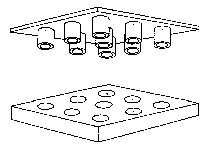
One embodiment of the metering device and the test device is shown
in Figure 6.
W O 93/09872 212 ~ 8 0 ~ - 8 - PCT/NL92/0021~
If not all, but only a certain number, of well6 in the test devlce
have to be filled, B metering device cHn be used which has projections
which simultaneously can be positioned above or in the selected wells.
In Figure 7 the darker wells are the selected well~. The projections
5 of the metering device are located on the metering device in such a way
that they can simultaneously be positioned above or in the darker wells.
To this end, a metering device c~n sdvantageously be used in which
the projections are fixed to the support or can be fixed in a pattern which
corresponds to the pattern of the wells into which reagent has to be intro-
10 duced.
Figure 8 shows an exa~ple of an embodiment of the etering devicein which the projections can be fixed to a 6upport.
The etering device can comprise projections which are fixed or can
be fixed to a support in a way equivalent to the bristles of a brush
(Figs. 6, 7 and 8).
A metering device in which the projections, like the teeth of a
comb, are parallel to one another and are fixed (Fig. 9) or can be fixed
(Fig. lOj at their tops to a support is also an embodiment Or a oetering
device according to the invention which is very suitable. The number of
20 projections can be less than or equal to the number of wells for~ing a row
in the longitudinal direction of the test device. The number of projections
can be less than or equ~l to the number of wells forming a row in the
wid~hwise direction of the test device. The number of projections will
depend on the pattern Or wells of the test device into which reagent has to
25 be introduced.
The projections of a metering device according to the invention can
be integral with the support or can be detachsble. The projections can be
fitted on the support in such a way thst the projections form a pattern
which corresponds to the pattern of wells which have to be filled in the
30 test device (~ee Fig. 7).
It is also possible to use a metering device in which more than one
projection can be positioned above or in a well at the same time, if it is
desired to simultaneously introduce more than one reagent unit, which is
present on a projection, into a well.
Figure 11 shows a metering device in which two projections can be
positioned simultaneously sbove or in each well.
Thus, the amount of reagent which is present on a projection can be
t~ken as standard snd etering devices can be used which have a group of
projections above or in the well, depending on the ratio in which it is
W O 93/09872 212 3 ~ O ~ PC~r/NL92/002t~ ~
_ g _
de6ired to introduce resgent~ into a well. A group will comprise the number
of projections which corresponds to the number of desired reagent units.
In ~he case of a metering device according to the invention, the
projections can be hollow, but they can also be solid or closed at the
5 bottom. The latter two possibilities are to be preferred when working with
very small amounts of sample and reagents, because it is then possible to
work with drops of reagent.
The present invention is also aimed at a method for carrying out a
(bio- snd/or immuno-)chemical test using B metering device according to the
10 invention, in which method
a) the projections of the metering device are provided with reagent,
in 6uch a way that essentially egual volumes of reagent are present
on or in the individual projections of the metering device, and
b) the metering device is then positioned in or above wells of the
test device according to the invention, which wells are intended to
be provided with reagent, each individual projection being located
in or above a well at the same time, snd
c) essentially egual volumes of reagent are introduced into the
individual wells of the test device, which wells it is intended to
provide with reagent.
The invention also relates to a method of this type in which the
projections of the meterin~ device are simultaneously provided with reagent
by immersing the projections in reagent.
The present invention is also aimed at a kit which comprises st
25 least a test device and metering device according to the invention. Such a
kit can comprise a number of metering devices in the various embodiments
described above and can also comprise replaceable projections for such
metering devices.
W 0 93~09872 ~ 12 ~ ~ O l - Io PCT/NL92/0021~
ExamDle 1
Miniaturised Demtide svnthesis
Miniaturised synthesis of a complete tripeptide net (8000 different
peptides) was csrried out using test devices according to the invention.
5 The test device used in this example resembled H credit card in size and
was constructed 60 thst it comprised 455 wells with a diameter of 2 mm and
8 maximum volume of 5 ~ul each. The test device was made of polyethylene. In
order to make this solid carrier suitable for peptide synthesis the wells
were treated via the method described by Geysen et al. (1984) previously
10 mentioned. The carboxyl groups of the polyacrylic acid were provided with
a NH2-group via a linking reaction of a linker t-ButylOxyCarbonyl-HexaMethy-
leneDiAmine (BOC-HMDA) in the presence of N,N-DicyclohexylCarbodiimide and
N-HydrOxyBenzotriazole (DDC/HOBt). All these linking reactions were carried
out in DiMethylFormamide (DMF).
15 _ After removing the t-butyloxycarbonyl group with TriFluor Acetic
acid (TFA) a mixture of all twenty L-~mino acids linked using the ~ame
method as used for linking the linker was used.
The totsl volume used in the linking reaction amounted to 3 ~1 for
each well. Pipetting the required small amounts was ~chieved completely
20 automatically using a computer directed robot arm with a pipette installs-
tion (Hamilton MicroLab 2200). A special software program was written for
this objective enabling two of test devices according to the invention
described in this example to be filled per hour.
The linking time for each amino scid amounted to approximstely 2 to
25 3 hours. The difference in linking time is caused by the reaction stopping
when the reaction mixture has completely evsporated.
Subsequently after removal of the BOC-group with TFA the next amino
acid was linked in the same manner after which the cycle was repeated twice
more.
After the last linkage reaction and after removal of the BOC-group
the terminal NH2-group was acetylated with a mixture of acetic acid anhy-
dride in DMF and TriEthylAmine in the ratio 2/5/1. The groups protecting
the side groups were removed in a strong acid environment. In this instance
BoriumTrisTrifluor acetic acid (BTT) in TFA (30 mg/ml) was used for two
35 hours at room temperature.
The total structure of the peptide was as follows:
Ac-A3-A2-AI -X-carrier,
~ wherein Ac represents an acetyl group. A~ represents a single amino acid and
;~ X represents the mixture of amino acids.
W 0 93/09872 212 3 ~ o ~ PCT/NL9Z/WZl~
Exam~le 2
~lisa
The test devices according to the invention were rinsed with phos-
phate buffered saline (PBS, 3xlO min) before incubation of the peptides
5 with serum, after which the test devices according to the invention were
precoated for 1 hour at 37-C with 10% horse serum/10% ovalbumlne/1% Tween
80 in PBS (SuperQ) in order to prevent aspecific absorption of sntibodies.
The test devices according to the invention were completely submerged in
the liquid.
Filling the test device wells with serum dilution can be carried out
in two ways. If only a little serum is available the test devices can be
filled using the robot arm mentioned in the previous example and when
sufficient serum is available the test devices can be submerged in the
serum and subsequently be wiped so that all the well6 are s~multaneously
filled.
Incubation of the test devices took place during the night at 4-C
in air saturated with water, after which the test devices were washed three
times with 0.05X Tween 80/PBS in order to remove antibodies that had not
been bound. The test device6 according to the invention that had been
20 incubated with serum were subsequently incubated for 1 hour at 37-C with an
antibody conjugated peroxidase enzyme (1/1000 solution in SuperQ) by
subGerging the test devices in a solution comprising said enzyme. After
this the test devices were rinsed with PBS, 3x 10 min. The presence of the
second antibody was demonstrated with the substrate liguid ABTS (2,2'-
25 Azine-di[3-et~yl benzthiazoline sulfonate (6)]). In this instance it is
also possible to use the two aforementioned methods to fill the wells,
either using the robot arm or submerging the devices in the substrate.