Note : Les descriptions sont présentées dans la langue officielle dans laquelle elles ont été soumises.
.~12~00
-
ILLU~T~D FOOTWEAR
FIELD OF THE INVENTION
The present invention relates to illuminated
footwear and, more particularly to footwear where the
illumination is activated when the wearer applies pressure to
the sole of the footwear when stepping.
BACKGROUND OF THE INVENTION
Illuminated footwear of the type described herein
generally include an electrical circuit encapsulated within
the heel portion of the footwear. The electrical circuit
comprises a light source, a power source, a switch mechanism,
and circuitry. Light emitted from the light source may be
observed outside the shoe as the heel portion of the shoe has
transparent side andlor bottom portions. In this type of
footwear there have been three types of switch mechanisms
which have been used to activate the light source; manual,
pressure sensitive, and motion detection. Pressure sensitive
and motion responsive switches are preferred over manual
switches since they offer intermittent lighting, which in turn
reduces the draw of power from the power source.
Aside from its decorative effects, illuminating
shoes also act as a safety feature when walking or running in
dark or dimly-lit areas. Light coming from the shoe will
alert drivers of the wearer's presence, thereby preventing
possible injury to the wearer.
Generally, this valuable safety feature has been
found In the prior art for some time. However, certain
disadvantages may be seen in how illuminated footwear has been
2l.24lao
designed and constructed in the past. In the case of Canadian
Patent No. l,253,832 and United States Patent No. 5,188,447,
piezoelectric and motion responsive means were deployed to
restrict duration of the light pulses in order to conserve
battery power. This solution may be disadvantageous in
situations where the wearer desires to remain stationary and
yet be seen. Older devices seen in the prior art, while
capable of providing illumination in a stationary position,
are nevertheless cumbersome in construction. Bulky sheet
metals occupying large heel areas restrict the use of these
designs to mainly high heel shoes. More modern designs which
use a pressure sensitive mechanism have taken advantage of the
miniaturisation of electronic components and new materials
used in the construction of soles of shoes. However, there
r~i ns a need to provide an illuminating shoe that is simple
and compact in design, economical to manufacture, and capable
of sustaining illumination in a stationary position while
maximizing the amount of light which is transmitted to the
outside of the shoe.
SUMMARY OF THE INVENTION
It is an object of the present invention to provide
an illuminating footwear capable of sustained illumination in
a stationary position.
It is a further object of the present invention to
provide an such illuminating footwear that is simple and
compact in design, economical to produce, and adaptable to
different types of footwear which utilizes a small light
source and which transmits a m~xim~l amount of light to the
outside of the shoe.
21~4100
According to the present invention, there is
provided illuminated footwear comprising a transparent or
translucent sole insert with a central cavity and a light
circuit contained within said central cavity, said light
circuit being operably switchable between an illuminated
state, when downward pressure is being exerted on the sole of
the shoe and a non illuminated state when downward pressure
is not being exerted on the sole of the shoe.
BRIEF DESCRIPTION OF THE DRAWINGS
Embodiments of the invention will now be described
in greater detail, and will be better understood when read in
conjunction with the following drawings in which:
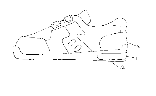
Figure 1 is a side elevational view of a shoe
incorporating one embodiment of the invention;
Figure 2 is a top plan view, partially cut away, of
the insert included in shoe shown in Figure l; and
Figure 3 is a wiring diagram for the circuit of
Figure 2.
DETAILED DESCRIPTION OF THE PREFERRED EMBODIMENTS
With reference to Figure 1, there is shown one
embodiment of the invention incorporating a typical shoe
assembly lO with a transparent or translucent insert 11
disposed on the sole portion 12 of the shoe assembly. The
term translucent will be used in the remainder of this
document as being inclusive of transparent and translucent
materials since it is the light transmitting property of the
-- 3 --
~I ~ J~1~0
material which is important for the purposes of the present
invention. The insert may be formed from suitable materials
such as epoxy derivatives. While Figure 1 illustrates an
insert contained within a shoe, it will be understood that
such an insert may be contained in any form of footwear, such
as boots, overshoes, or slippers.
Figure 2 displays a typical arrangement of light
circuit 13 disposed inside a cavity 20 within insert 14.
Light circuit 13 comprises wires 15 connecting a battery 16,
a contact switch 17, and two light sources 18.
Advantageously, battery 16 contained within light circuit 13
will be a lithium battery, but any lightweight, powerful
battery will suffice. Similarly, light sources 18 will
advantageously be light emitting diodes, but any lightweight,
compact light source would be suitable so long as it is sturdy
enough to withstand the repeated concussions that the sole of
a shoe is exposed to. Contact switch 17 contains contact pad
22 such that when pressure is applied to contact pad 22,
contact switch 17 is closed and circuit 13 is activated.
Light sources 18 will remain illuminated so long as contact
switch 17 is closed.
Cavity 20 is shaped such that circuit 13 will be
held therein in a fixed position with contact pad 22 facing
either upwards towards the insole of shoe 10, or downwards
towards the sole of shoe 10. A layer of felt padding, or
other similar material, can be placed between contact pad 22
and either the sole of shoe 10 or the insole of shoe 10,
depending on whether contact pad 22 faces downward or upward,
respectively. The felt pad assists in transmitting the
downward force exerted when the person wearing shoe 10 takes
a step to contact pad 22, thereby closing switch 17.
-- 4
2,~ n ~
Cavity 20 is additionally shaped such that it
contains a plurality of peripheral channels 34 directed
towards outer edge 40 of shoe 10. Channels 34 are arranged
to receive light sources 18 in a manner that will allow light
sources 18 to come close to the outer edge 40 of shoe 10,
while the structural rigidity of the sole 12 of shoe 10 is
maximised by the regions of the insert 11 between the channels
34. While insert 11 is made of a translucent material, it is
advantageous to have light sources 18 disposed as close as
possible to edge 40 of shoe 10 since the intensity of light
that is transmitted through towards the edge 40 will decrease
as the thickness of material between the end of each channel
36 and the edge 40 increases.
Channels 34 are arranged along the periphery of
cavity 20 such that light is directed towards the rear of shoe
10 and the lateral side of shoe 10. With such an arrangement,
light emitted from the shoe may be viewed from the rear and
to both sides of a person wearing a pair of such shoes 10.
Figure 2 would therefore correspond to a heel insert 11 of a
right shoe with channels 34 directed toward the rear of the
shoe and towards the right side of the heel.
The heel insert 11 of Figure 2 also illustrates that
the number of light sources 18 does not necessarily correspond
to the number of channels 34. While optimal illumination
occurs when a light source 18 is located within or in close
proximity to a channel 34, light is still transmitted from a
remote light source through a channel more easily than it is
through the translucent material of surrounding insert 11.
While Figure 2 displays two light sources 18 and three
channels 34, the precise number of each is a matter of design
~1241 D O
choice, and can be changed to suit different circumstances
depending on the optimal weight of the shoe and how strong the
area around cavity 20 is required to be.
A detailed circuit diagram of the circuit 13 shown
in Figure 2 is illustrated in Figure 3. Positive terminal 50
of battery 16 is connected to one terminal of the contact
switch 17. The second terminal of contact switch 17 is
connected in parallel, to one terminal of the two light
emitting diodes 18a. The second terminal of the two light
emitting diodes 18a are then connected to the negative
terminal 52 of battery 16 to complete the circuit 13.
In operation, when a person is wearing shoe 10
equipped with insert 11 located in the heel, during the course
of walking or running, foot pressure concentrates and shifts
between the ball and the heel of the foot. At times when foot
pressure concentrates on the ball of the foot, contact switch
17 remains open, and no electricity passes through circuit 13.
When pressure shifts to the heel of the foot, it causes
contact switch 17 to close, thereby causing light emitting
diodes 18a to illuminate. Consequently, in the normal course
of walking or running, intermittent light pulses can be
observed from the illuminating shoe.
When the wearer is in a stationary position, there
remains sufficient heel pressure to activate contact switch
17. A continuous light will be observed until such time as
when there is insufficient pressure to activate the switch.
It is also possible for contact switch 17 to be located in an
area of the sole of the shoe other than the heel, so long as
pressure is exerted on contact switch 17 when the shoe's
wearer's foot strikes the ground.