Sélection de la langue

Search

Sommaire du brevet 2124468 

Énoncé de désistement de responsabilité concernant l'information provenant de tiers

Une partie des informations de ce site Web a été fournie par des sources externes. Le gouvernement du Canada n'assume aucune responsabilité concernant la précision, l'actualité ou la fiabilité des informations fournies par les sources externes. Les utilisateurs qui désirent employer cette information devraient consulter directement la source des informations. Le contenu fourni par les sources externes n'est pas assujetti aux exigences sur les langues officielles, la protection des renseignements personnels et l'accessibilité.

Disponibilité de l'Abrégé et des Revendications

L'apparition de différences dans le texte et l'image des Revendications et de l'Abrégé dépend du moment auquel le document est publié. Les textes des Revendications et de l'Abrégé sont affichés :

  • lorsque la demande peut être examinée par le public;
  • lorsque le brevet est émis (délivrance).
(12) Demande de brevet: (11) CA 2124468
(54) Titre français: DISPOSITIF DE REVETEMENT EN CONTINU DE MATERIAU EN NAPPE
(54) Titre anglais: COATING SYSTEM FOR COATING TRAVELING WEBS OF MATERIAL
Statut: Réputée abandonnée et au-delà du délai pour le rétablissement - en attente de la réponse à l’avis de communication rejetée
Données bibliographiques
(51) Classification internationale des brevets (CIB):
  • D21H 23/58 (2006.01)
  • B05C 01/08 (2006.01)
  • B05C 09/04 (2006.01)
(72) Inventeurs :
  • PICHLER, JORG (Allemagne)
  • KUSTERMANN, MARTIN (Allemagne)
  • TREFZ, MICHAEL (Allemagne)
(73) Titulaires :
  • J. M. VOITH GMBH
(71) Demandeurs :
  • J. M. VOITH GMBH (Allemagne)
(74) Agent: GOWLING WLG (CANADA) LLP
(74) Co-agent:
(45) Délivré:
(22) Date de dépôt: 1994-05-27
(41) Mise à la disponibilité du public: 1994-11-28
Licence disponible: S.O.
Cédé au domaine public: S.O.
(25) Langue des documents déposés: Anglais

Traité de coopération en matière de brevets (PCT): Non

(30) Données de priorité de la demande:
Numéro de la demande Pays / territoire Date
P 43 17 657.7 (Allemagne) 1993-05-27

Abrégés

Abrégé anglais


ABSTRACT OF THE DISCLOSURE
The invention concerns a coating system with at least one
web support roll and at least one corresponding metering roll
coordinated with it and having a grooved surface essentially in
peripheral direction or in the form of a threading, for metering
the coating substance in the gap existing between the web support
roll and the metering rolls. A groove forming or groove truing
system can be infed in the operation of the coating system can
be infed onto the metering rolls.

Revendications

Note : Les revendications sont présentées dans la langue officielle dans laquelle elles ont été soumises.


- 5 -
WE CLAIM:
1. A coating system for application of a coating mixture
on a material web, comprising:
at least one web support roll,
at least one metering roll operatively associated with said
web support roll and having an outer surface with a plurality of
grooves extending in a generally circumferential direction, said
web support roll and said metering roll defining a metering gab
therebetween, said metering roll defining a means for metering
the coating mixture into said metering gap; and
a first means for at least one of forming and re-forming
said grooves on said metering roll during operation of said
coating system.
2. The coating system of Claim 1, wherein said first means
comprises a laser beam cutting system.
3. The coating system of Claim 1, wherein said first means
comprises a mechanical groove forming system.
4. The coating system of Claim 3, wherein said first means
comprises a thread rolling system.
5. The coating system of Claim 1, further comprising a
cleaning system operatively associated with said metering roll
for cleaning the surface of said metering roll.
6. The coating system of Claim 5, wherein said cleaning
system is disposed between said metering gap and said first means
on a downstream side of said metering gap.
7. The coating system of Claim 1, wherein said at least
one web support roll comprises two web support rolls defining a
squeeze gap therebetween, said material web transferred through
said squeeze gap for receiving the coating mixture thereat, and
wherein said at least one metering roll comprises two metering
rolls operatively associated with each said web support roll,
respectively, and further comprising a second means for at least
one of forming and re-forming said grooves during operation of
said coating system, each of said first and second means
respectively associated with said two metering rolls.

- 6 -
8. The coating system of Claim 7, further comprising means
connected to each of said first and second means for controlling
movement of said first and second means in a direction
substantially parallel to a longitudinal axis of said each
metering roll, respectively.
9. The coating system of Claim 1, further comprising means
for controlling a position of said first means along said
longitudinal axis of said metering roll.

Description

Note : Les descriptions sont présentées dans la langue officielle dans laquelle elles ont été soumises.

COATING SYSTEM FOR COATING
TRAVELING WEBS OF MATERIAL
The invention relates to a coating system for the coating
of traveling webs of material, notably of paper or cardboard.
As used herein, the term coating system comprises a system
featuring rolls of which at least one is a web ~;upport roll while
another is a metering roll and effects a coating or impregnation
of a traveling paper web with a coating mixture or other coating
or impregnating substance. ~;
EP 0 362 174 A describes a system in which the metering roll
has a cylindrical core and, wound on it in the form of a
threading, a wire with a small diameter, which is stated, e.g.,
to be 0.3 mm. According to the references in this document, the
cylindrical core diameter may be about 300 mm. Small rolls of
reduced diameter and of such structure have so far been used
frequently and are commonly called grooved roll doctors. The
diameter of these so-called roll doctors ranged generally between
10 and 20 mm. A disadvantage of all of these systems is the wear
of the fine wire lashing of the substrate core, both with the
grooved roll doctor and the metering roll provided with a wire
lashing. Such wear occurs particularly in the case of pigmented
coatings. As a result, the necessary constant rate of
application flow is no longer given over the service life of the
grooved metering roll or roll doctor. Namely, as the bulges of
the wires or protuberances forming the grooves wear down, a
reduction occurs of the passage cross section between metering
roll and web support roll, which entails a steady reduction of
the coating weight.
Another disadvantage with the prior art is the occurrence
of a considerable jump in coating weight as a worn metering
system is replaced by a new one. This leads to quality
fluctuations in the finished product, which often cannot be
tolerated. Therefore, the problem underlying the invention is
to reduce the wear of the metering roll or doctor.

:
: ~
- 212~4~8
- 2 -
It is an ob~ect of the present invention to provide a novel
coating system which obviates or mitigates at least one of the
disadvantages of the prior art.
Preferably, the present invention involves a forming or re-
~orming of the metering roll grooves during operation, wherebythe wear is compensated for. This measure is effected
irrespective of the measurement of the momentarily achieved
coating weight, preferably based on wet substance.
To that end it is necessary to no longer use wire-lashed
metering rolls but integral metering rolls, the grooves of which
are machined into their surface. The truing of the grooves can
favorably be accomplished with a laser beam cutting system or
with a groove or thread rolling system. To enable an accurate
opera~ion of such a system, cleaning systems are favorably
allowed to act upon the metering roll sur~ace, with the result
that the groove-forming system works on a clean surface of the
metering roll.
Preferred embodiments of the present invention will now be
described, by way of example only, with reference to the attached
Figures wherein:
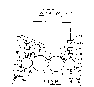
Fig. 1, a side elevational view of an embodiment of the
system of the present invention;
Fig. 2, a plan view of the groove-forming system; and
Fig. 3, a side elevational view of another embodiment of the
prasent invention.
In Fig. 1 there are two web support rolls 1 and 2 with
which metering rolls 3, 4 each, equipped with a grooved shell
surface, are coordinated. The web C proceeds via reversing rolls
27 and 28 into the squeeze gap 12 forming between the two web
support rolls 1 and 2. Together with the met ring rolls 3, 4 the
latter form respective metering gaps 13, 14. The application of
the coating mixture on the shell of the web support rolls 1, 2
is effected by spray or pouring system 5, 5' featuring a rollwide
matering gap. The groove-forming systems coordinated with the
two metering rolls 3 and 4 are only indicated here. TQ clean the
grooves of the metering rolls, a cleaning system 17 each is
- -- : :. , : ~ ....................................... .
~ ~-

2~2~
coordinated with them which, e.g., may employ spray jets and for
which a collection trough 34 each is proved to receive the amount
of coating mixture washed off. The cleaning may be amplified by
an additional brush 19.
The groove-forming system 9, 9' features in this case a
laser beam gun 16 supported by a holder 15 and a lead screw
system 24 which, in turn, is being held by a t:ransport head 25.
The latter head runs on a lead screw 26 along the metering roll.
A pertaining controller 29 is shown in Fig. 1 and the motor is
not illustrated. The lead screw makes it possible to reciprocate
the groove-forming system along the rolls for groove touch-up
during this motion, depending on how heavy a wear, or reduction
o~ groove cross section, has already occurred. To obtain an
accurate stock removal for an accurately controlled increase in
groove depth, the lead screw unit is controlled dependent on a
distance measuring system 30 which measures the spaciny of the
laser beam gun or machining tool in general from the metering
roll respectively its shell surface. The procedure may he such
that a touch-up between 2 and 20 ~m is carried out, matching a
specific wear that has occurred. The truing or re-forming tool,
for instance the laser beam gun, may be so designed that l to 10
or more adjacent profile threads can be processed simultaneously.
Fig. 3 shows a similar system, the direction of roll
rotation and direction of web travel being opposite here to Fig.
1. Provided as applicator is here a dip roll 6 each which dips
into the coating mixture contained in a tub 7. In this cas2, as
indicated, the groove-forming system 9' ' employs a roller 10,
so that the groove-forming system virtually represents a thread
rolling system. Necessary here are means for obtaining a
definitive contact force, which is indicated here by the spring
11. The thread rolling systems are preferably arranged exactly
diametrically opposed and are moved along the rolls in
synchronism.
As such, of course, there are now most varied variants of
the coating system possible which, however, are known extensively
from the prior art. It is possible, of course, to provide only

212~6~
- 4 -
::
'
a single web support roll and to effect the coating of the web
by the so-called drag application, whereas with the systems
presented so far a double-sided application is possible. Only
one side may be coated, of course, while the other side is coated
or impregnated with nonabrasive fluid, which makes the groov~
truing system superfluous on this metering roll. On the other
hand, of course, groove forming systems still other than those
described are possible.
In certain cases, lastly, it is also possible to perform a
certain profiling of the metering rolls across their width when
a varying infeed of the groove forming system is adjusted across
the width of the rolls. ~he procedure could be such that for
instance a hydraulic unit consisting of piston and cylinder could
replace spring system 11 (Figure 3) and be acted upon by an
appropriately variable controlled pressure. In the other case,
i.e., Figure 1, the stroke of the lead screw system would be
controlled appropriately.
While this invention has been described as having a
preferred design, the present invention can be further modified
within the spirit and scope of this disclosure. This application
is therefore intended to cover any variations, uses, or
adaptations of the invention using its general principles.
Further, this application is intended to cover such departures
from the present disclosure as come within known or customary
practice in the art to which this invention pertains and which
fall within the limits of the appended claims.

Dessin représentatif
Une figure unique qui représente un dessin illustrant l'invention.
États administratifs

2024-08-01 : Dans le cadre de la transition vers les Brevets de nouvelle génération (BNG), la base de données sur les brevets canadiens (BDBC) contient désormais un Historique d'événement plus détaillé, qui reproduit le Journal des événements de notre nouvelle solution interne.

Veuillez noter que les événements débutant par « Inactive : » se réfèrent à des événements qui ne sont plus utilisés dans notre nouvelle solution interne.

Pour une meilleure compréhension de l'état de la demande ou brevet qui figure sur cette page, la rubrique Mise en garde , et les descriptions de Brevet , Historique d'événement , Taxes périodiques et Historique des paiements devraient être consultées.

Historique d'événement

Description Date
Inactive : CIB expirée 2014-01-01
Inactive : CIB de MCD 2006-03-11
Inactive : Lettre officielle 1998-07-09
Le délai pour l'annulation est expiré 1998-05-27
Demande non rétablie avant l'échéance 1998-05-27
Demande visant la révocation de la nomination d'un agent 1998-04-03
Demande visant la nomination d'un agent 1998-04-03
Réputée abandonnée - omission de répondre à un avis sur les taxes pour le maintien en état 1997-05-27
Demande publiée (accessible au public) 1994-11-28

Historique d'abandonnement

Date d'abandonnement Raison Date de rétablissement
1997-05-27
Titulaires au dossier

Les titulaires actuels et antérieures au dossier sont affichés en ordre alphabétique.

Titulaires actuels au dossier
J. M. VOITH GMBH
Titulaires antérieures au dossier
JORG PICHLER
MARTIN KUSTERMANN
MICHAEL TREFZ
Les propriétaires antérieurs qui ne figurent pas dans la liste des « Propriétaires au dossier » apparaîtront dans d'autres documents au dossier.
Documents

Pour visionner les fichiers sélectionnés, entrer le code reCAPTCHA :


Pour visualiser une image, cliquer sur un lien dans la colonne description du document. Pour télécharger l'image (les images), cliquer l'une ou plusieurs cases à cocher dans la première colonne et ensuite cliquer sur le bouton "Télécharger sélection en format PDF (archive Zip)" ou le bouton "Télécharger sélection (en un fichier PDF fusionné)".

Liste des documents de brevet publiés et non publiés sur la BDBC .

Si vous avez des difficultés à accéder au contenu, veuillez communiquer avec le Centre de services à la clientèle au 1-866-997-1936, ou envoyer un courriel au Centre de service à la clientèle de l'OPIC.


Description du
Document 
Date
(aaaa-mm-jj) 
Nombre de pages   Taille de l'image (Ko) 
Dessins 1994-11-27 1 26
Revendications 1994-11-27 2 85
Abrégé 1994-11-27 1 21
Description 1994-11-27 4 213
Dessin représentatif 1998-08-02 1 10
Courtoisie - Lettre d'abandon (taxe de maintien en état) 1997-08-18 1 188
Correspondance 1998-07-08 1 6
Correspondance 1998-07-08 1 7
Taxes 1996-04-25 1 47
Courtoisie - Lettre du bureau 1998-07-08 1 21
Courtoisie - Lettre du bureau 1998-07-08 1 19
Correspondance reliée au PCT 1998-04-02 4 102