Note : Les descriptions sont présentées dans la langue officielle dans laquelle elles ont été soumises.
- 1 -
A RADIAL PNEUMATIC LIGHT TRUCK OR AUTOMOBILE TIRE
Backcrround of the Invention
This invention relates to a tread for a pneumatic
tire; more specifically, to a tread for light truck or
automobile type vehicles.
A recent tread design was disclosed relating to a
tread having an aquachannel. U.S. Patent No.
5,176,766 issued January 5, 1993, describes a
directional tire having an annular aquachannel. The
tire is commercially sold under the name Aquatred~.
The above-referenced tire has demonstrated
significant improvements in wet traction and
hydroplaning characteristics.
Interestingly, in applications where vehicles
have lightly loaded rear tires and more heavily loaded
front tires, such as light trucks or vans, it has been
established that the rear tires have a footprint that
is loaded primarily in the central portion of the
tread and the front tires have a tendency to wear
rapidly on the outer side of the tire relative to the
vehicle. This unique wear pattern resulted in the
development of the Goodyear Wrangler GSA~ tread
pattern as shown in Figures 1-3.
The Wrangler GSA~ tire has an asymmetric non-
directional tread. The tread has three distinct tread
zones, each zone provides unique wear and traction
characteristics most suitably designed for light truck
type vehicles.
This prior art tire exhibits two wide
circumferentially extending zig-zag grooves which
divide the tread into three tread zones. The outboard
CA 02124608 2001-11-16
2
shoulder zone has a high net-to-gross ratio, the central
zone has a slightly lower net-to-gross ratio than the
outboard zone, and the inboard shoulder zone has the rnost
open or lowest net--to-gross ratio. The tire exhibits
excellent wear characteristics while also providing superb
traction, both on and off the road.
Attempts to employ the Aguatred° aquachannel type
groove in a light truck tire such as the Wrangler° GSA have
created significant design tradeoffs or compromises. I:n
particular, the employment of a wide circumferentially
straight aquachannel, if positioned in the center of t;he
tread, can induce rapid wear on the lightly loaded rear
tires of vans or pickup trucks. Secondarily, the Aquatred~-
type groove can also diminish the off-road or snow traction
performance of the tread.
The present invention is directed to a tread
particularly suitable for light truck or automobile use and
having at least one, preferably two, aquachannel-type wide
grooves; features of the novel tread design, when used in
combination, can improve the overall wet traction of the
tire without significantly diminishing the wear rate or the
of off-road and snow traction capability of the tire.
Summary of the Invention
According to an aspect of the present invention,,
there is provided a tread for a pneumatic light truck or
automobile tire, the tread when incorporated in the tire
having an axis of rotation, a pair of lateral edges, a tread
width defined as the axial distance between lateral edges,
and an equatorial plane perpendicular to the axis of
rotation and spaced equidistant form the lateral edges, the
tread comprising:
tread base;
a plurality of traction elements extending outwardly
from the tread base to a radially outer road contacting
surface;
CA 02124608 2002-06-05
3
a plurality of circumferentially continuous grooves
including a first and a second circumferentially continuous
wide grooves, the first and second wide groves each having
circumferentially continuous windows extending from the
tread base to the radially outer road contacting surface,
wherein the tread when attached to a normally inflated and
loaded tire and when viewed in plan or frontal view displays
the windows, in the ground contacting portion of the tread,
each window having a shape that is triangular or trapezoidal
having two sides and a radially outer long base, each of the
long bases having an axial width of 7~ to 200 of the tread
width, the first and second wide grooves dividing the
plurality of traction elements into three distinct tread
zones including a first zone, a second zone and a third
zone, the first zone being located between the first and
second wide grooves and axially defined as the axial
distance between two planes, each plane passing through the
intersection of a long base and an axially adjacent side of
a window of a respective wide groove, the second zone being
located between the first lateral edge and a plane passing
through the intersection of the long base and axially
adjacent side of the window of the wide groove and the third
zone being located between the second lateral edge and a
plane passing through the intersection of the long base and
the axially adjacent side of the window of the second wide
groove, the first zone having a net-to-gross ratio measured
around the entire circumference of the tread greater than
90~ of the net-to-gross ratio of the third zone and less
than the net-to-gross ratio of the second zone:
a plurality of lateral grooves, the plurality of
lateral groves in combination with the circumferential
grooves define the traction elements, one lateral groove
intersecting one circumferentially continuous wide groove at
each amplitude peak of the zig-zag portion on each side of
the one wide groove, the amplitude peaks being the axially
outermost locations of the zig-zag path as measured on
CA 02124608 2001-11-16
4
either side of the one wide groove; and
wherein each traction element adjacent the one wide
groove has a straight edge and a portion of the traction
element protruding into the one wide groove from the
straight edge, the straight edges on one side of the one
wide groove being aligned along a first line which extends
in the circumferenti.al direction, and the straight edges on
the other side of the one wide groove being aligned a second
line which extends in a circumferential direction, the axial
distance between the first line and the second line defining
the long base of the window.
According to another aspect of the present invention,
there is provided a tread for a pneumatic fight truck or
automobile tire, the tread when incorporated in the tire
having an axis of xatation, a pair of lateral edges, a tread
width defined as the axial distance between lateral edges,
and an equatorial plane perpendicular to the axis of
rotation and spaced equidistant from the lateral edges, the
tread comprising:
a tread base;
a plurality of traction elements extending radially
outwardly from the tread base to a radially outer road
contacting surface;
first and second circumferentially continuous wade
grooves, the first and second wade grooves each having a
zig-zag portion extending radially from the tread base in a
circumferentially continuous zig-zag path, the zig-zag
portion having an amplitude, the amplitude being limited in
the axial direction to create a circumferentially continuous
window of substantially triangular or trapezoidal shape
extending from the tread base to the radially outer road
contacting surface, the tread when incorporated in a
normally inflated and loaded tire and when viewed in a plan
or fror_tal view, displaying the triangular or trapezoidal
shaped window having two sides and a radially outer long
base, the long base having an axial width of 7% to 20% of
i ~: ~~~+h - ii: ~ -
CA 02124608 2002-06-05
4a
the tread width, and wherein the first wide groove is
axially spaced from the equatorial plane an axial distance
less than the second wide groove as measured from the
intersection of the long base and the nearest side of each
window relative to the equatorial plane, the first and
second wide grooves divide the plurality of traction
elements into three distinct tread zones, a first zone
located between the first and second wide grooves, a second
zone located between a first lateral edge and the first wide
groove and a third zone located between a second lateral
edge and the second wide groove, the first zone has a net-
to-gross ratio as measured around the entire circumference
of the tread greater than 90~ of the net-to-gross ratio of
the third zone and less than the net-to-gross ratio of the
second zone;
a plurality of lateral grooves, the plurality of
lateral grooves in combination with the circumferential
grooves define the traction elements, one lateral groove
intersecting one circumferential continuous wide groove at
each amplitude peak of the zig-zag portion on each side of
the wide groove, the amplitude peaks being the axially
outermost locations of the zig-zag path as measured on
either side of one wide groove; and
wherein each traction element adjacent the one wide
groove has a straight edge and a portion of the traction
element protruding into the one wide groove from the
straight edge, the straight edges on one side of the one
wide groove being aligned along a first line which extends
in the circumferential direction, and the straight edges on
the other side of the one wide groove being aligned along a
second line which extends in a circumferential direction,
the axial distance between the first line and the second
line defining the long base of the window.
Definitions
"Aspect ratio" of the tire means the ratio of its
CA 02124608 2001-11-16
4b
section height (SH) to its section width (SW) multiplied by
100% for expression as a percentage.
"Asymmetric tread" means a tread that has a tread
pattern not symmetrical about the centerplane or equatorial
plane EP of the tire.
"Circumferential" means lines or directions extending
along the perimeter of the surface of the annular tread
perpendicular to the axial direction.
"Equatorial plane (EP)" means the plane perpendicular
to the tire's axis of rotation and passing through the
center of its tread.
"Footprint" means the contact patch or area of contact
of the tire tread with a flat surface at zero speed and
under normal load and pressure.
"Groove" means an elongated void area in a tread that
may extend circum.ferentially or laterally about the tread in
a straight, curved, or zigzag manner.
2.14 ~ ~~
- 5 -
Circumferentially and laterally extending grooves
sometimes have common portions. The "groove width" is
equal to tread surface are occupied by a groove or
groove portion, the width of which is in question,
divided by the length of such groove or groove
portion; thus, the groove width is its average width
over its length. Grooves may be of varying depths in
a tire. The depth of a groove may vary around the
circumference of the tread, or the depth of one groove
may be constant but vary from the depth of another
groove in the tire. If such narrow or wide grooves
are of substantially reduced depth as compared to wide
circumferential grooves which they interconnect, they
are regarded as forming "tie bars" tending to maintain
a rib-like character in the tread region involved.
"Inboard side" means the side of the tire nearest
the vehicle when the tire is mounted on a wheel and
the wheel is mounted on the vehicle.
"Lateral" means an axial direction.
"Net contact area" means the total area of ground
contacting elements between defined boundary edges
divided by the gross area between the boundary edges
as measured around the entire circumference of the
tread.
"Net-to-gross ratio" means the total area of
ground contacting tread elements between the lateral
edges around the entire circumference of the tread
divided by the gross area of the entire tread between
the lateral edges.
"Non-directional tread" means a tread that has no
preferred direction of forward travel and is not
required to be positioned on a vehicle in a specific
wheel position or positions to ensure that the tread
pattern is aligned with the preferred direction of
travel. Conversely, a directional tread pattern has a
- 6 - 2i246b8
preferred direction of travel requiring specific wheel
positioning. "Axial" and "axially" means lines or
directions that are parallel to the axis of rotation
of the tire.
"Outboard side" means the side of the tire
farthest away from the vehicle when the tire is
mounted on a wheel and the wheel is mounted on the
vehicle.
"Radial" and "radially" means directions radially
toward or away from the axis of rotation of the tire.
"Rib" means a circumferentially extending strip
of rubber on the tread which is defined by at least
one circumferential groove and either a second such
groove or a lateral edge, the strip being laterally
undivided by full-depth grooves.
"Sipe" means small slots molded into the tread
elements of the tire that subdivide the tread surface
and improve traction.
"Tread element" or "traction element" means a rib
or a block element.
Brief Description of the Drawings
Figure 1 is a plan view of a prior art tread
annularly attached to a tire.
Figure 2 is a partial enlarged front view of the
prior art tread illustrated in Figure 1.
Figure 3 is a cross-sectional view of the prior
art tire of Figure 2 taken along a plane passing
through the tire's axis of rotation.
Figure 4 is a plan view of a tread according to
the present invention annularly attached to a tire.
Figure 5 is a partial enlarged view of the tread
illustrated in Figure 4.
ziz~~o~
-
Figure 6 is a cross-sectional view of the tire of
Figure 5 taken along a plane passing through the
tire's axis of rotation.
Figure 7 is a partial plan view of the prior art
tread as it normally contacts the road surface.
Figure 8 is a partial plan view of the tread of
the present invention as it normally contacts the road
surface .
Detailed Description of the Invention
With reference to Figs. 1-3, a tread 12 according
to the prior art is illustrated. The tread 12 is
annularly attached to a tire 10. The tread 12 as
illustrated is asymmetric and non-directional.
Often, a non-directional tread has a tread design
element with rotational symmetry about the equatorial
plane EP, as opposed to mirror-image symmetry;
rotational symmetry is not essential for non-
directionality of a tread design, as is illustrated by
the preferred tread described herein.
The conventional passenger or light truck tire
also may have a tread pattern that is symmetrical
relative to the centerplane of the tread. This allows
the tire to be mounted on either side of the vehicle
regardless of the direction of travel. This symmetry
of design does not take in account that design loads
and requirements might be different at different tire
locations on the vehicle.
The use of a tire with asymmetric tread means
that the tread is designed to be mounted such that the
inboard side and the outboard side of the tread
pattern is maintained regardless of the side of the
vehicle on which the tire is mounted. This means each
tire tread design can be optimized to accommodate the
requirements of the vehicle on either side of the
21~4G~~
-a-
vehicle. The design of the tire tread may vary across
the width of the tread so that capabilities of the
different regions of the tread width may be varied to
enhance tire performance.
The tread 12 illustrated in Figs. 1-3 is one
example of an asymmetric and non-directional tread
design according to the prior art.
The tread 12, when configured annularly, has an
axis of rotation R, first and second lateral edges
14,16 a central portion 18 therebetween. The first
lateral edge 14 is toward the outside or outboard side
of the vehicle while the second lateral edge 16 is
designed to be mounted inboard or toward the inside of
the vehicle.
The tread 12 has a plurality of ground engaging
traction elements 22 separated by circumferential
grooves 24,25,26 and lateral grooves 28. The lateral
grooves 28 may intersect and join to form a continuous
lateral groove path across the entire tread width.
Alternatively the lateral grooves 28 may be laterally
or circumferentially spaced and never connecting, or
may meet at a groove.
The tread 12 as illustrated in Figs. 1-3 has an
overall net contact area of 66% measured from tread
lateral edge to tread lateral edge. Each traction
element 22 has one or more sipes 17, excepting those
adjacent the lateral edge 14.
The tread 12 is divided laterally into three
tread zones 30,31,32. The first tread zone 30 is
located between the two wide zig-zag grooves. The
second zone 31 is positioned between the first lateral
edge 14 and the first groove 24. The third tread zone
32 extends from the second lateral edge 16 to the
second wide groove 25.
_ g _
The outer or second tread zone 32 is intended to
be mounted on the outer or outboard side of the
vehicle (not shown). While the third tread zone 31
has a lower net contact area relative to the second
tread zone 32, the first tread zone 30 has a net
contact area preferably between the value of the
second and third zones.
This prior art tire as described above is the
commercially available Goodyear Wrangler GSA~. The
three distinct tread zones 30,31,32 provide excellent
traction, both on and off road and also has
demonstrated excellent wear characteristics.
The commercially available Wrangler GSA~ tire
described above was used as a control tire in
evaluating the performance characteristics of the tire
according to the present invention. The results of
the comparative testing are discussed later.
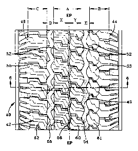
With reference to Figs. 4-6 and Fig. 8, a tire 40
having a tread 42 according to a preferred embodiment
of the present invention is shown. The tread 42 when
configured annularly has an axis of rotation R, first
and second lateral edges 44,46. The first lateral
edge 44 is toward the outside or outboard side of the
vehicle while the second lateral edge 46 is designed
to be mounted inboard or toward the inside of the
vehicle.
The tread 42 has a plurality of ground engaging
traction elements 52 separated by circumferential
grooves 54,55,56 and lateral grooves 58. Each
traction element includes one or more sipes 47, the
sipe or sipes extending laterally completely across
the element. The lateral grooves 58 may intersect and
join to form a continuous lateral groove path across
the entire tread width. Alternatively, the lateral
212~6~~
- 1~
grooves 58 may be laterally or circumferentially
spaced and never connecting, or may meet at a groove.
The traction elements 52 as shown are block elements;
however, the traction elements 52 could be ribs or a
combination of circumferentially continuous ribs and
block elements. The tread 42 as illustrated in Fig s
4-6 has an overall net contact area of about 62%
measured from tread lateral edge to tread lateral
edge. It is believed that the tire can be
successfully produced with treads having overall net
contact areas between 50% and 80%.
The tread 42 is divided laterally into three
tread zones, 60,61,62. The first zone 60 is
positioned between the two wide circumferential
grooves 54,55. The second zone 61 is located between
the first lateral edge 44 and the first wide groove
54. The third tread zone 62 is located between the
second lateral 46 edge and the second wide groove 55.
The outer or second tread zone 61 is intended to be
mounted on the outer or outboard side of the vehicle
(not shown) and the third tread zone 62 is intended to
be on the inboard side. The second tread zone 61
preferably has a net contact area higher than the
third tread zone 62 while the first tread zone 60
preferably has a net contact area between the value of
the second zone 61 and 90% of the value of the third
tread zone 62. Each zone is defined as the area
between specified boundary edges. The first zone 60
has boundary edges defined by two planes, one plane
passing through the intersections of the long bases 75
and the axially adjacent sides 73 of each groove 54
and 55. The second zone has boundary edges defined by
the lateral edge 44 and a plane passing through the
intersections of the long base 75 and the sides 74 of
the window 72 of groove 54 closest in proximity to the
- 11 - y1246~~
lateral edge 44. The third zone 62 has boundary edges
defined by the second lateral edge 46 and a plane
passing through the intersections of the long base 75
and the side 74 of the window 72 of the groove 55.
With particular reference to Fig. 5, it can be
seen that the first or central tread zone 60 has an
axial width A, the second tread zone 61 an axial width
B, and the third zone 62 an axial width C. In the
preferred embodiment, the axial width A is greater
than B or C, and axial width B is greater than C.
Also, groove 54 has a long base 75 having an axial
width E while groove 55 has a long base 75 having an
axial width D, E being greater than D. These subtle
features provide very specific and significant
improvements. The central zone 60 when used on the
lightly loaded rear wheel position of a light truck
bears most of the load. Zone 60 has the greatest
axial width which correspondingly means that the zone
60 may have a lower net-to-gross ratio than if each
tread zone had been equal in axial width. The central
zone 60 has a net-to-gross ratio of about 72% and an
axial width of about 33% of TW. The second tread zone
61 has a net-to-gross ratio of about 83% and an axial
width of about 23% of TW. The third tread zone 62 has
a net-to-gross ratio of 73% and an axial width of 21%
of TW. Groove 54 has an axial width of about 13% of
TW and groove 55 has an axial width of 10% of the
tread width TW. This change in axial widths from
tread zone to tread zone enables the pattern to remain
generally open over 77% of the tread width TW. The
wide groove 54 adjacent the second tread zone 61 is
about 30% wider than the opposite wide groove 55
adjacent the third zone 62. This feature permits the
second zone 61 to exhibit a much higher net-to-gross
ratio for improved wear and noise while increasing the
- 12
volume of water that can be accommodated by the wide
groove 54. The other groove 55 can be narrower due to
the more open and wider lateral grooves which
effectively balance the water handling capability of
the tire 40.
With reference to Fig. 6, the tread 42 has a
radial height h as measured from the base 43 to the
radially outer road contacting surface 53. The zig-
zag portion 70 of the grooves 54,55 have a radial
height ranging from 0% to 100% of h. Alternatively,
the zig-zag portion 70 may have a radial height
ranging from 25% to 100% of h. Groove 54 illustrates
a zig-zag groove portion 70 that has a radial height
starting at about 25% of h. Furthermore, the tread
having a maximum radial height h, as measured from the
tread base 43 to the road contacting surface 53, may
have a zig-zag portion 70 having a maximum radial
height in the range of 75% to 100% h, the height being
dependent on the amplitude of the zig-zag and the
width of the long base 75. Assuming the amplitude of
the zig-zag is less than the width of the long base
75, then the maximum radial height of the zig-zag will
be less than 100% h.
For the purposes of this invention, the
measurements taken from the tread base 43 disregard
tread wear indicators or stone penetration protection
protrusions that may extend from the tread base 43.
Additionally, the triangular or trapezoidal shaped
window extends similarly to the tread base 43, the
sides 73,74 of the window 72 define the maximum axial
extent the zig-zag can protrude into the groove 54,55.
If the zig-zag portion 70 has a minimum radial height
greater than 0% of h then the zig-zag portion will
intersect the triangular or trapezoidal side 73,74 at
13
the point of its minimum radial height. Groove 54
displays such a condition as described above.
As can be seen from the figures and description,
the prior art tread of the Wrangler GSA~ and the
preferred embodiment tread 42 of the present invention
have many common features. The tire 40 of the present
invention as shown in Figs. 4-6 has employed the use
of a unique wide groove design.
The wide groove 54,55 is uniquely designed to
improve the hydroplaning resistance and wet traction
capability of a light truck tire tread such as that
shown in Figs. 1-3, while at the same time maintaining
the off-road and snow traction capability of the tire.
The wide groove 54,55 has a first portion 70
extending radially from the tread base in a
circumferentially continuous zig-zag path. The wide
groove has a window portion 72 extending radially
inwardly from the outer surface 53 of axially adjacent
traction elements 52 to the tread base 43. The window
portion 72 radially superimposes the first zig-zag
portion 70 of the groove 54,55. As shown in Fig. 8,
the window portion 72 follows a circumferentially
continuous straight path. The window portion 72 has a
cross-sectional shape approximately or substantially
triangular or trapezoidal. The triangular or
trapezoidal shape has two sides 73,74, a radially
outer long base 75, and a radially inner short base 76
or point of intersection 76. The sides 73,74 of the
trapezoid defines the maximum axial extent of the zig-
zag portion 70 into the groove 54,55.
As illustrated in Fig. 5, the zig-zag portion 70
has an amplitude about equal to the axial width (E or
D) of the long base 75. It is believed that the
amplitude can vary from 50% to 150% of the axial width
- 14 -
of the long base 75. The long base 75 has an axial
width in the range of 7% to 20% of the tread width TW,
preferably about 7% to 10%.
As illustrated in Figs. 4-6 of the preferred
embodiment, two such wide grooves 54,55 are shown.
Groove 55 bounding the third tread zone 62 has a
window portion 72 wherein the sides 73,74 of the
trapezoid are linearly inclined radially and axially
outwardly from the groove center, the sides 73 and 74
of groove 55 being inclined at an angle 91 for side 74
and B2 for side 73 greater than 20° relative to the
radial direction preferably 32°. As shown, the
inclination of the sides 73,74 of groove 54 can be
different relative to the radial direction. The side
74 in closest proximity to the lateral edge 46 having
an inclination 94 greater than the inclination 93 of
the side 73 closest to the equatorial plane, side 73
being 5° and 74 being greater than 20°, preferably
about 34°.
Alternatively, the wide groove 54 as illustrated
has the two sides 73,74 of the trapezoidal shaped
window portion similarly inclined. The sides 73,74,
instead of extending entirely linearly, have a
radially outer convex curvature 78 at the radially
outermost extreme.
Although the preferred embodiment disclosed the
use of two wide grooves 54,55 as described above, for
light truck vehicles one such groove 54,55 may be
employed in a tread pattern. It is believed feasible
to employ such a groove 54,55 at the equatorial plane.
Alternatively, the wide groove could be asymmetrically
employed on just one side of a tread between the
lateral edge and the equatorial plane. The use of at
least one such wide groove is believed to improve the
wet handling characteristic without sacrificing snow
-15- 212468
or off-road traction performance as compared to
conventional tread patterns.
The aggressive zig-zag portion 70 of the groove
54,55 provides superb snow or mud traction providing
many traction surfaces for forward momentum. By
superimposing the window portion 72 over the zig-zag
portion 70, a circumferentially continuous
unobstructed trapezoidal shaped water channel is
formed. This straight window portion facilitates
water flow through the channel and increases the
amount of water volume occupied by the groove. As
shown in Fig. 7, conventional prior art zig-zag type
grooves 24,25 obstruct water flow and diminish the
amount of water volume that can be occupied by the
groove.
With reference to the present invention as shown
in Fig. 8, the lateral grooves are located to
facilitate water flow. By intersecting the groove
54,55 with lateral extending grooves 58, additional
water channeling can be achieved. The intersection of
the lateral grooves 58 are preferably located
circumferentially at or near the amplitude peaks of
the zig-zag first portion 70. This feature, when
combined with the wide grooves 54,55, can channel the
water simultaneously laterally as well as
circumferentially. The use of the lateral groove
reduces the water flow restriction created by the
protruding portions of the zig-zag portion 70.
Conventional zig-zag grooves 24,25, as shown in
the prior art tire of Fig. 7, have protruding portions
that axially overlap or almost axially overlap from
side to side. This creates a natural obstruction to
water flow and therefore the tire 10 effectively can
only absorb the water trapped in the voids of the
grooves. This can limit the depth of water at a given
- 16 -
speed that can be accommodated without experiencing a
loss of road contact of the tread 12, a phenomena
commonly called hydroplaning. Alternatively, the tire
can be limited at a given depth of water to a
5 certain speed prior to experiencing the loss of road
contact.
Experimental tests compared the prior art tire as
shown in Figs. 1-3 with a similarly constructed tire
according to Figs. 4-6 of the present invention. Each
10 tire 10,40, as illustrated in Figs. 3 and 6
respectively, had a carcass, a pair of annular beads
15,45, a pair of radial carcass plies 17,47 extending
from bead 15,45 to bead 15,45, and wrapped about each
bead 15,45, a belt reinforcement 19,49 radially above
the plies 17,47, and a pair of sidewalls 21,41, one
extending from each bead to the tread 12,42, the tread
12,42 being radially outward and adjacent the belt
reinforcement 19,49. Each tire tested, both the prior
art control tire 10 and the test tire 40, used the
same materials and components except for the tread
design configuration.
~l 2 9 6 ~~
- 17 -
TEST SUN~1ARY
Tire
According
to the
ontrol Present
Tire Invention
Treadwear 100 110
Wear Uniformity 100 110
Wet Traction 100 109
Hydroplaning 100 112
Dry Traction 100 97
Snow Traction 100 96
Mud Traction 100 95
Gravel Traction 100 89
Noise 100 108
Ride Harshness 100 100
Handling Dry 100 100
Weight 29.0 lbs 28.23 lbs
The wet traction tests were conducted at speeds
of 60 mph. The hydroplane studies were tested at .080
inches of water depth at speeds of 80 mph. The
control Wrangler GSA~ maintained 42.7% of its contact
path while the test tire retained 48.0%. Typically,
many tires can lose most, if not all, of their contact
path under such test conditions.
The treadwear data and the noise data were also
considered very promising due in part to the more open
appearance and the less tread rubber used. As can be
seen, the tread of the test tire weighed about three-
quarters of a pound less than the control tire.
21~46p8
-18-
Normally one would expect a decrease in treadwear and
a possibly noisier tread. The present invention
places the tread rubber in the regions of highest
load. By having the outboard shoulder zone in the
form of a closed rib, much of the generated tire noise
is trapped and muffled under the vehicle.
The differences between the control tire and the
test tire are more significant in view of the
similarities of the tread patterns as previously
discussed. The improved performance results are
believed to be directly attributable to unique tread
pattern, the employment of the wide grooves 54,55, and
the combination of these grooves and the lateral
groove's placement.
The control tire as described is known for
exceptional traction and wear performance. The
Wrangler GSA~ is commonly used in off-road racing;
therefore, the slight drop in snow and mud traction
was perceived as very encouraging. The improvements
achieved are, therefore, believed to be quite
outstanding in view of the control tire's already
excellent attributes.
The above test results were based on molded
control and test tires utilizing the same carcass.
Additional on-going treadwear and ancillary testing of
molded tires was still- in progress at the time of this
writing.