Sélection de la langue

Search

Sommaire du brevet 2124918 

Énoncé de désistement de responsabilité concernant l'information provenant de tiers

Une partie des informations de ce site Web a été fournie par des sources externes. Le gouvernement du Canada n'assume aucune responsabilité concernant la précision, l'actualité ou la fiabilité des informations fournies par les sources externes. Les utilisateurs qui désirent employer cette information devraient consulter directement la source des informations. Le contenu fourni par les sources externes n'est pas assujetti aux exigences sur les langues officielles, la protection des renseignements personnels et l'accessibilité.

Disponibilité de l'Abrégé et des Revendications

L'apparition de différences dans le texte et l'image des Revendications et de l'Abrégé dépend du moment auquel le document est publié. Les textes des Revendications et de l'Abrégé sont affichés :

  • lorsque la demande peut être examinée par le public;
  • lorsque le brevet est émis (délivrance).
(12) Brevet: (11) CA 2124918
(54) Titre français: AGRAFE POUR BANDE TRANSPORTEUSE
(54) Titre anglais: FASTENER FOR CONVEYOR BELTS
Statut: Durée expirée - au-delà du délai suivant l'octroi
Données bibliographiques
(51) Classification internationale des brevets (CIB):
  • F16G 03/07 (2006.01)
  • F16G 03/04 (2006.01)
(72) Inventeurs :
  • HEROLD, WOLFGANG (Allemagne)
(73) Titulaires :
  • MATO MASCHINEN- UND METALLWARENFABRIK CURT MATTHAEI GMBH & CO. KG
(71) Demandeurs :
  • MATO MASCHINEN- UND METALLWARENFABRIK CURT MATTHAEI GMBH & CO. KG (Allemagne)
(74) Agent: MACRAE & CO.
(74) Co-agent:
(45) Délivré: 2005-01-04
(22) Date de dépôt: 1994-06-01
(41) Mise à la disponibilité du public: 1994-12-08
Requête d'examen: 2001-04-30
Licence disponible: S.O.
Cédé au domaine public: S.O.
(25) Langue des documents déposés: Anglais

Traité de coopération en matière de brevets (PCT): Non

(30) Données de priorité de la demande:
Numéro de la demande Pays / territoire Date
P 43 18 836.2 (Allemagne) 1993-06-07

Abrégés

Abrégé français

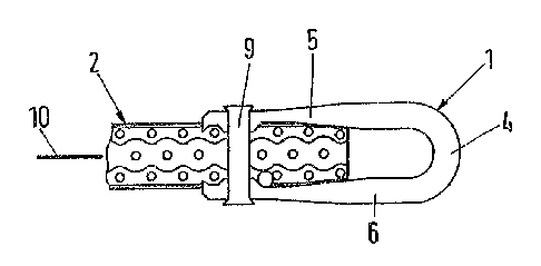
La présente invention concerne une agrafe pour bande transporteuse (2), en particulier une agrafe ayant un élément de corps (3) avec une section transversale en forme de U, contenant au moins un parmi un illet de couplage presque semi-circulaire (4) et une patte de fermeture (5, 6) avec une fente d'entrée (7, 8) pour au moins une épingle de fermeture (9). L'essence de l'invention repose sur le fait que l'épingle de fermeture est en forme de tige et comporte deux extrémités arrondies (14, 14').


Abrégé anglais

The invention concern a fastener for conveyor belts (2), specifically one with a body element (3) with a U shaped cross section, containing at least one almost semicircular coupling eyelet (4) and a fastening leg (5, 6) with entrance slot (7, 8) for at least one fastening pin (9). The essence of the invention lies in the fact that the fastening pin is peg shaped and displays two blunt ends (14, 14').

Revendications

Note : Les revendications sont présentées dans la langue officielle dans laquelle elles ont été soumises.


7
THE EMBODIMENTS OF THE INVENTION IN WHICH AN EXCLUSIVE PROPERTY OR
PRIVILEGE IS CLAIMED ARE DEFINED AS FOLLOWS
1. A fastener for conveyor belts and the like, comprising:
a body element having a generally U-shaped side configuration which defines a
coupling
eyelet for receiving a connecting pin therein; said body element including a
pair of legs shaped
for positioning on opposite sides of an associated belt end, wherein each of
said legs has a
fastener aperture therethrough positioned such that the fastener apertures on
said legs are
mutually aligned when said body element is clenched on the belt end; and
a rigid fastening pin having a cylindrical sidewalk with one end portion
thereof closely
received and frictionally retained in the fastener aperture of one of said
legs to interconnect the
same in a selected pre-clenched condition; said fastening pin having a blunt
end associated with
said one end portion which, when said body element is clenched on the belt
end, is driven
through an adjacent previously unapertured portion of the belt end, and
closely received in the
fastener aperture of the other one of said legs, and subsequently upset to
positively interconnect
the same.
2. A fastener as set forth in claim 1, wherein:
said fastening pin blunt end has a flat planar face oriented generally
perpendicular to said
sidewall.
3. A fastener as set forth in claim 2, wherein:
said fastener aperture on said other leg has an inwardly tapered outer end to
receive an
upset end of said fastening pin therein.
4. A fastener as set forth in claim 3, wherein:
said other leg includes a ring-shaped boss positioned concentric with said
fastener
aperture thereon, and protruding inwardly thereof.
5. A fastener as set forth in claim 4, wherein:

8
said coupling eyelet has a first predetermined material strength in a radial
direction; and
said fastening legs each have a second predetermined material strength
adjacent said
fastener aperture, which has a measure that is substantially one-half of that
of said first material
strength.
6. A fastener as set forth in claim 5, wherein:
said legs each have a wedge shaped side elevational configuration.
7. A fastener as set forth in claim 6, wherein:
said fastening pin has a predetermined length that is accurately cut to an
associated gauge
block.
8. A fastener as set forth in claim 7, wherein:
said fastening pin is constructed from a high tensile material.
9. A fastener as set forth in claim 8, wherein:
said fastening pin includes a head at an end thereof opposite said blunt end.
10. A fastener as set forth in claim 9, wherein:
said fastening pin includes a second end opposite said blunt end which is also
blunt.
11. A fastener as set forth in claim 10, wherein:
said blunt second end of said fastening pin has a flat planar face oriented
generally
perpendicular to said sidewall.
12. A fastener as set forth in claim 1, wherein:
said fastener aperture of said other leg has an inwardly tapered outer end to
receive an
upset end of said fastening pin therein.
13. A fastener as set forth in claim 1, wherein:
said other leg includes a ring-shaped boss positioned concentric with said
fastener

9
aperture thereon, and protruding inwardly thereof.
14. A fastener as set forth in claim 1, wherein:
said coupling eyelet has a first predetermined material strength in a radial
direction; and
said fastening legs each have a second predetermined material strength
adjacent said
fastener aperture, which has a measure that is substantially one-half of that
of said first material
strength.
15. A fastener as set forth in claim 1, wherein:
said legs each have a wedge shaped side elevational configuration.
16. A fastener as set forth in claim 1, wherein:
said fastening pin has a predetermined length that is accurately cut to an
associated gauge
block.
17. A fastener as set forth in claim 1, wherein:
said fastening pin is constructed from a high tensile material.
18. A fastener as set forth in claim 1, wherein:
said fastening pin includes a head at an end thereof opposite said blunt end.
19. A fastener as set forth in claim 1, wherein:
said fastening pin includes a second end opposite said blunt end which is also
blunt.
20. A fastener as set forth in claim 19, wherein:
said blunt second end of said fastening pin has a flat planar face oriented
generally
perpendicular to said sidewall.

Description

Note : Les descriptions sont présentées dans la langue officielle dans laquelle elles ont été soumises.


CA 02124918 2003-12-11
FASTENER FOR CONVEYOR BELTS
BACKGROUND OF THE INVENTION
The present invention concerns a fastening element for conveyor belts and the
like, and
in particular, to a fastener with a body element, U-shaped in cross section,
containing at least one
generally semicircular coupling eyelet and fastening legs with an entry
opening for at least one
fastening pin.
U-shaped belt fasteners are generally well known in the art. They are
connected to each
other with a coupling bar that reaches across the comb-like coupling eyelets.
Such fasteners
encompass each end of the conveyor belt with their U-shaped body element, and
in this position
are fastened to the conveyor belt ends with staples or rivets. Staples
typically extend relatively
far beyond the main body of the fastener after they are attached, and the same
is also true for rivet
heads when using rivets.
Furthermore, when rivets are used for fastening the connecting elements at the
ends of
conveyor belts, it is common practice to use relatively long pointed rivets,
which are shortened
to the required length after passing through the belt end and the associated
fastening legs.
Consequently, all rivets have to be cut off by hand after installation. This
is both labor intensive
and time consuming, and therefore expensive.
SUMMARY OF THE INVENTION
One objective of the present invention is to create a special fastener with a
matching
unique fastening pin, which makes the attachment of the fasteners to the belt
ends less
complicated and less expensive.
The present invention solves this problem by designing a fastening pin that is
peg shaped
and has two blunt ends. One of the two ends of the peg-shaped fastening pin
may have a rivet
head. The other end is to remain preferably flat and, according to the
invention, is pressed
directly through the belt end. On the other side of the belt, the fastening
pin enters the applicable

CA 02124918 2003-12-11
2
opening in the fastening leg, and there is immediately peened or pressed into
place. For instance,
this can occur with a punch that slightly expands the blunt end of the
fastening pin, so that the
end is anchored tightly and securely in the opening or the entrance slot of
the fastening legs.
In summary, therefore, the present invention may be considered as providing a
fastener
for conveyor belts and the like, comprising: a body element having a generally
U-shaped side
configuration which defines a coupling eyelet for receiving a connecting pin
therein; the body
element including a pair of legs shaped for positioning on opposite sides of
an associated belt
end, wherein each of the legs has a fastener aperture therethrough positioned
such that the
fastener apertures on the legs are mutually aligned when the body element is
clenched on the belt
end; and a rigid fastening pin having a cylindrical sidewalk with one end
portion thereof closely
received and frictionally retained in the fastener aperture of one of the legs
to interconnect the
same in a selected pre-clenched condition; the fastening pin having a blunt
end associated with
the one end portion which, when the body element is clenched on the belt end,
is driven through
an adjacent previously unapertured portion of the belt end, and closely
received in the fastener
aperture of the other one of the legs, and subsequently upset to positively
interconnect the same.
Further characteristics of the invention will be further understood and
appreciated by
reference to the following claims in connection with the description and the
drawings.
The present invention is described below in more detail with respect to a
production
sample, as illustrated in the drawings.
BRIEF DESCRIPTION OF THE DRAWINGS
Fig. 1: A longitudinal section of a fastener before use;
Fig. 2: A cross section along the line II--II in Fig. 3;

212918
Fig. 3: A top view of a conveyor belt with several fasteners;
Fig. 4: An enlarged section or side view of the end of a conveyor belt with a
fastener
before it is fastened;
Fig. 5: A crass section view like that of fig. 4, together with the tool
components, before
the penetration of the peg shaped fastening pin through the conveyor belt. .
F'ig. 6: A cross section view like that~offig. 5, immediately before the ends
afth~
fastening pins are pressfitted;
Fig. 7: A cross section or side view like those in fig. 4 - 6 of the conveyor
belt end
with an attached fastener
A fastener ~1 for canveyar.belts 2 consists of a body element 3, which
contains at least one
and, preferably as In this example, two semicircular coupling eyelets 4 and
two fastener
legs 5 and 6 with openings or entrance slots 7, & for the fastening pin ~.
The coupling eyelets 4 display a fnll crass section. The material strength S1
of the
coupling eyelets a in xadial direction - at Ieast across the largest part of
its circumference -
is at Ieast twice as large as the material strength S2 of the fastener legs 5,
6 in the area of
their entrance slots 7, &. The fig. 1 and 2 show this clearly.
because o~the difFerences in material strength in the area of the coupling
eyelets 4 and the
fastening Iegs 5, b, the cross section of the fastening legs 5, 6,
perpendicular to the
conveyor belt surface, 10 is wedge shaped . To achieve a gradual transition
from the

~~~~l~l
fasaening legs 5, 6, to the coupling eyelets 4, the cross section of the
fastening legs 5, 6
diverges from the entrance slots 7, 8 to the coupling eyelets 4.
As shown in the diagrams, two coupling eyelets 4 each form, together with
their
applicable fastening legs S, Via, a fastener 1 in one piece construction.
Corresponding to the
gap 11 between the coupling eyelets 4, preferably bath fastening legs 5, 6
display
gradually diminishing indentation 12 (Fig. 3) within the continuation of the
gap 11.
Ring shaped bosses 13 surround each entrance slot ?, 8 on the side facing the
conveyor
belt and each entrance slot 7, 8 also displays on the outside of the fastening
legs 5', 6' or 5,
6 a tapered or conical indentarian 7a or 8a, as shown clearly in Fig. 4.
The fasting pins 9; used for attaching the fasteners 1 to the ~anweyor belt 2,
are peg-
shaped, of a defined gauge block (L), and possess two blurt ends 14 or I4', as
shown in
the production sannple illustrated in the diagrams above. Tt is also possible
to place a rivet
head 14" on the other end 14'. Nevertheless, it is advantageous for both sides
14, 1~' to
have flat faces 15, as shown in ixgures 1 and ~.
The attachment of the fastener 1 to the end 16 of the conveyor belt 2 proceeds
with an
upper tool 17 and a lower tool 18 as shown in figures 5 and 6. In this
operation, the
upper tool 17 presses the fastening leg 5 to the belt end 15, until the
entrance slot 7 in the
fastening leg 5 aligns with the peg shaped fastening pin 9, which is
positioned in the
entrance slot 8 of the other fastening leg 6. Then a punch 19 in the lower
tool 18 forces
the peg shaped fastening pin 9 through the conveyor belt z, until its leading
end 14 is
located in the entrance slot 8 of the other fastening leg 6. The upper tool
also has a punch
20, which is aligned with the punch 19 of the lower tool 18. loth rams can be
moved
independently from one another, as is indicated by the arrows in fig,. 5.

~~~4~1~
As soon as the fastening pin 9 has penetrated the conveyor beh 2 in the
prescribed
manner, the two rams 19, 20 exert force on the blunt ends 14 and 14' of the
fastening pin
9 and anchor or pressfit the ends 14 and 14' in the entrance slots 7 and 8.
Consequently,
the ends 14 and 14' also fill the conical indentations ?a or 8a of the
entrance slats 7 and 8.
~f the punch ends 19 and 20 containt paints 20 or 21 (Fig. 6), then
corresponding
impressions will form on the faces 15 of the fastening pins 9.
Depending on the length ofthe fastening pin 9, it either does not project at
all from the
outer contour of the fastener 1 aver the ends 14 and 14' are pressfltted, as
is shown in &g.
2, or the ends 14, 14' protrude slightly as indicated In fig. ?. A possible
projection should,
not e~cceed the raaximurn of 0.2 mm.
According to the production sample, the fastening pin 9 does not display a
raised civet
head, neither at its original condition nor after the attachraent is
completed.
Furth~rmore, it is essential to note, that no taper or spik~ is included in
the design for
easing the penetration of the fastening pin 9 into the conveyor belt 2.
Finally it is advantageous, if both ends ofthe peg shaped fastening pin 9 are
blunt, because
that facilitates the ease of production and assembly, especially, since the
penetration
through the conveyor belt already proceeds with the aid ofthe point 21 of the
pwch 19, ,
used for expanding the fastening pin ends.
As is common practice, several fasteners 1 are joined together into an
installation unit with
a wire 23 (Fig. 1) ar the like for improved utility, as seen In fig. 3.

The invention is not limited to the production sample illustrated in the
diagrams, moreover
alterations and modifications are possible without deviating from the essence
of the
invention. For instance, fastening pens 9 with blunt ends 14, 14' can also be
used for
attaching plate shaped fasteners to conveyor belts, and basically there are
further aheration
possible in the form and the design of the fasteners) 1 and the tools. The
essential fact is,
that the fastening pin 9 has blunt ends 14, 14', that it is forced with its
blunt end '14
through the belt end 16, and that the blunt ends 14, 14' are so pressfitted
into the entrance
slots 7 ar 8, as to be securely anchored in place. The diameter ofth~a
entrance slat 7, into
rwhich the end 14 of the fastening pin 9 is inserted, is about 0.1 mm larger
than the
diameter of the other entrance slot $. only a slight increase of the outer
diameter occurs
during the easpanding or press~tting of the pin ends 14 or 14':
After all, the peg shaped fastening pin consists of high tensile material.

Dessin représentatif
Une figure unique qui représente un dessin illustrant l'invention.
États administratifs

2024-08-01 : Dans le cadre de la transition vers les Brevets de nouvelle génération (BNG), la base de données sur les brevets canadiens (BDBC) contient désormais un Historique d'événement plus détaillé, qui reproduit le Journal des événements de notre nouvelle solution interne.

Veuillez noter que les événements débutant par « Inactive : » se réfèrent à des événements qui ne sont plus utilisés dans notre nouvelle solution interne.

Pour une meilleure compréhension de l'état de la demande ou brevet qui figure sur cette page, la rubrique Mise en garde , et les descriptions de Brevet , Historique d'événement , Taxes périodiques et Historique des paiements devraient être consultées.

Historique d'événement

Description Date
Inactive : Périmé (brevet - nouvelle loi) 2014-06-01
Inactive : CIB de MCD 2006-03-11
Accordé par délivrance 2005-01-04
Inactive : Page couverture publiée 2005-01-03
Inactive : Taxe finale reçue 2004-10-22
Préoctroi 2004-10-22
Un avis d'acceptation est envoyé 2004-04-27
Lettre envoyée 2004-04-27
Un avis d'acceptation est envoyé 2004-04-27
Inactive : Approuvée aux fins d'acceptation (AFA) 2004-03-18
Modification reçue - modification volontaire 2003-12-11
Inactive : Dem. de l'examinateur par.30(2) Règles 2003-09-26
Modification reçue - modification volontaire 2001-08-22
Inactive : Dem. traitée sur TS dès date d'ent. journal 2001-06-20
Lettre envoyée 2001-06-20
Inactive : Renseign. sur l'état - Complets dès date d'ent. journ. 2001-06-20
Toutes les exigences pour l'examen - jugée conforme 2001-04-30
Exigences pour une requête d'examen - jugée conforme 2001-04-30
Demande publiée (accessible au public) 1994-12-08

Historique d'abandonnement

Il n'y a pas d'historique d'abandonnement

Taxes périodiques

Le dernier paiement a été reçu le 2004-05-10

Avis : Si le paiement en totalité n'a pas été reçu au plus tard à la date indiquée, une taxe supplémentaire peut être imposée, soit une des taxes suivantes :

  • taxe de rétablissement ;
  • taxe pour paiement en souffrance ; ou
  • taxe additionnelle pour le renversement d'une péremption réputée.

Les taxes sur les brevets sont ajustées au 1er janvier de chaque année. Les montants ci-dessus sont les montants actuels s'ils sont reçus au plus tard le 31 décembre de l'année en cours.
Veuillez vous référer à la page web des taxes sur les brevets de l'OPIC pour voir tous les montants actuels des taxes.

Historique des taxes

Type de taxes Anniversaire Échéance Date payée
TM (demande, 3e anniv.) - générale 03 1997-06-02 1997-06-02
TM (demande, 4e anniv.) - générale 04 1998-06-01 1998-05-06
TM (demande, 5e anniv.) - générale 05 1999-06-01 1999-05-10
TM (demande, 6e anniv.) - générale 06 2000-06-01 2000-04-27
TM (demande, 7e anniv.) - générale 07 2001-06-01 2001-04-26
Requête d'examen - générale 2001-04-30
TM (demande, 8e anniv.) - générale 08 2002-06-03 2002-05-01
TM (demande, 9e anniv.) - générale 09 2003-06-02 2003-05-09
TM (demande, 10e anniv.) - générale 10 2004-06-01 2004-05-10
Taxe finale - générale 2004-10-22
TM (brevet, 11e anniv.) - générale 2005-06-01 2005-05-13
TM (brevet, 12e anniv.) - générale 2006-06-01 2006-05-24
TM (brevet, 13e anniv.) - générale 2007-06-01 2007-05-28
TM (brevet, 14e anniv.) - générale 2008-06-02 2008-05-23
TM (brevet, 15e anniv.) - générale 2009-06-01 2009-05-22
TM (brevet, 16e anniv.) - générale 2010-06-01 2010-05-20
TM (brevet, 17e anniv.) - générale 2011-06-01 2011-05-19
TM (brevet, 18e anniv.) - générale 2012-06-01 2012-05-16
TM (brevet, 19e anniv.) - générale 2013-06-03 2013-05-27
Titulaires au dossier

Les titulaires actuels et antérieures au dossier sont affichés en ordre alphabétique.

Titulaires actuels au dossier
MATO MASCHINEN- UND METALLWARENFABRIK CURT MATTHAEI GMBH & CO. KG
Titulaires antérieures au dossier
WOLFGANG HEROLD
Les propriétaires antérieurs qui ne figurent pas dans la liste des « Propriétaires au dossier » apparaîtront dans d'autres documents au dossier.
Documents

Pour visionner les fichiers sélectionnés, entrer le code reCAPTCHA :


Pour visualiser une image, cliquer sur un lien dans la colonne description du document (Temporairement non-disponible). Pour télécharger l'image (les images), cliquer l'une ou plusieurs cases à cocher dans la première colonne et ensuite cliquer sur le bouton "Télécharger sélection en format PDF (archive Zip)" ou le bouton "Télécharger sélection (en un fichier PDF fusionné)".

Liste des documents de brevet publiés et non publiés sur la BDBC .

Si vous avez des difficultés à accéder au contenu, veuillez communiquer avec le Centre de services à la clientèle au 1-866-997-1936, ou envoyer un courriel au Centre de service à la clientèle de l'OPIC.

({010=Tous les documents, 020=Au moment du dépôt, 030=Au moment de la mise à la disponibilité du public, 040=À la délivrance, 050=Examen, 060=Correspondance reçue, 070=Divers, 080=Correspondance envoyée, 090=Paiement})


Description du
Document 
Date
(aaaa-mm-jj) 
Nombre de pages   Taille de l'image (Ko) 
Dessin représentatif 1999-07-12 1 5
Revendications 1995-04-07 2 92
Description 1995-04-07 6 298
Revendications 2003-12-10 3 98
Dessin représentatif 2004-04-04 1 7
Abrégé 1995-04-07 1 10
Dessins 1995-04-07 3 46
Description 2003-12-10 6 213
Rappel - requête d'examen 2001-02-04 1 118
Accusé de réception de la requête d'examen 2001-06-19 1 179
Avis du commissaire - Demande jugée acceptable 2004-04-26 1 161
Correspondance 2004-10-21 1 32
Paiement de taxe périodique 1996-05-15 1 44