Note : Les descriptions sont présentées dans la langue officielle dans laquelle elles ont été soumises.
D-20013
.-.
21255:1
- 1 -
LOW HEAT-L~Ax _ CfIT.iFRFNT-~~onn_~r CRYOGElv1'I~' SYSTFw~r
BACKGROUND
This invention relates to a low heat-leak system
' for containing or guiding fluids at cryogenic
temperatures.
In the containment or guidance of fluids at
cryogenic temperatures, namely, cryogenic fluids, it is
important to provide a system that will have a very low
rate of heat transmission, that is, heat leak from the
surface exposed to ambient atmosphere to the surface
exposed to the fluid at cryogenic temperature. Because
of the large temperature difference, the thermal
driving potential is very high. Heat. leak into a fluid
at cryogenic temperature is particularly costly and
undesirable because of the large amount of work
required in achieving the cryogenic temperature,
particularly, in liquefying a gas to form a fluid at
cryogenic temperature:
The cryogenic temperature range has been
identified in publications, and as is used herein
extends from OK to about 172K. Insulative systems that
perform satisfactorily at temperatures above cryogenic
temperatures usually do not perform satisfactorily at
cryogenic temperatures. At temperatures below the
freezing temperature of water, insulative systems have
low internal vapor pressure, which creates high
potential for atmospheric moisture to enter the system
and impair the insulative quality of a system.
In systems for containing or guiding fluids at
cryogenic temperatures, heat leak is usually decreased
by providing a space of reduced gaseous pressure, that
is, a space evacuated of air or gas to some degree to
reduce heat transmission by gaseous conduction. The
structure necessary varies with the subatmospheric
pressure in the space or degree of evacuation. Higher
D-20013
- 2 -
degrees of evacuation require stronger and thicker
walls and structures to support the pressure
differential between the evacuated space and the
ambient atmosphere.
To reduce heat transmission by radiation, the
space usually is filled at least in part with radiation
shields, a powder or a matrix of solids and voids. A
high degree of evacuation is still typically necessary
to achieve tolerable rates of heat transmission across
the space. The matrix or powder usually contributes
somewhat to the heat transmission rate across the space
by conduction through the solid portion of the matrix
or powder.
What is needed is a system for containing or
guiding fluids at cryogenic temperatures wherein low
heat leak is attained without a high degree of
evacuation and without a high strength structure. This
invention satisfies these needs. The invention employs
a coherent aerogel to achieve low rates of heat
transmission, preferably with gaseous environment
pressures higher than used with other materials in the
prior art. The coherent aerogel is in a fixed form
capable of bearing and transmitting load so that the
structure surrounding the aerogel preferably need not
support fully the pressure loading imposed by the
ambient atmosphere, but can transmit the pressure
loading from one external face of the enclosure,
through the aerogel, to the other face of the
enclosure, thereby balancing the pressure loading of
. the ambient atmosphere.
Aerogels are water-free gels dried in such a way
that the solid matter in the gel remains intact. The
~resultfng solid is an amorphous lattice structure with
,ultrafine open cells typically consisting of 1 to 5%
solid matter. Aerogels.have continuous porosity and a
D-20013
CA 02125519 1998-09-22
- 3 -
microstructure of interconnected colloidal-like
particles or polymeric chains with characteristic
diameters of 0.01 micrometers. Abundant pores of
nanometer size through out the aerogel comprise most of
the aerogel's volume.
Inorganic aerogels which have been prepared in
coherent form include silica, alumina, zirconia,
tungsten, and titanium aerogels, made via the
hydrolysis and condensation of the metal alkoxide, for
example, tetramethoxy silane, in an alcohol to form an
alcogel. The alcogel is dried at supercritical
conditions for the alcohol, or at supercritical
conditions for a solvent substituted for the alcohol,
so as to form a coherent matrix, that is, a coherent
aerogel. Alternatively, the alcohol may be replaced
with a solvent which is extracted at supercritical
conditions for the solvent. Coherent aerogel based on
carbon has also been prepared.
Organic aerogels include resorcinol-formaldehyde
aerogels formed by the sol-gel polymerization of
resorcinol with formaldehyde under alkaline conditions.
A typical process is described in U.S. Patent No.
4,402,927 issued Sep. 6, 1983 to G. von Dardel.
Another organic aerogel is produced by the sole-gel
polymerization of melamine with formaldehyde,
introducing a PH change, and following with
supercritical extraction, as described in U.S.
Patent No. 5,086,085 issued Feb. 5, 1992 to R. W.
Pekala. Representative densities are from about
100 to about 800 kilograms per cubic meter.
All of the aerogels mentioned are capable of being
produced in a coherent form, are capable of compressive
load bearing, have low densities and display low
transmission of heat at atmospheric pressure, and at
D-20013
212~i~19
- 4 -
subatmospheric pressures, notably at low vacuum.
SUMMARY
This invention provides a low heat-leak cryogenic
system comprising:
(a) a cryogenic fluid;
(bj a first lamina having an external side
facing, and exposed directly to, or indirectly to, the
cryogenic fluid, and an internal side facing away from
the cryogenic fluid;
'(c) a second lamina spaced apart from the
internal side of the first lamina, the second lamina
having an internal side facing toward the first lamina
and an external side facing away from the first lamina;
and
(d) at least one layer of coherent aerogel
extending from the internal side of the first lamina to
the internal side of the second lamina.
In another version, the invention further
comprises about the coherent aerogel a gaseous
environment having a pressure of from about 200D to
about 100,000 micrometers of mercury.
In still another version of the invention, at
least one of the lamina are flexible so as to at least
partially transmit an external load, such as that
imposed by the atmosphere, to the coherent aerogel, and
the coherent aerogel is capable of at least partially
transmitting a load imposed on it from one lamina to
the other.
DRAWINGS
Fig. 1 is a sectional drawing of a cryogenic fluid
container to which the present invention has been
applied.
Fig. 2 is cross-sectional view at line 2-2 of the
~.f r ~.,";; .. . ....~... , , .~ ~ '~.'. ~.., ;. . ..: .. '. ". ,: ~-.v '. "
D-2 0 O 13
212 ~'~:1.J
- 5 -
container of Fig. 1 pursuant to one version of the
invention.
Fig. 3 is a cross-sectional view at line 2-2 of
the container of Fig. 1 pursuant to another version of
the invention.
Fig. 4 is a cross-sectional view at line 2-2 of
the container of Fig. 1 pursuant to another version of
the invention.
Fig. 5 is a graph of apparent thermal conductivity
of several materials in an environment of air at
various pressures between two surfaces respectively at
temperatures of 295K and 77K. Curve A is for coherent
silica aerogel as measured on two contiguous layers,
each 1.27 cm thick and having a density of 96 kilograms
per cubic meter. Curve B is for coherent silica
aerogel as measured on two similar contiguous layers
with a reflective aluminum foil on each of the two
outside surfaces of the two layers and a reflective
foil between the two layers. Curve C is for perlite
powder at a bulk density of 88 kilograms per cubic
meter. Curve D is for fiberglass with a bulk density
of 16 kilograms per cubic meter, manufactured by
Owens-Corning and designated as PF-210. Curve E is for
air calculated including convective effects between two
surfaces 2.54 cm apart, each with an emissivity of
0.074.
DESCRIPTION
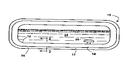
The invention will be described as applied to a
storage container for cryogenic fluid as depicted in
Fig. 1. The invention can be similarly applied to
other vessels, confinements or conduits for cryogenic
fluids. The storage container 10 has a first lamina 12 -
having an external side facing toward, and an internal
side facing away from, the cryogenic fluid 14. Usually
D-20013
~~2JJ~~
- 6 -
the first lamina 12 is exposed directly to the
cryogenic fluid, that is, in contact with the fluid and
serving to contain the fluid. Typically the first
lamina is comprised of metal sheet, is impervious to
the cryogenic fluid, and is capable of withstanding the
loads imposed by the fluid. Alternatively the first
lamina may be exposed indirectly to the fluid, that is,
the external side of the first lamina may be in contact
with another surface (not shown) which itself is in
direct contact with the cryogenic fluid and serves to
contain the fluid. When the container contains fluid
at cryogenic temperature, the first lamina approaches
the temperature of the cryogenic fluid.
Spaced from the internal side of the first lamina
12 is a second lamina 16 having an internal side facing
the internal side of the first lamina 12 and an
external side facing away from the first lamina 12.
Typically the external side of the second lamina 16 is
directly exposed to the ambient atmosphere. Optionally
a protective coating 17 may be provided on the external
Bide of the second lamina to guard against physical
damage and optionally to also retard the heat leak
rate. Suitable materials include organic foams such
as, for example, polystyrene or polyurethene foam.
Extending from the internal side of the first lamina 12
to the internal side of the second lamina 16, that is,
occupying the space therebetween, is at least one block
or layer of coherent aerogel. Multiple layers, blocks, .
bricks, mating pieces, or random pieces may be
employed. The first lamina and the second lamina can
be made to serve the multiple purposes of encapsulating
the coherent aerogel to provide a closed chamber which
may be evacuated of air or other gas and to protect the
coherent aerogel during handling. While the invention
is applicable to aerogels in general, silica aerogel is
D-20013
212~~1~
preferred because its base, silicon dioxide, has a
tetrahedral structure conducive to forming strong
molecular bonds and is nonflammable.
Coherent silica aerogel has a density of from
about 2o to about 160 kilograms per cubic meter,
preferably from about 60 to about i00 kilograms per
cubic meter for use fn the system provided by this
invention. The average pore size ranges from about
from about 0.01 to about 0.4 micrometers, preferably
from about 0.02 to about 0.1 micrometers. Larger pore
size typically corresponds with lower density. Pore
size as used herein means the average distance between
walls in the voids in the coherent material.
Coherent aerogel may be used in layers of
different pore size and density in a single
low-heat-leak system for a cryogenic installation.
When the system is in cryogenic service, the mean free
path of gas molecules comprising the gaseous
environment within the system proximate the colder
surface of the system is longer than that of gas
molecules proximate the warmer surface of the system.
,Hence, similar or even lower apparent thermal
conductivity may be obtained across coherent serogel
with a larger pore size proximate a colder surface in a
system than that which maybe obtained in coherent
aerogel with a smaller pore size proximate a warmer
surface in the system. To reduce the weight of aerogel
material used in a given application, as depicted in
Fig. 2, it is advantageous to use a lower density and
larger pore size in a layer 20 or layers adjacent to
the first lamina 12 where temperatures are colder, and
to use a higher density and smaller pore size in a
layer 22 or layers adjacent to the second lamina 16
where temperatures are warmer. System weight and cost
may thus be reduced while maintaining low heat leak
r :__.-, :':w: ...:-. , ~..... ,~: :: . ' ;...,.:. ........". _.,;.,..
.: ". h '-'... '. ':~'. ' , :' ... ..,. ... ...,.... .. ... ; . . .. .
'. ~ :'s'. ~ :n.::;~ :.:.r,.:" .. . -.:, . : ...., . .....
.... :.'. : , .-.e'.:.. ~ .:. -'..,..., . , . ~:;: ~ . ~ .'.
. . ,.,'~. '. t .... ...:: ~ . ..~. .
'' '~ W ,... :'. . '. .. . ...
' w .:..y.. '
:. : . "
:;. . ::
'
. :. : , n ;
~ .. .:. .
:. ..:: , : ~ : . ..
.:' . . "~ ~~ . ~ .,...":~.., :
.. ,'. , ';.:' Y .;.: 2~: . :.. .',.,', ,~:.;: '.:.: ..
.,,.: .. :, r .
7: . ' ~,~~
7...4..., ~ ~ f.:~' ' :,
n t ~
: ~
p .
: : .. . .:... '
.. .: .,
i . . ; ~ n':: . S.y.
. :;:. .:... ~.tr.. . . . ' .:. :.:: ; .:,'.,..
' ... . : .l:.s,... ; ;:.!.:. :,. - .: '.. .... .
'.':.~:v..:.~
.. ' . ..,.... ,s~ .'.. '
5..... i .,4 .1, t;.. f '. .;.,. .:.
. ,,:::.. :-..~ ,..':W r :':..':.
. .., . : : ~ ::,-,'.
4
.
7. . >t '.
t.: ,
y.... ; .. .,6.-.
.fY i .
v~
9 . 1 ,i r~ , .w
5
n .r r,
7.. r~
a '
~ ~ ~
x ~
. ,u~~~,y~,
a r
~,
x :J' '"4.. Y
..k ~ L ,,
r.... . 7" ~i~.
:, .,. ,F ' .. t. t
' . :
. ~;i..; .~yn...:.. ..: , .....s . >. ;'~s
,. ~. s r.
,: .,... . ., .
.... . .
, ;lu
~ ..
'
.
. . ~ ,
. .. . .
.. . . .
. .. .,
. ,
.
,
.. .:.. . .. ~ .. ..;
.~...: ~ ' .. .. :::: .,
~fi: '' -. . ~
~ : .
'.: : '..:
' .
:'
, . , , .
. .... :. _
. .. . .
, . . ~. . ., : . . .
; :: ~.. , ....:~.. ..
l~ .....,.... . ....::.. :...s.:. : . , '..,.:~... ' : .
,~..' 47:.,..~- ....., .. ,~ : :. ~ ~: ..-:. ~ .' :....~
.,.,.' Y . . ....... .~
. . .:':: ....:."..~.. ...:
:.,,y - ;' ' ... ...".,.
s:; ....n, - ,... .
,:~ i:' ::.." ' .,:~:"
,... '::~;., ' '
t ::
' " :
'~
. , ... .
, , . .
. .. . .
. . . ..
. ... . .: :n-.". . .
. . ~ ~....~.: , ~.:...': :: :.: :..:
n ... "..::: ::': . ..: ~.~ .. . , ._:..
._ ._... .:,. .:., .. k .,:..,-., ..,: .. -:
57~~ . i r:': ' '::'~.. .,..: .; ~
, :i.::.:'. . ~s., ~
, z
. . 7 (
1
'
'
.
. . : . . .
;.. .::1, .; s . " ., . ;,... . .
,.;. , : ,'.:. ., y...r ,
: .. ... '. . ... .". . ..':~...:: .~:.:;,..: ;, . ,
. :~: . :._,:.. ; ~ ,:;:: ,
...s. .r. . ,.:...:: ..,...::.;.:..,-. . ::.-,.:..._;. -,
~.....,..,._.
.r::..' ,:~...." ....~..,..."...~.,". .;.~~ .:.-.:: ,...a. _..:..; .:_
7, .,....:..... ..-'..: ...:..:..... .. , ~............,,.~.......
...:.," ........ .y ,..,.......
:................ ,..
,_...........r..:~.......,..r..,.....,.....7,:,.,....,.,,
....: ..
v ~ ..:'., .;~; l . ~~~~ . ~r.','... '
D-20013
~125a:19
_8_
across the system.
As depicted in Fig. 3, to reduce heat transmission
by radiation through coherent aerogel in a system, a
radiation shield 24 of reflective foil, such as
aluminum foil, may be employed between layers of
aerogel and at the aerogel layer surfaces which face
the first and second laminas. Optionally a reflective
film may be applied to the surfaces of the coherent
aerogel layers by chemical or vapor deposition.
Optionally, to reduce transmission by radiation,
opacifying reflective flakes (not shown), such as
flakes of aluminum or copper, may be incorporated
throughout the aerogel material during its formulation.
Advantageously, coherent aerogel is capable of
bearing and transmitting applied external loads,
particularly compressive loads. To improve the
strength of the coherent aerogel, strengthening fibers
may be incorporated in the aerogel during its .
formulation, such as fibers of metal, carbon or
polyester. In the system provided by the invention,
one or both lamina may be comprised of flexible
material capable of supporting an applied external load
by at least partially transmitting the load to the
coherent aerogel, which, in turn, is capable of at
least partially transmitting the load to the other
lamina. If the other lamina does not support and
contain the cryogenic fluid, then the load is further
transmitted to a surface which may contact and support
the other lamina and contain the cryogenic fluid. The
flexible lamina may be light-gauge metal, lightweight
material with a protective foam covering, or a plastic,
preferably with fiber reinforcement. Desirably, the
lamina are impervious to water vapor and other
atmospheric gases.
To improve the capability of the coherent aerogel
,.
. .;.::; ~ ., ; ~ .... . :.
._ v.: - . ~ . .'; . , , . . , : . : ; . .
.: : :,: ... ...: : ::,, ~, ~,..:: ~,:
D~20013 CA 02125519 1998-09-22
g _
for bearing compressive loads, as depicted in Fig. 4,
spaced apart, localized load supporting means such as
supports 26 or struts can be provided to extend through
the aerogel from the first lamina to the second lamina.
Alternatively, the serogel can be contained in cells
(not shown), such as cells of hexagonal cross section,
the walls of which extend from the first lamina to the
second lamina. Alternatively, coherent aerogel,
because of its load bearing capability may itself be
employed as a localized load supporting means 26
between lamina which may otherwise contain unfilled
space or space with insulative powder, such as perlite
powder.
Shown in Table I are the values of apparent'
thermal conductivity measured at various subatmospheric
pressures of coherent silica aerogel with a density of
96 kilograms per cubic meter, in two contiguous layers,
each 1.27 cm thick, between surfaces maintained at
temperatures indicated in the table. The coherent
silica aerogel material was manufactured in accordance
with the process described in Canadian Patent No.
1,288,313 issued Sep. 3, 1991 to A.J. Hunt et al.
The process includes the hydrolysis and
polycondensation of silicon alkoxide in alcohol to
give an alcogel. The alcohol is replaced by liquid
carbon dioxide, and the alcogel is dried by
extracting the carbon dioxide under supercritical
conditions. The resulting material was determined to
have an effective average pore size of about 0.04
micrometers from a correlation that relates gaseous
conduction as a function of gas properties at room
temperature, the gas pressure, and the pore size of the
material. The density of the material was measured at
about 96 kilograms per cubic meter. The load bearing
capability of the material was assessed by subjecting a
D-20013
2125519
- 10 -
layer to a compressive load equal to that of standard
atmospheric pressure. The material did not compress
significantly, remained coherent, showed some crazing,
and displayed the same thermal conductivity as before
the loading.
Fig. 5 compares the apparent thermal conductivity
of several materials as displayed from one face
maintained at about 295K to another at about 7?K.
Curve A is for the coherent silica aerogel material
described above as measured on two contiguous layers,
each 1.27'cm thick. Curve A shows that the apparent
thermal conductivity of coherent silica serogel in an
air environment at standard atmospheric pressure of
760,000 micrometers of mercury is considerably less
than that of competitive materials also at standard
atmospheric pressure. The thermal conductivity of
silica aerogel decreases rapidly as the pressure of the w
air environment enveloping the aerogel is decreased, so
that at about 250,000 micrometers of mercury, the
thermal conductivity has decreased to a value where it
is competitive with that of perlite or fiberglass at
much lower pressures and is preferred for use in
low-heat-leak structures for cryogenic fluids. The
thermal conductivity curve for silica aerogel begins to
level out at about 100,000 micrometers of mercury. As
the pressure is decreased from about 100,000 to about
100 micrometers mercury, curve A levels out to an
almost constant value. Throughout this pressure range,
curve A surprisingly shows a thermal conductivity which
is lower than that of either perlite (curve C) or
fiberglass (curve D) when either is at a pressure of
100 micrometers of mercury. Thus coherent silica
aerogel at about 100,000 micrometers of mercury has a
lower thermal conductivity, and can be used in a
cryogenic system with lower heat leak, than a system
. D-20013
212~;:1J
- 11 -
with perlite or fiberglass at 10o micrometers of
mercury. Coherent silica aerogel is preferable to
perlite or fiberglass because its high insulative
' properties axe achieved at higher pressures, that is,
lesser vacuums, than required for perlite or
fiberglass.
As shown fn Fig. 5, at pressures from that of the
standard atmosphere to pressures of about 30
micrometers of mercury, coherent silica aerogel has a
lower thermal conductivity than perlite or fiberglass.
However, at pressures less than 30 micrometers of
mercury, the thermal conductivities of perlite and
fiberglass are lower than that of coherent silica
aerogel without radiation reducing means.
Notwithstanding, at pressures less than 30 micrometers
of mercury, coherent silica aerogel in two
one-half-inch-thick layers, with reflective shielding
on the surfaces of the layers, as shown by curve B,
exhibits a lower thermal conductivity than fiberglass
and perlite. Thus the cryogenic system provided by
this invention wherein reflective shielding is used on
the surfaces of layers of coherent silica aerogel in an
environment of reduced pressures can provide lower heat
leak than conventional systems, which utilize
fiberglass or perlite.
Low heat leak from ambient atmosphere through.the
inventive system and into the cryogenic fluid, is
attainable by providing for the coherent silica aerogel
an air or other gaseous environment with a pressure
less than about 100,000 micrometers of mercury. Ranges
of pressure from about 300 to about 100,000 micrometers
of mercury, from about 1000 to about 100,000
micrometers of mercury, and from about 10,000 to about
100,000 micrometers of mercury are particularly
attractive because these higher pressures axe easier to
D-20013
2~~~5:L9
- 12 -
achieve and maintain. These higher pressure ranges are
advantageous over conventional systems which typically
use perlite or fiberglass under more reduced pressures.
The invention allows considerable savings in
construction cost and maintenance cost over
conventional systems which have to operate at lower
pressures (that is, at higher vacuums) to be equivalent
and competitive in heat leak rate.
The apparent thermal conductivity behavior of
silica aerogel as a function of gaseous environment
pressure is expected to be similar for all aerogels, '
that is, all aerogels will display low thermal
conductivity at higher subatmospheric pressures than
conventional materials. Consequently aerogels in
general are applicable in this invention as
specifically described with respect to silica aerogel.
. The ability of coherent aerogels to achieve low
thermal conductivity at moderate reductions in pressure
from normal atmospheric pressure, allows the
development of such operable pressure levels by means
other than a vacuum pump. Operable pressure levels may
be achieved by condensation of gas in the aerogel
environment by cooldown of the system structure by the
cryogenic fluid which the system is intended to handle.
For instance, carbon dioxide gas may be substituted for
air in a closed environment around coherent aerogel.
Upon cooldown of the system by a fluid at cryogenic
' temperature, such as liquid oxygen or nitrogen, that
fs, cooldown of the first lamina and a portion of the
adjacent coherent aerogel, condensation of the carbon
dioxide gas will occur, thereby reducing the pressure
of the gaseous environment of the aerogel and reducing
the rate of heat transmission across the aerogel.
lilnalogously, if the cryogenic liquid is hydrogen or
helium, air in the closed system will condense reducing
rC'~ ~:-: ~,v ::. -_ .::,. :- ;:v -... ; : ' . ., .; ; .::' .:: <- .. . . .. .
::. ::> ; : ' ... .: : :. ~:. .... ,
:. :: , . ; . . , .. ; '.: ;.~:... : v :. :'. . .~, :; ~ .
4 4 '~.. .:. ... .-':~: ~ '.'.. ~,. : . .. .'. :: . ' -'.u ,' :', ~ ~.:,
n.~:~'. .~.:, ...;.W ' , ~: :'. . .... . , . '
..~v ' .' .. ..: ' '''.., ~..,
.. . '~.i ,. .v ~.'.;. n. ' ~ , . .. 4 ~ . ~:... ,... , .. .., y. : ~ '.'' .
.:
..: , n .: :.',. ' ,. ' :. .'.~. ... . . .. r . . ' ..
:.v .:,'. .. .,."" . .,.: . .'.;a: a~:'~.'. 1 ...,;.'.... . 'r: . 't::. ::':.
'.::-.,'.. . .,>!7...: : -..: . . . . .
S :. S ~ .~;. 'r:. t''. 4. .. ..
.n.. ~m..''w. ..i.'s'. ~:,..::" ".::.-, ': '.,'.,:'. ..-:.'..~. . .'.',;..
.......:_.. ;.,. ...,."" ~:..,... ,, .. ,.:... ~'.' ..'..'
:'. 1_. n.:. .:.:._:,_ ~ ;..,,. .. ,.,s,.. ~.;,,' ,::'. '-'.v.:: ''..:'.. .
4'.,':.. , .. , . ~~'..., , ._. ..'.~.~;...... , . ' . '..
7 ;'.~:" ". ;,;~ ,,. .. . , r:', "' ~ . ", .~ . ~. "~ '. ..., ., . : . : . v '
.'.:. .. '~:.. ::... .. , ... .. ',.'
.. ,.: ::., ;,..._ ' , .. :.. ' . ..: ...:-:~.. .:.:'~'. :.~: .. : .. . .. ..
..... :. ...
D-20013
- 13 -
the pressure of the gaseous environment of the aerogel
and the rate of heat transmission across the aerogel.
An alternate method of achieving reduced pressure
in a closed environment about coherent aerogel is to
provide within the environment an amount o! material
which upon being cooled to cryogenic temperatures will
adsorb gas from the closed environment. This method of
achieving reduced pressures is particularly suitable
for achieving the higher pressure ranges, as set out
above, at which this inventive cryogenic system
operates with low heat leak. As shown in Fig. 1,
molecular sieve material in a reservoir 26 reentrant
into the volume to be occupied by cryogenic fluid in
the storage container will be cooled to cryogenic
temperature upon filling of the container with
cryogenic fluid. The molecular sieve material will
then adsorb gas, thereby reducing the pressure in the
closed environment surrounding the coherent aerogel.
Still another method of reducing the thermal
conductivity of coherent aerogel in a gaseous
environment, either at atmospheric pressure or
subatmospheric pressure, is to replace air from the
environment surrounding the aerogel with gas of lower
thermal conductivity than air, such as argon, xenon,
krypton, trichloroFluoromethane,
dichlorodifluoromethane; bromine, carbon disulfide,
sulfur hexafluoride or mixtures thereof. A gas or
mixture of gases having a thermal conductivity at least
25~ lower than that of air at thermal conduction
pressures is effective.
Although the invention has been described with
reference to specific embodiments, it will be
appreciated that it is intended to cover all
modifications and equivalents within the scope of the
appended claims.
J S . ', I
...,.,y . ~;i:; : '.Y'. ( ~ ~ . .1..
l "Y:' .2 a
. , 5'a.:- v ~'..
.!n , W w al
(.~. .: .
_~..:: Y .. .. :i . .: '.: ~:.::'::.;,..::..: . .w. . . ' ~: '.., . ,;. ,.:
,r.l~::~
r4..':.. t .: r ;..
gin. '- ..,,~:~~.:: .r...:
.:': ,v..,.::.::..'"; n .(a..::::;.: , ,.~..,.
~r..'~:~.u.. s.. ,m . ..::,, :v..r, .r .k...
:Y.:: P ..;:
... 1. "~ ,: : ~a , .s?.? . 7. ..
..1 f ...:. ..f.. ,~
.J~:,: ...h~j
.. ~ i ..,.C- :'r'
t :,.
f... ..fi a'..
1
5?.... ,L.,, ,r 1;1'.
' . , r. _. ' . ,
;:,:, r ':~.. , ... :. ; . ... " , . ,: .;., .
t :: ' ~ .. ~. , :. . '
,.. :'. :.. , . ~ ..:'_ ~,. ':' " , ..':
,., ,:..:.:. ~. .~. . . r ( :. ~.: .. ~:::~ . ~,:;::v. . v:,:-r . ...:'
.:,:... . .:;'.. ..;..,.., . ..y. ..: , .;. . . ~:...: .. ....~ . , ..
,P - r ~a :...
r . ~~,~j ,
n. " '~ :. .,~ :..:,: ....:.: ,.. :-: r.._... ::. ...,:: ..:; ~ ~.. :
,... .. ; 'r. .... . :.. . . ..
r..,."::. :: ..: .,.:.. .:.,...~ ._. ..~. . .. . .: ._. .:.,:. : ~. '~ .:-
..y~:.. : .,. .,
y., ,.:.: , :: . -...,., ., ~ ~ ".. y. ...:;. : ., '. ,,'.;..,. ,. ,,..
', A, . .. ~ . ~ : . .
D-20013
2125519
- 14 -
TABLE I
Pres- Thermal Thermal Thermal
sure, conduct- conduct- conduct-
Micro- ivity ivity ivity
meters without with without
of radiation radiation radiation
mer- shields, shields at shields,
curt' watts/m K, layer watts/m K,
295K to 77K surfaces, 330K to 300K
watts/m K,
295K to 77K
7.5 0.00237
27 0.00192
28 0.00974
41 0.00346
43 0.00246
95 0.00298
200 0.00334
425 0.00351
550 0.00364
5000 0.00392 0.00384 't-
31000 0.00432
80000 0.0107
83000 0.00497
84000 0.00502
228000 0.00650
243000 0.00675
470000 0:00853
743000 0.01022 '
rf ~ .
J ~ 1
.~~r... r .v1
~.~.n...~.~ . ~:~ :.~'-.. . ~.~~ '..:~'~.~. ~~:.. .:y:.: ;...::: . .;~:.