Note : Les descriptions sont présentées dans la langue officielle dans laquelle elles ont été soumises.
EXPRESS MAIL NO.
2125~3S
I~escription
POINTING DEVICE WITH IMPROVED PIVOT
5 Technical Field
This invention relates to pointing devices for entering cornrnands into a
computer. More particularly, this invention is related to a trackball that is pivotably
attachable to a keyboard, or a laptop, portable or desktop computer.
10 Background of the Invention
Pointing devices for entering comrnands into a computer are well known
in the art, and include mice, joysticks, X-Y tablets, wire pens and trackballs. Trackball~
type pointing devices include a housing supporting a rotatable ball and one or more
depressible buttons. Electronic encoders sense rotation of the ball and generate a signal
l S indicative of the ball's rotation to control movement of a cursor on a display screen of
the computer. The ball protrudes from the top of the housing. The housing is usually
positioned on a table top. The rotatable ball is exposed for rotation by the hand of a
user. The housing may include one or more depressible buttons to enter cornmands into
the computer, based on the position of the cursor on the display screen. Depressing the
20 button permits the user to enter various commands into the computer, based on the
location of the cursor. Examples of such commands include: depressing the button to
pull down a menu; create starting, ending or other points in a graphic pattern on the
screen; moving objects to different locations on the screen; and the like.
Many prior art trackball-type pointing devices are not easily usable with
laptop or portable computers. The trackball-type pointing device requires a worksur~ace upon which the housing containing the ball must rest. Many times, a laptop or
portable computer is used in an environment where an adequately sized table top or a
table top itself is not provided. For example, laptop or portable computers may be used
on an airplane tray table, or while resting in a user's lap. In each of these examplés, no
surface is readily available to a user upon which to place a trackball-type pointing
device.
U.S. Patent No. 5,187,468 describes a trackball-type pointing device
attachable to a keyboard using an adjustable clamp. This pointing device permits its
use in environments that lack a suitable work surface.
However, even users of larger sized computers and other systems where
an appropriate work surface is available find it desirable to use this type of trackball-
type pointing device.
`- 212~3~
,
In U.S. Patent No. 5,187,468, a tilting mechanism allows the pointing
device to tilt about an axis parallel to an edge of the keyboard. Using the tilting
mechanism to tilt the device causes the device to swing through an arc. As a result, the
elevational position of the ball and the housing supporting it changes significantly as
S the device is tilted. Further, the prior art pointing device projects a significant distance
to the side of the keyboard to which it is attached and positions the ball far from the
keyboard. Because of this movement and the size and location of the ball, more free
space is needed in the area adjacent to the keyboard than is sometimes available.
Additional disadvantages of prior trackball-type pointing devices include
10 their use of a large number of components to provide all of the above functions,
particularly, attachment to a keyboard and the ability to be tilted.
Therefore, to overcome the above problems, there is a need for an
improved pointing device removably attachable to a keyboard or computer ~hat is
capable of pivoting about an axis of rotation closer to the keyboard or computer to
15 which it is attached. The pointing device should have a more compact, space-saving
design. Also, since fewer components generally result in decreased manufacturingcosts, there is a need for a pointing device removably attachable to a keyboard or
computer that is capable of tilting which uses fewer components.
20 ~mm~D~ Invention
The present invention solves these and other problems of the prior art by
using, in part, an improved pivot assembly. The present invention is directed tocomputer comrnand apparatus for entering commands into a computer resting on a
work surface. The computer command apparatus includes a housing and an input
25 device supported by the housing and including a rotatable ball and encoding members
adapted to generate electrical signals translatable into commands to the computer. The
computer command apparatus of the present invention further includes a coupling
member selectively, mechanically attachable to and detachable from the computer and a
pivot assembly, pivotally coupling the housing and the coupling member together for
30 selected pivoting movement of the housing relative to the coupling member.
The pivot assembly includes a first hinge member positioned within the
housing and attached to the coupling member, and a second hinge member positioned
within the housing and attached to the housing. The second hinge member is rotatable
relative to the first hinge member about an axis of rotation located within the housing to
35 selectively move the housing between a plurality of possible user-selected angular
orientations of the housing relative to the coupling member. The first hinge member of
the pivot assembly has an engagement edge and the second hinge member has an
.. .~ .- .~. , , .. ., .- . ~ . .... .
~12S835
elongated, receiving recess, the engagement edge of the first hinge member beingpivotally received within the receiving recess of the second hinge member. The second
hinge member extends over and rests upon the first hinge member, and the first hinge
member supports a substantial portion of the weight of the housing through the second
5 hingemember.
Furthermore, the computer command apparatus of the present invention
includes a selectively operable locking member selectively operable by a user to lock
the housing in an angular orientation relative to the coupling member selected by the
user from a plurality of possible angular orientations, and to unlock the housing and
10 allow adjusting angular movement of the housing by the user. This selectively operable
locking arrangement allows for at least three ways of adjusting the angular movement
of the housing by the user. First, the locking member includes an engagement member
and the coupling member includes a receiver, such as interlocking teeth. The
engagement member is movable into and out of locking engagement with the receiver
15 to selectively lock and unlock, respectively, the housing against pivotal movement
relative to the coupling member. Second, the locking member includes a friction brake
movable into and out of frictional engagement with the coupling member to selectively
lock and unlock, respectively, the housing against pivotal movement. Third, the
locking member includes first and second pawls and the coupling member include first
20 and second sets of ratchet teeth. The first pawl is engageable with the first set of ratchet
teeth to permit adjusting angular movement of the housing in a first direction and
prevent adjusting angular movement of the housing in a second direction opposite to
the first direction. The second pawl is engageable with the second set of ratchet teeth to
permit adjusting angular movement of the housing in the second direction and prevent
25 adjusting angular movement of the housing in the first direction. The first and second
pawls are selectively movable into and out of operable engagement with the first and
second sets of ratchet teeth, respectively.
Other features and associated advantages of the present invention will
become apparent from studying the following detailed description of the presently
30 preferred exemplary embodiments, together with the following drawings.
~rief Description of the Drawings
Figure lA is an exploded isometric front view of a first embodiment of a
pointing device of the present invention.
Figure lB is an exploded isometric rear view of the first embodiment of
Figure IA.
- 2~2~3~
Figure 2A is an exploded isometric front view of a first alternative
embodiment of the present invention which eliminates the need for one component.Figure 2B is an exploded isometric rear view of the first alternative
embodiment of Figure 2A.
5Figure 3A is an exploded isometric front view of a second alternative
embodiment of the present invention using a friction-type locking mechanism.
Figure 3B is an exploded isometric rear view of the second alternative
embodiment of Figure 3A.
Figure 4A is an exploded isometric front view of a third alternative ~ ;
10 embodiment of the present invention using a ratchet and pawl type locking mechanism.
Figure 4B is an exploded isometric rear view of the third alternative
embodiment of Figure 4A.
Figure SA is an isometric view of the pointing device of the present
invention shown tilted at 0.
ISFigure 5B is a right side elevational view of the pointing device of
Figure 6A shown tilted at 0.
Figure 6A is an isometric view of the pointing device of Figure 5A
shown tilted at 30.
Figure 6B is a right side elevational view of the pointing device of
20liigure 5A shown tilted at 30. ~ ~ -
Figure 7A is a cross-sectional view of the pointing device shown in
Figure 5A detailing the joint assembly.
Figure 7B is a cross-sectional view of the present invention shown in
Figure 6A detailing the pivot assembly. ~ -
25Figure 8A is a portion of a front view of the present invention, having a
cutaway showing the actuator assembly in its locked position.
Figure 8B is a portion of a front view of the pointing device of Figure
8A showing the actuator assembly in its unlocked position.
: .
30 Detailed r)escrirtion of a Presentlv Preferred Exemplarv Embodiment
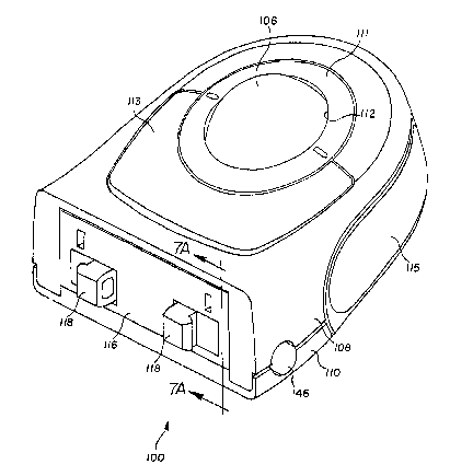
Figures lA and lB show a trackball-type pointing device 100 according
to the present invention. The pointing device 100 includes a housing 102 with a
coupling assembly 104. As shown in Figures SA, SB, 6A and 6B, the housing 102
supports a ball 106 and associated circuitry to provide input signals to a computer
35 (shown in Figure 6B). Although a trackball is described below, the present invention
may be used with any input device or other peripheral device usable with a computer.
The coupling assembly 104 is selectably attachable to, and detachable from, the
212~)~35
computer. The computer, to which the coupling assembly is attached, supports theentire weight of the pointing device 100 when it is attached thereto. The housing 102 is
pivotably coupled to the coupling assembly 104 for rotation or tilting relative to the
coupling assembly and hence, relative to the computer.
S Although the pointing device 100 of the present invention is described as
attachable to the computer, the term "computer" as used herein, means any component
part of a computer, including, the primary housing, the keyboard, the CRT, or other
computer device. Additionally, the pointing device 100 may be attachable to any
surface requiring the use of a pointing device. For example, the present invention may
10 be attachable to an automatic teller machine, video game, or other device requiring
input from a user. Moreover, although the present invention is shown and described
below as being removably attached to a computer, it is contemplated that the present
invention may be fixedly attached to a computer.
The housing 102 includes an upper housing 108 and a lower housing
15 110. The lower housing 110 forms the major bottom surface of the pointing
device 100, and the upper housing 108 forms the major upper surface of the pointing
device 100. The ball 106 shown in Figures 5A-6B extends upwardly and through a ball
aperture 112 in the upper surface of the upper housing 108. A retaining ring 111 retains
the ball 106 in the housing 102. Input buttons 113 and l l S are provided on the housing
20 102. The upper housing 108 and the lower housing 110 together form a front surface,
left and right side surfaces and a curved rear surface of the housing 102. The upper
housing 108 and the lower housing 110 may be joined together by any number of
connection means known by those skilled in the art. Figures IA and IB show, for
example, portions of screw apertures 114 to permit appropriate screws to securely join
25 the upper housing 108 with the lower housing 110.
The coupling assembly 104 is located within and at the front of housing
102 and includes a coupling frame 116. Within recesses in the coupling frame 116 are
a pair of gripping members 118, respectively. The gripping members 118 preferably
have oppositely projecting tabs 120 which permit the coupling assembly 104 to
30 selectably attach to, and detach from, a computer. The tabs 120 project forward and
outward through a rectangular aperture 121 defined in the front surface of the housing
102.
A spring 122 biases the gripping members 118 and their tabs 120 away
from each other. The tabs 120 are sized to releasably engage correspo~ ding flanges in a
35 computer, preferably positioned within a recess in the side of the computer, such as the
computer's keyboard or its housing, shown in Figures SB and 6B. The gripping
members 118, and the associated members (including the spring 122 and the tabs 120)
2 1 2 ~
may be of any design which permits the pointing device 100 to selectively attach to,
and detach from, a computer. As noted above, screws, snap fit or other means may also
be used to fixedly attach the coupling frame 116 to the computer when removability is
not required. When attached to the computer, the coupling frame 116 is held stationery
S with respect to the computer. Further details on apparatus for removably coupling a
device to a computer are described in U.S. Patent No. 5,187,468, incorporated herein by
reference.
A rod 124 extends laterally through a pair of rod apertures 126 in right
and left sidewalls 128 and 128', respectively, of the coupling frame 116. The gripping
10 members 118 are slidably mounted on the rod 124 and the rod extends through the
spring 122 to secure the gripping members 118 and the spring 122 within the coupling
frame 116.
The coupling frame 116 has a pivot blade or hinge plate 130 fixedly
attached thereto by any appropriate means, including glue, screws, etc. The hinge plate
15 130 has an elongated upper edge portion 132 which is rotatably received within a
laterally extending, do~vnward opening recess 134 in a hinge pocket plate 136 fixedly
attached by any appropriate means, including glue, screws, etc., to the upper housing
108 and projecting over the hinge plate. The line of contact between the hinge plate
130 and the hinge pocket plate 136 defines a laterally extending axis of rotation about
20 which the housing 102 is pivoted or hinged relative to the coupling assembly 104. The
hinge pocket plate 136 is attached to an inside surface of an upper wall of the upper
housing 108 so as to position the axis of rotation within the housing 102. Together, the
hinge plate 130 and the hinge pocket llS form a knuckle joint assembly 138. Those
skilled in the art recognize, however, that other joints or hinges may be substituted so
25 long as they provide the same pivoting function, e.g., piano hinges. The joint assembly
138 permits the housing 102 to pivot about the hinge plate 130 of the coupling
assembly 104. The joint assembly 138 is positioned at the top of the pointing device
100, relative to the work surface.
The coupling frame 116 and the hinge plate 130 may be manufactured
30 together as an integral piece. Likewise, the upper housing 108 and the hinge pocket
plate 136 may be manufactured as an integral piece. In the illustrated embodiment of
the invention, the hinge plate 130 and the hinge pocket plate 136 of the joint assembly
138 are composed of stainless steel and the housing 102 and the coupling frame 116 are
composed of plastic. The hinge plate 130 is a long rectangular plate, securely attached
35 to the top of the coupling frame 116, having its upper edge portion 132 above the top of
the coupling frame 116. The hinge pocket plate 136 is a separate steel componentsecurely attached to the underside of the upper housing 108. The joint assembly 138 is
212 ~ ~ 3 ~ ~
made of stainless steel to reduce wear at the hinge point, provide increased strength,
and to provide a lower coefficient of friction at the hinge point.
Located within the housing 102 is an aGtuator assembly 140 which
allows selective rotation of the housing relative to the coupling frame 116 of the
5 coupling assembly 104. The actuator assembly 140 includes a pair of opposed right
and left pivot button members 142 and 142', respectively. The pivot button members
142 and 142' each include a button plate 144, a pivot button 146, and a locking member
148. The button plate 144 has a substantially flat rectangular portion 150, and a flat
semicircular portion 152 extending upwardly from the laterally outward short end of the
10 rectangular portion. The pivot button 146 is mounted on the laterally outward side of
the semicircular portion 152. The bottom surface of the rectangular portion 150 is flat
andconfiguredtorestonaflatinnersurface 153 ofthelowerhousing 110.
The locking member 148 is fixedly attached to and carried atop of the
rectangular portion 150 of each of the pivot button members 142 and 142'. A spring tab
15 154 is fixedly attached at a laterally inward end of the rectangular portion 150. The
spring tab 154 extends slightly upward from the rectangular portion lS0. The spring
tabs 154 of the two-pivot button members 142 and 142' are positioned opposite each
other and have a spring 156 inserted therebetween. l~ach of the spring tabs 154 projects
partially into and retains one end of the spring 156. The spring 156 biases the pivot
20 button members 142 and 142' in opposing, laterally outward directions.
The housing 102 has right and left button apertures 158 and 158',
respectively, with the pivot button 146 of the corresponding right or left pivot button
members 142 or 142' extending therethrough. Preferably, the pivot buttons 146 are
positioned near the bottom surface of the lower housing 110. The pivot buttons 146 are
25 positioned opposite to each other to permit a user to single-handedly actuate the pivot
buttons by pressing them inwardly, with respect to the housing 102, and toward each
other.
A button member guide 160 slidably retains the pivot button members
142 and 142' against the lower housing 110 and guides their movement when the pivot
30 buttons 146 are pressed by the user, and when the spring 156 returns them to their
original position. The button member guide 160 has right and left locking apertures
162 and 162' with a corresponding one of the locking members 148 of the pivot button
members 142 and 142' projecting upwardly therethrough. The button member guide
160 also has right and left, laterally extending slots 164 and 164' with a corresponding
35 one of the spring tabs 154 of the pivot button members 142 and 142' extendingtherethrough. The locking member apertures 162 and 162', and the spring tab slots 164
and 164' have a size greater than that needed by the locking members 148 and spring
:'''': ~',
212~3~
tabs 154 to permit the pivot button members 142 and 142' to move laterally back and
forth within the housing 102.
As shown in Figure IB, the button member guide 160 includes, on its
lower surface, several tabs 166. As shown in Figure IA, the lower housing 110
S includes several tab recesses 168 designed to receive and snap fit the tabs 166 so as to
hold the button member guide 160 in place within the housing 102. The pivot button
members 142 and 142' are positioned between the lower surface of the button member
guide 160 and the flat inner surfaces 153 of the lower housing 110 when the tabs 166
are positioned within the tab recesses 168. When the pivot button members 142 and
142' are so secured, and the spring 156 in position between the spring tabs 154, this
portion may be more easily assembled with the other portions of pointing device 100.
The button member guide 160 moves with the housing 102 and has a
curved upper surface 167 against which a curved lower side 169 of the coupling frame
116 slidably fits. With the arrangement described, the housing 102 is clamped around
the coupling frame 116. Downward movement of the coupling frame relative to the
housing is restricted by the lower housing 110 and the button member guide 160, while
upward movement of the coupling frame relative to the housing is restricted by the
hinge plate 130, hinge pocket plate 136, and upper housing 108. As shown in Figures
7A and 7B, this effectively retains the hinge plate 130 and the hinge pocket plate 136 in
constant compression as the housing 102 is rotated.
In the preferred embodiment, the button member guide 160 is made of,
or coated with, a material selected to reduce friction between itself and the coupling
frame 116 as the housing 102 is pivoted about the hinge plate 130 of the coupling
assembly 104. For example, TEFLONt~) anti-friction coating, manufactured by DuPont
Corp., may be used on the upper surface of the button member guide 160, the surface
which contacts the coupling frame 116. Those skilled in the art will recognize that the
button member guide 160 may be made from, or coated with, any suitable material to
reduce friction, and that the choice of material to be used may depend upon the type of
material of which the coupling frame 116 is manufactured.
The housing 102 is rotatably attached to the coupling assembly 104 by
the joint assembly 138 (i.e., the hinge plate 130 and the hinge pocket plate 136) for
rotation about the axis of rotation defined by the hinge plate 130 and the hinge pocket
plate 136. As shown in Figures 7A and 7B, the axis of rotation, and thus joint assembly
138, is preferably located at the upper, forward edge of the upper housing 108
(proximate to, e.g., the computer keyboard) to which the pointing device 100 is
attached, but inside the housing 102. The locking members 148 selectively engage and
interlock with corresponding portions of right and left fixing members 170 and 170',
212~83~
respectively, each formed in a recess 172 in the underside of the coupling frame 116, as
shown in Figure IB. In one preferred embodiment, the fixing members 170 and 170'each comprise a row of teeth and each locking member 148 comprises a pair of teeth
which mesh with the teeth of the fixing members 170 and 170'. Figures 8A and 8B
show the locking member 148 both engaged, and disengaged with the fixing member
170, respectively.
The user can change the angular orientation of the housing 102 of the
pointing device 100, while it is rigidly attached to the computer, by rotating the housing
about the hinge plate 130 and hinge pocket plate 13G axis of rotation. This is
accomplished by simultaneously depressing both of the pivot buttons 146 of the
actuator assembly 140 inwardly, which causes the pivot button members 142 and 142'
to move inwardly relative to the housing 102, and toward each other. This causes the
spring 156 to compress and the teeth of the locking members 148 of the pivot button
members 142 and 142' to disengage from the rows of teeth of the fixing members 170
and 170', as shown in Figure 8B. With the locking members 148 so disengaged, thehousing 102 can be freely rotated or tilted to the angular orientation desired and then
the pivot buttons 146 released. Of course, the extent of angular movement of thehousing 102 possible is limited by the curvature of surface 169 and the length of the
rows of teeth comprising the fixing members 170 and 170'.
The spring 156 applies a laterally outward force on the pivot button
members 142 and 142' to move the teeth of the locking members 148 back into
engagement with the rows of teeth of the fixing members 170 and 170' when the
buttons 146 are released. The spring 156 retains the pivot button members 142 and
142' in position with the locking members 148 interlocking with the fixing members
170 and 170', as shown in Figure 8A, until the user again depresses the pivot buttons
146 to change the angular orientation of the housing 102. Once the locking members
and fixing members reengage, the housing 102 is held fixed in its new angular
orientation.
The combination of the concave shape of the upper surface of the button
member guide 160 and the complimentary convex shape of the lower side 169 of thecoupling frame 116 permits the teeth of the locking members 148 to always mesh with
the teeth of the fixing members 170 and 170' at any permitted angular orientation of the
housing 102.
The pivot buttons 146 are arranged along a line extending therebetween
which is parallel to the axis of rotation. This line is preferably at a distance of 0.7 cm to
1.5 cm from the axis of rotation of the joint assembly 138. This distance provides a
slight mechanical lever arm to permit the user to easily pivot the housing 102 about the
: :' ,"' :~.
2~ 2S~3~ ~
axis of rotation by applying a force through his fingers engaging the pivot button. This
distance could be increased, however, this would unnecessarily increase the size of the
pointing device 100.
The housing 102 can be rotated to selected angular positions, ranging,
S for example, between one that is substantially horizontal with the work surface and one
that is approximately 60 from the work surface. The housing 102 can freely rotate up
or down until the locking members 148 abut one of the end walls of the recess 172 in
which the fixing members 170 and 170' are forrned, or until its range of motion is
limited by the computer to which it is attached.
The number of possible locking angular positions depends upon the size
and number of teeth used for the locking members 14g and the fixing members 170 and
170'. The locking members 148 each preferably has two teeth and the fixing members
170 and 170' each preferably has seven grooves forrned by its teeth. Therefore, the
housing 102 may pivot and lock in six discrete positions. If only one tooth was used
lS for each of the locking members 148, seven discrete positions would be available;
however, the housing 102 would be held in place at each end by only one tooth, which
might not be sufficiently strong to resist the normal forces applied to the housing during
use, and the tooth might break. Three or more teeth used for each locking member 148
would be even stronger than two, however, fewer discrete positions would be available
20 to the user.
In the preferred embodiment, the housing 102 has a total range of
motion of 30. Since six discrete positions are available, the housing 102 may be
pivoted and retained in 5 intervals. Figure 5A and SB show the housing 102 in a 0 tilt
position; while Figures 6A and 6B show the housing 102 in the fully pivoted 30
25 position.
A first alternative embodiment of the pointing device 200 according to
the present invention is shown in Figures 2A and 2B. The pointing device 200 is
substantially similar to the pointing device 100 shown in Figure lA and 2B, and
elements in Figures 2A and 2B and in the other drawings for other alternative
30 embodiments will be similarly numbered when of similar construction. Only the differences in construction will be described in detail.
A notable difference between the embodiment shown in Figures lA and
I B and the first alternative embodiment of Figures 2A and 2B is the elimination of the
button member guide 160. The button member guide 160 is unnecessary because in
35 this first alternative embodiment, the lower housing 110 has a raised lip 201 at its front
face and a guidebar 203 projecting upwardly from the inner surface 153 of the lower
housing and extending parallel to the lip 201. The lip 201 and the guidebars 203
- 712~3
I l
slidably retain the pivot button members 142 and 142' therebetween. The flat front and
back sides of the pivot button members 142 and 142' slidably rest between the lip 201
and the guidebar 203, to allow lateral movement in response to depressing the pivot
buttons 146 and the retum action of the spring 156.
Each pivot button member 142 and 142' include a button plate 144
having a curved upper surface which slidably contacts the curved lower side 169 of the
coupling frame 116. The lower surfaces of the pivot button members 142 and 142' are
flat to permit these button members to lie in substantially complete contact with the flat
inner surface 153 of the lower housing 110.
Although the two embodiments just described use teeth to selectively
Iock the housing 102 in six discrete positions, in a second alternative embodiment of
the pointing device 300 shown in Figures 3A and 3B, the toothed locking members 148
and fixing members 170 and 170' are replaced with a friction brake arrangement. As
shown in Figures 3A and 3B, a suitable high-friction material covers resilient right and
l S left friction tabs 363 and 363' respectively, carried by the button member guide 160. A
laterally outward edge of each of the friction tabs 363 and 363' is pivotally connected to
the button member guide 160 for pivotal movement or deflection toward and away
from the lower side 169 of the coupling frarne 116. Preferably, a friction material
known as ENDURTM, manufactured by Rogers, Inc., of Connecticut, is applied to
friction tabs 363 and 363'. Those skilled in the art will recognize, however, that any
suitable material with a high coefficient of friction may be used. Alternatively, the
button guide 160 could be entirely manufactured of a material having a high coefficient
of friction.
The friction tabs 363 and 363' preferable have a generally rectangular
shape and bend upwardly when an upward force is applied to their undersides. As
shown in Figure 3A, pivot button members 142 and 142' each have a camming member348 and 348' attached thereto. The camming members 348 and 348' slope downwardlyin the laterally outward direction. When the spring 156 biases the pivot button
members 142 and 142' laterally outward, the sloping upper surface of the cammingmembers 348 and 348' force the friction tabs 363 and 363' upward and into frictional
engagement with the curved lower side 169 of coupling frame 116. The friction
between the friction tabs 363 and 363' and the lower side 169 of the coupling frame 116
is sufficient to lock housing 102 against rotational movement relative to the coupling
frame, thus maintaining the angular orientation of the housing, under the norrnal forces
applied to the housing during use of the pointing device 300.
If a user desires to change the orientation of the device 300, the user
depresses the pivot buttons 146 inwardly and toward each other. This action moves the
. .
:. ~
~12~835
12
camming members 348 and 348' away from engagement with friction tabs 363 and 363'
and into apertures 362 and 362' which are ~ormed in the button member guide 160.Since the friction tabs 363 and 363' are no longer forcibly engaged with the lower side
of the coupling frarne 116 when in the apertures 362 and 362', the housing 102 may be
5 freely pivoted about the rotational axis of the hinge plate 130 and the hinge pocket plate
136. When the desired angular orientation of the housing 102 is reached, the user
simply releases the pivot buttons 146, allowing the spring 156 to force the camrning
members 348 and 348' back underneath the friction tabs 363 and 363', respectively.
This, in turn, forces the upper surfaces of friction tabs 363 and 363' upwardly and again
10 into engagement with the lower side 169 of the coupling frame 116. With thisarrangement for the pointing device 300, infinite angular adjustment of the housing 102
throughout its entire range of motion may be achieved, and adjustment is not limited to
six discrete positions as with the two embodiments previously described.
A third alternative embodiment of the pointing device 400 is shown in
15 Figures 4A and 4B using a ratchet adjustment mechanism. In this embodiment, the
fixing members 170 and 170' within the recesses 172 in the curved lower side 169 of
the coupling frarne 116 each comprise a single row of ratchet or sawtooth-type teeth.
Unlike the symmetric teeth used in the first two embodiments, these ratchet teeth are
asymmetric, having a right triangle-type shape, each row having an opposing
20 orientation from the teeth of the other row. The locking members 148 of the pivot
button members 142 and 142' comprise an opposing pawl such that one is angled in a
generally forward direction while the other is angled in a generally rearward direction.
Each pawl is designed to work with a corresponding one of the ratchet teeth rows.
When the spring 156 biases the pivot button members 142 and 142'
25 laterally outward, the pawls of the locking members 148 are held in locking
engagement with the ratchet teeth of the fixing members 170 and 170'. This locks the
housing 102 in a desired angular orientation, with rotational movement in one direction
restricted by the right pawl and row of ratchet teeth it engages, and rotationalmovement in the opposite direction restricted by the left pawl and row of ratchet teeth it
30 engages. When the user desires to change the angular orientation of the housing 102,
only one or the other of the pivot buttons 146 needs to be depressed, depending on the
direction of rotation of the housing desired. By depressing the right pivot button 146,
the right pawl disengages from the right ratchet teeth, thereby permitting the housing
102 to be pivoted upwardly. It is noted that the left pawl and the left ratchet teeth slip
35 relative to each other when the housing is pivoted upwardly. When the user releases
the right pivot button 146, the housing 102 is locked in the desired angular orientation
- 212S83~
13
against further upward rotation by the right pawl again engaging the right ratchet tèeth.
Rotation downward is prevented by the left pawl engaging the left ratchet teeth.Similarly, when the user desires to pivot the housing 102 downwardly,
the left pivot button 146' is depressed so that the left pawl disengages the lef[ ratchet
5 teeth, thereby permifflng the housing 102 to be pivoted downward. It is noted that the
right pawl and the right ratchet teeth slip relative to each other when the housing is
pivoted downwardly. When the user releases the left pivot button 146', the housing 102
is locked in the desired angular orientation against further downward rotation by the left
pawl again engaging the left ratchet teeth. Rotation upward is prevented by the right
10 pawl engaging the right ratchet teeth. If both pivot buttons 146 are depressed, both the
left and right pawls are disengaged from their corresponding ratchet teeth which allows
free rotation of the housing 102 both up or down.
The pointing device 400 of Figures 4A and 4B permits unidirectional
angular movement of the housing 102 when only one of the pivot buttons 146 is
depressed, but bidirectional movement when both pivot buttons are depressed
simultaneously. Those skilled in the art appreciate that additional pawl teeth may be
added to improve the strength of the mechanism for static position retention.
The pointing device 100 is shown fully assembled in various angular
orientations in Figures SA,5B, 6A, and 6B. As shown in these figures, the housing 102
has a slightly arcuate shape, curving upwardly and away from the work surface.
Consequently, when pointing device 100 is in its 0 tilt position, it is still angled toward
the computer to which it is attached and away from the work surface. This tends to
bring the ball 106 closer to keys 5~9 of the computer. As the pointing device 100 is
rotated upwards to the full 30 position, the body 106 is oriented 60 from the work
suIface, which brings ball 106 quite close to the keys 549 of the computer keyboard
(shown in Figure 6B). Thus, the combination of the upwardly curving body 106
combined with the joint assembly 138 positioned near the top front edge of the pointing
device 100 positions the ball 106 closer to the keys, and thus closer to a user's hands on
the keys than prior art pointing devices.
The combination of the curved housing 102 and the position of the joint
assembly 138 also permits users with various sized hands to use the pointing device
100. For example, a user with large hands would rotate the pointing device 100 to its
more vertical orientation (Figures 6A and 6B), while a user with smaller hands would
orient the pointing device 100 to the more horizontal position, a position more parallel
to the work surface (Figures 5A and SB).
The lower surface of the lower housing 110 has a convex pad 5~5,
preferably composed of rubber, or other similar non-slip material. A cormecting cord
- 212~35
14
547, for COMecting the pointing device 100 to a computer or other device, protrudes
from the pad 545. The pad is comprised of a material more resilient than that ofhousing 102. The non-slip resilient material provides the user with a more positive grip
on the pointing device 100.
Based on the above disclosure, those skilled in the art will recognize that
the present invention places the pivot axis proximate to the computer to which the
pointing device is attached. Additionally, those skilled in the art will recognize that the
present invention employs less components than similar prior att devices. Moreover,
the present invention provides a more compact pointing device than those currently
1 0 available.
Although specific embodiments of the invention have been described for
purposes of illustration, various modifications may be made without departing from the
spirit and scope of the invention, as is known by those skilled in the art. Accordingly,
the invention is not limited by the disclosure, but instead its scope is to be determined
entirely by re-ference to the following claims.
. ... , - ,.. ~ , .. -