Note : Les descriptions sont présentées dans la langue officielle dans laquelle elles ont été soumises.
23.2~97~ 1
WO93/12406 PCT/SE92/00856
FLOWMETER
.
TECHNIC~L FIELD
S The present invention relates to a f lowmeter which is
adapted to enable the total fluid flow through a
conduit to be measured, this conduit being referred to
hereinaf ter as tlle main conduit .
The invention can also be applied to measure the pre-
vailing rate of flow, although for the sake of sim-
plicity, the f lowmeter will be described herebelow
with reference solely to its alternative function of
measuring the total f luid f low .
The invention is a further development of a f lowmeter
which utilizes a flowmeter constriction arranged or
inserted in a section of the main ce:~nduit, a measuring
conduit which extends parallel with the main conduit
2 0 section and is connected across the constriction,
wherein a subf low is caused to pass through the mea-
suring conduit in response to the pressur2 dif f ~rence
across the ccsnstriction caused by the rate o~ f low in
the main c:onduit section, ~a subflow meter conneted in
the ~seasuring conduit, and an elec~ric signal conv~rt-
er with associated correction unit constxucted to
convert a signal delivered by the subflow meter to a
proportional signal:which corresponds to the total
flow through the~main conduit and which is applied to
a flow registering or~flow presentiny means. i f
: It will be understood;that with flowme~ers of this
~ kind, the fl~w measured in a measuring conduit will
; always hsve a given primary relationship with the
total flow through the main condui~ and a given sec-
ondary relationship with the flow passing through the
flowmeter of which said conduit section forms part.
This:first, primary relationship is the relationship
significant to the present invention.
WO93/12406 ~ PCT/SE92/00856
BACKGROUND ART
Flowmeters of the aforedescribed kind are known to the
art and can be re~erred to as "by-pass flowmeters",
since a determined part of the instant, total flow
through the main conduit is caused to pass through the
measuring conduit and the volume of this flow is
determined and is proportional to the total flow
through the main conduit. These known flowmeters
include a larger or smaller fixed throttling orifice
in the main conduit section, and the measuring
conduit, or branch pipe, connected in parallel across
the constriction includes a flowmeter which delivers a
signal corresponding to the flow (or rate of flow)
through the measuring conduit.
For the sa~e of simplification, this signal is exem-
plified in the following description as one pulse per
unit of volume passing through the measuring conduit.
A measured frequency multiplied by the volume unit can
th~ be considered~proportional to the by-pass flow or
the percentage~of~flow throUgh the subflow meter and
therewith, with~a~:~chosen constant, also proportional
: 25 to the total flow through the main conduit.
. ~ ~
The pressure difference occurring:across the throttle
will increase with:~increasing flow through the
throughflow area~:of the throttle and therewith drive
~0 the~by-pass flow through thelmeasuring conduit and the
measuring device and through the main conduit section
~: of the flowmeter. :~
It is Xnown that~a maxinized, accepted pressure dif-
ference and flow rate in the measuring conduit and
~: through the subfIow meter is applicable to a maximum
total flow through the main conduit.
It:is also known to use the same ~y-pass meter for
WO93/1~06 ~ 9 7 6 PCT/SE92/00856
different measuring ranges, by appropriately dimen-
sioning the cross-section of the main conduit and the
size of the throttle in accordance with a chosen
measuring range.
Among other things, it is necessary to afford each
fl~wmeter with the large5t possible measuring range or
dynamics, as will be explained more precisely in the
following.
In the case of a by-pass meter of the type intended
here and described in some detail in the aforegoing,
it is known that when the resistance coefficient of
the throttlQ and the measuring conduit together with
the by-pass meter are equal and the flow is ~urbulent,
the ratio of the flow through the throttle to the flow
through the measuring conduit will be constant, and
that the si~nal delivered by the flowmeter in the
measuring conduit will be proportional to the sum of
both flows.
The British Patent Specific~tion 2257/1886 discloses
an arrangement~which includes a ~y-pass meter and a
variable throttle.~Since this throttle is located
downstream of the by-pa 6 meter where;the u~measured
~ain flow and the ~easured:by-pass flow combine to
- form a common flow,~the ratio of the main f~ow to the
by-pass flow is no~afPected by~the throttle. The
throttle is obtained with the aid of a pivotally
suspended flap w~ich is constructed to maintain a
constant proportionality b~tween measured and unmea-
sured wa~er flows,: irrespective of the instant posi-
: ~ tional setting of the flap~ `
: 35 The flap functions ~o urge the measuring flow throughthe by-pass meter, which is comprised of an impeller t
in response to the pressure exerted thereon ~y the
main flow, which results in an unequivocal ratio
between the occurrent pressure and the generated
WO~3/12406 ~21~ 7 ~; PCT/SE92/008~6
measuring 1OW with unchanged low flowmeter dynamics.
Practical tests performed on the known by-pass
f1owmeters haYe normally shown a flowmeter dynamic in
the order of 50:1. A flowmeter dynamic in the order of
100:1 is most unusual if it can be achieved at all
with good linearity while ~atisfying other general de-
mands.
It is well known to the person skilled in this art
that the advantage~ afforded by by-pas~ meters of
hitherto known construction reside in the possibility
to construct large flowmeters adapted to large volumes
at l~w costs, and that one disadvantage of such flow-
meters resides in their excessively restricted flowme-
ter dynamics.
Also belonging to the earlier standpoint of techniques
with regard to the inventive flowmeter are ~lowmeters
which function according to other concepts, namely
flowmeters which lack a measuring conduit through
which a b~-pass passes.~ : :
According to one embodiment of this latter flowmeter,
a restriction is~used in the main conduit and f~ow is
measurèd by en~ing:the instant pressure difference
between occurrent:~pressures~on each~side of ~he con-
striction~
In a flowmeter of this kind,:the flow detected by the
meter is propsrti~nal to the square r~ot of the
: pressure dif f erence.; :
Flowmeters of~this category have been found to be
`35 highl~ accurate within a pressure difference range of
50:1, which then~gives a flowmeter dyna~ic of only
about 7~ at a: constant throughflow area formed by
the constrîction and o~tained, for instance, by using
an orifice plate, a measuring flange, a measuring
WO93/12406 ~12 ;~ 9 7 ~i PCT/SE92/008S6
nozzle, a Venturi tube or some like device.
While taking into account the requirement of a maxi-
mized, accepted pressure difference across the con-
striction, various measures have earlier been proposedfor attempting to increase the measuring range of the
flowmeter or to increase the flowmeter dynamics ~Qmax-
:Qmin) while ~aintaining the pressure drop (the pres-
sure losses) thorugh the flowmeter at an acceptable
low level.
It is earlier known in this regard to increase flowme-
ter dynamics with the aid of a throu~hflow area which
is dependent on the instant flow and which is there-
fore variable. The measuring device connected to thesystem still measures the flow as a function of the
occurrent pressure drop across the constriction.
In the case of such pressure difference flowmeters, it
is known to determine the occurrent, instant pressure
drop with the aid~of a pressure differential transmit-
ter.
It is also earlier known that flowmeter dynamics can
be improved when.the variable throughflow area is per-
mitted to increase~with increasing pressure differ-
ence, and vice versa.~This is achieved with the aid of
an axially movable~ and spring-biassed throttling body
placed in the main~conduit, for instance a flow throt-
tling body of the kind illustrated and described inBritish Patent Specification l,566,251. In this re-
gard, it has been found that the fIowmeter dynamics
; can be increased to an order of magnitude of 50:l.
: ` :
35 Finally, it can be~mentioned that it is known that the
dynamics of a flowmeters can be increased ~y up to
50:l when an inductive transducer is used directly in
the main conduit. However, this increase in flowmeter
dynamics is obtained at the cost of the possible
WO 93/12406 ~ J ~ ~ PCI /SE92/00856
choice of the f lowing medium, since an inductive
transducer requires the presence of an electrically
conductive medium.
It is also known to detect the output signal from dif-
ferent measu~ing devices with the aid of electronic
signal converters and to convert the signal to a
proportional signal correspondin~ to a total medium
flow, in accordance with a mathematical fun~tion.
It is possible to introduce minor corrections to the
signal with the aid of these electrical signal con-
verters, so as to compensate for minor deviations from
sufficiently accurate proportionality.
DISCLOSURE OF THE INVENTION
TECHNICAL PROBLEMS
When considering the present :standpoint of techniques
as described above with reference to known fundamental
principles for measuring~the total flow through a main
conduit it will be seen that one qualified technical
pro~lem resides in realising the significance of
providing on the:basis of a by-pass flowm~ter, a
flowmeter ,which will measure flow accurately and which
will pro~ide a~flow~measuring dynamic:which is
considerably greater~than the dynamic hitherto
afforded by the known flow measuring syste~s described
above.
A still more qualified:technical problem is one of
realizing the significance of further de~eloping the
: fundamental oonditions and principles of the by-pass
. meter so as to enable the meter to utilize all types
of 10wmeters in its measuring conduit and to make
corrections which:not only take into consideration the
measuring device but also the instant or current
throughflow area.
WO93tlZ406 ~J ~ 5 ~ 7 ~ PCT/SE92/00856
It will al50 be seen that a technical problem resides
in realizing, among other things as a first step
towards the object of providing a flowmeter which wlll
solve the aforesaid technical problems, that tbe by-
pass meter shall be complemented with a flow-depen-
dent, ~ariable throughflow area, in principle previ-
ously known in differential pressure flowmeters.
It will also be seen that a technical problem is one
of realizing that a second step towards the object of
providing a flowmeter which solves the aforesaid
technical problems is a sociated with the p~ssibility
of li~earizing the measuring signals obtained from the
subflow meter, so that subsequent being corrected as
required, the signal can represent the proportionality
to the total flow through the main conduit within a
large flowmeter dynamic, for instance a dynamic above
1000: 1 ~
In the case of a by-pass meter of the kind described
in the introduction and complemented in accordance
with the aforegoing, it will be seen that a technical
problem resides in realizing the possi~ility of using
a less stringent mathematical relationship between a
signal~obtained from the:subflow meter and a prevail-
ing total flow:,~wherein a conical body disposed in the
: main conduit is:intended to provide a greater through-
flvw area;in~xesponse to:~increasing pressure ~iffer-
ences across the constriction, and vice versa.
:~ In this regard, a technical problem resides in the
significance of utilizing the fact that in the event
of a low tota1 flow a relatively large part of this
: flow will pass to the:measuring conduit and that in
the case of a large total flow a relatively smallj
very~small, part of this flow will pass through the
measuring conduit, and therewith to realize that a
large flow of med:ium through the main conduit will
result in a much smaller increase in the by-pass flow
WO 93/12406 ~ 12 S 9 7 ~ PCI/SE92/00856
through the measuring conduit than in the (-ase of a
fixed throughflow area, which experience shows would
result in a proportional increase of the instant flow
through the measuring conduit and ~ice versa.
Against this background, it will be seen that a tech-
nical problem resides in the ability to realize the
significance of using a compensatlng device, normally
included in the electronic signal converter, such as
to compensate the output signal from the by-pass meter
in response to occurrent discrepancies in a manner to
achieve precise proportionality with the instant total
flow through the main conduit.
It will also be seen that a technical problem is one
of realizing the significance of configuring the
aforesaid conical body a~ more or less a truncated
conical body with the:cone apex pointing towards the
flow directio~ in the m~ain conduit, and permitting the
conical body to be axially movable in relation to a
fixed throttling~plate as~to define a given
throughfIow area~which~is related to the instant fl~w..
It will also be een that a:technical problem resides
:
in realizing th:e~significance of utilizing in this
application a spring~device which is active in urgin~
the conical body in~:a~direction towards the throttle
disc or plate with:an adapted force, so as to displace
the conical body towards the~formation of s~aller
throughflow areas~as the flo~ decreases.
~.: : ~ :
Another technical proble~ is one of realizing the sig-
~ ~ nificance of adapting the force exerted by the spring
: 35 device to a ~alue~which corresponds to a selected
~ maximum flow through the main conduit and the main
: conduit section when its narrowest part is located in
or adjacent to a plane of the throttle or constriction
at said maximum ~low.
WO~J3/l2406 ~1 2 t3~ 7 ~ PcT/sE92/no8s6
Finally, it will be seen that a technical problem re-
sides in realizing the significance of using an elec-
tronic signal converter which is so constructed that
subse~uent to calibration it will convert each occur-
rent flow in the measuring conduit and the corre-
sponding output signal of the by-pass flowmeter to a
value which corresponds to the instant total flow
through the main conduit.
SOLUTION
The present invention is intended to solve one or more
of the aforesaid technical problems on the basis of a
flowmeter of th~ kind which utilizes a constriction
which is disposed in a main-conduit section and which
defines a throughflow area therein, a measuring con-
duit which is connected in parallel across the con-
striction, wherein a by-pass flow is caused to pass
through the measuri~g conduit by the pressure
difference across the constriction caused by the flow
in the main-conduit section, a measuring device
connected in the measuring conduit, and an electronic
: signal converter which functions to convert a signal
delivered by the measuring:device to a:signal which
corresponds to the total~flow through the main
conduit. ~:
It is proposed~that the area~ of the main-conduit con-
striction is regulated-by~:a conical body which is
disposed in the~main conduit such as to produce an in-
creasing :
:` throughflow area in response to an increasing pressure
~; difference across the:constriction or an in~reasing
flow through the throughflow area, or vice versa. -
~ 35 . ~ ~
The~use of a movable conical body in a fixed constric-
; tion will result in an increasing instant flow through
the main conduit, due to the concurrent movement of
the conical body, such that in the event of a large
~: .
W~93/12406 2 ~ 2 ~ PCT/SE92/00856
flow, the instant flow through the measuring conduit
will increase to a lesser extent than would otherwise
be the case when the throughflow area of the constric-
tion is fixed, which seen practically results in
S precise proportionality (without a conical body and a
fixed constriction or with a fixed conical body).
Furthermore, the use of a conical body which is move-
able in a fixed con5triction necessarily implies the
use of a complex compen5ating device, normally inte-
grated with the electronic signal converter, so adapt-
ed as to be capable of fully compensating a signal
obtained from the by-pass flowmeter in response to
occurrent, instant discrepancies, to proportionality
to the total flow through the main conduit.
~orrespondingly, although conversely, an adjustment or
adaptation takes place at decreasing instant flows.
By way of suggested embodiments that fall within the
scopP of the inventive concept it is proposed that the
conical body shail have a truncated, or at least
essentially truncated, conical configuration, with the
cone apex pointing towards the flow direction in the
main-conduit section t and that the conical ~ody is
: 25 mounted~for movem~nt in relation to a fixed constric-
tion.
It is also propoæed~that a spring device is provided
for urging the conical body in a direction towards the
fix2d constriction in an adapting fashion, by adapting
the force exerted by the spring device in accordance
with selected minimum and maximum flows through the
~: main conduit.
. F~nally, it is proposed that the aforesaid electronic
signal converter is constructed to assign, through
calibration, to each selected by-pass flow measured in
the flowmeter a value which corresponds to the pre-
vailing or instant total flow while taking the posi-
W O 93/12406 2 i2 3 97 ~i PCT/SE92/00856
tional setting of the conical body into account.
ADVANTAGES
The advantages primarily afforded by the inventive
flowmeter reside in the creation of conditions which
enable the dynamic of a flowmeter which operates in
accordance with the principles of measuring instant
flow in a measuring aonduit connected in parallel with
a constriction in a main-conduit section to be greatly
i.ncreased, while still providing a flowmeter whose
output signal is linear to the total flow through the
. main conduit, due to a particular compensation facili-
ty afforded by an associated electronic signal con-
verter.
_____ __ ______ .
The primary characteristic features of an inventive
flowmeter are set:forth in the characterizing clause
of the following Claim 1.
BRIEF DESCRIPTIO~L_9E~ ~HE DFU~WINGS
An embodiment which:is at present preferred and which
possesses the charaateristic features significant of
the present invention will now be described and ex-
plained in more detail with reference to the accompa-
nying drawings, in which
. ~igure 1 illustrates~the principles of a flowmeter
which includes a section of a main conduit and which
also includes:a fixed constriction and a measuring
: conduit whic~ is connected in parallel across the con-
striction and in which a by-pass flow is evaluated,
wherein the present invention constitutes a further
: development of the illustrated arrangement;
WO93/12406 ~ PCT/SE92/00~56
12
Figure 2A illustrates a flowmeter constructed in
accordance with the principle of determining occurrent
pressure differences on each side of a fixed constric-
tion in the main conduit;
Figure 2B illustrates the principles according to
Figure 2A when the constriction used has a variable
throughflow area, said throughflow area increasing
wi h larger flows through the main conduit, and vice
versa;
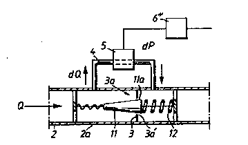
Figure 3 illustrates schematically an inventive flow-
meter which operates in a manner similar to the flow-
meter shown in Figure 1 but which, among other thing~,
has bee~ complemented with the features show~ in
Figure 2B so as to enable the throughflow area to be
varied in response to the instant flow in the main
conduit;
Figure 4 is a diagram which shows a number of curves
representing pressure difference variation in the ab-
sence of compensation in relation to the total flow
for the flowmeter illustrated in Figures 1, 2A and
2B;
. ~ :
Figure 5 is a diagram which includes curves showing
the variation in the by-pass flow in the absence of
compensation a~d with compens~tion, in relation to the
total flow;
~ . i
Figure 6 is a diagra~ showing t~e volume representa-
tion of the by-pass~meter in accordance with known
techniques and in accordanc~ with the inYention in
re}ation to the total:flowj and
: 35
Figure 7 is a diagram showing signal frequency varia
tion in accordance with known techniques and in
accordance with the present invention in relation to
the total flow.
WO 93/12406 ~ 9 ~ ~ PCl/SE92/00856
13
I:)ESCRIPTION OF EMBODIMENTS AT PRESENT PREFERRED
Figure 1 illustrates schematically a flowmeter 1 w~ich
includes a section 2a of a main conduit 2. The conduit
5. section 2a has mounted therein a fixed constriction 3
and a measuring conduit or by-pass conduit 4 is
connected in parallel across the constriction. A pres-
sure difference created across the constriction 3 as a
result of the rate of flow of the medium in the
main-conduit section 2a causes a by-pass flow dQ to
pass through the measuring conduit 4.
. The measuring conduit 4 includes a measuring device 5
to which there is connected an electronic signal
converter 6 which functions to convert the outward
signal of the device 5 to a signal which corresponds
to the total flow~Q passing through the main conduit
2. In the illustrated case, the by-pass flow and main
flow and the signals~are essentially proportional.
The flowmeter l:thus~comprises a section 2a of a main
;~ conduit 2, a fixed:constriction 3 which is mounted in
the conduit section 2a~and which:defines a throughflow
area 3a, a measuring;~conduit 4 which is connected in
parallel ac~oss.the~constriction 3, a measuring device
~: ~ S which is.. connected~to`~the:;measuring conduit and
which can be said~to~del~iver a signal which is
: representative::of:~a~ guantified~by-pass flow-section,
and an electronic~s~ignal ~onverter 6 which functions
to deliver on a line~6a~a.signal which is proportional
to the fIow through~:~the~main conduit 2.
For the sake of:;~simpl;icity, this signal i5 shown as an
electric pulse;representing a quantified by-pass flow-
35: section through the measuring conduit.
The invention is based on the assumption that the
: flowmeter will functlon faultlessly when the measuring
device 5 is comprised of earlier known means, such as
WO93/1~06 ~12 5 t~ 7 6 14 pcr/sE92/oo8s6
a fluidistor oscillator 5a, a rotatable impeller, aninductive meter or similar means. Since these devices
are known to the art they will not be described in
great detail here.
It suffices to say that the device 5 includes a means
(5a) which is able to determine the instant or occur-
rent by-pass flow dQ, by generating a pulse, for
instance an electric pulse, for each determined,
quantified flow part which passes through the
measuring conduit and a corresponding, instant total
flow Q through the main conduit 2 is calculated in
dependence on an evaluated pulse frequency from an
electronic signal converter and by proportionalization
and possibly by a minor correction.
In the case of the Figure l embodiment, the total mea-
suring ratio (Qmax-Qmin) for the flow Q through the
main conduit will be the same~as the total measuring
ratio applicable to the measuring device used. The
flow dynamic (Q~ax-Qmin) with this known technique is
50:l-lOO:l.
It should be noted that this ratio is a general ratio,
irrespective of w~ether the means Sa is a mechanical
meter (impel1er) or;~a fluidistor~oscillator meter.
Figure 2A i}lustrates, in a similar manner, a flowme-
:: :
ter which operates in accordance with other principles
and conditions than those described with reference to
Figure l.
:: ~ :
In the Figure 2A~embodiment, the flowmeter measures
the instant pressure difference Pl-P2 = dP-between the
pressures occurring~pstream and~downstream of a fixed
~- constrict.ion 3' mounted in a main conduit 2' in a
known manner.
The pressure Pl occurring upstream of the constriction
WO93/12406 ~ 3~ 2 3 9 7~ PCT/SEg2/00856
3' propagates through a narrow channel Sa' to a pres-
sure difference meter S', whereas the pr~ssure P2
occurring downstream of the constriction 3' propagates
through a narrow channel 5b' to the pressure differ-
ence meter 5', on each side of a membrane which movesin response to the pressure difference. The membrane
coacts with a signal e~itter 5c' in a known manner.
The illu~trated flowmeter l' includes a known pressure
difference meter 5' which is connected to an el~ctron-
ic signal converter 6'. The electronic siynal convert-
er 6' is constructed to transpose the o~tained signal
. in accordance with a quadratic function and in this
way to deliver on the line 6a' a signal which is
proportional to and which corresponds to the total
flow Q'.
In this case, the achieved flowmeter dynamic will only
be about 7:1.
As Figure 2B is intended to sho~, it is known to
: : introduce a body lO which~when the flow (Q') increases
will increas~ the:~throughflow area, as a result of
being displaced axially in a downstream direction, or
vice versa. Alth~ugh~this~body will result in a non-
linear output signal, it has~been found to increase
the dynamics of the~flowmeter.
Practical experiences indicate that when there is in-
cluded in the main~conduit ~;' a body lO which is able
to move in the direction~of the longitudinal axis of
the mai~n conduit,~the:flow dynamic ~Qmax/Qmin) can
~: reach to 50~ through:the~expedience of measuring the
~ pressure in the conduits 5a'and 5b'.
:~ 35
~: ~
Figure 3 illustrates an inventive flowmeter embodiment
which includes~the~components illustrated in Figure l.
~: The significant feature of the Figure 3 embodiment is
that the measuring conduit 4 incorporates a small
:
WO93/12406 ~ ~ 2! ,5 ~ 7 ~ PCT/SE92/00856
16
flowmeter 5 which is principally of the same kind as
that iilustrated in Figure l.
In this case, the necessary constriction is comprised
of a~orifice plate 3 and a conical body ll which are
mounted in the main-conduit section 2a, such that the
widest part lla of the conir~l body will seal against
the inner edge surface 3a' of the plate 3 in the
absence of flow, such as to present a small or zero
throughflow area 3a.
Starting from a selected flow, it can be established
that as the flow Q increases, the conical body ll will
be pressed to the right so as to increase the through-
flow area (defined by the edge 3a' and the peripheryof the conical body) and that when the flow Q decreas-
es, the conical body ll will be pressed to the left by
means o~ a spring 12, so as to decrease the through-
flow area 3a.
~0
It can als~ be seen from Figure 3 that when the flow Q
through the mai~ conduit 2 is small, the throughflow
area will~also be small or zero, so that all of the
flow, or at least a large part of the total flow
through the main.ionduit 2 will pass through ~he
measuring conduit 4.:
:
When the ~Iow Q through the main conduit 2 is large,
the throughflow area 3a will also be large and a
smaller part dQ of theitotal flow Q will pass th~ough
the ~easuring conduit 4.
These conditions will be seen more cIearly from Figure
6.
- .
The conical body ll is thus intended to increase the
throughflow area in the main conduit in response to an
increasing flow, which results in only a slight in-
crease in the pressure difference in the measuring
WO 93/12406 2 ~ 2 ~ 9 7 ~; PCT/SE92/00856
17
conduit 4, since the conical body 11 is moved to the
right in Figure 3 and the spring 12 is compressed.
This means ~hat the proportional ratio illustrated in
Figure 1 between the subflow dQ in the measuring
conduit 4 and the flow Q through the main conduit 2 no
longer exists.
When the flowmeter includes a constriction 3 and a
conical body 11 mounted in the constriction, the
proportional relationship betw~en sub~low dQ and total
flow Q obtained with a fixed constriction will be
changed such that in the case of a large flow the
subflow dQ will not increase so radically but will be
small through the measuring conduit 4 in relation to
the instant main flow Q through the main conduit
section 2a.
The illustxated conical body ll has a truncated coni-
cal configuration, with the cone apex pointing in a
direction towards the:direction of flow through the
main conduit 2, and is axially movable in the main-
condui~ section 2a~in rel~ation to the fixed constxic-
tion 3 and is positioned:central}y in the conduit
: section 2a.
: A spring device:12~is~active in pressing the aforesaid
: conical body ll towa~r~s the~constriction 3, with the
force exerted~by `~aid~spring means 12 bei~g adapted to
a chosen minimum and maximum flow through ~he main
conduit 2. l:
The minimum flow is that~flow from which the flowmeter
functions, and minimum~flow conditions the conical
ody 11 wiIl normalIy be~:located in a position in
. which its peripheral surface defines a small through-
flow area 3a with the edge surface 3a' of the fixed
~ constriction 3.~ :
: ~
~ ~ At maximum flow, the conical body ll will be located
WO93/12406 ~ ~ 2 r3 9 7 6 PCT/SE92/00856
18
in a position to the right of the constriction in
which it defines a large throughflow area 3a.
The electronic signal converter 6" is also constructed
so that it can assign, via calibratîon, to each evalu-
ated by-pass flow dQ passing through the measuring
conduit 4 a value which corresponds to the inctant
total flow Q (while taking into account the inf luence
of the conical body ll in its current positional
setting).
The curves in the diagram of Figure 4 are intended to
show the dynamics (Qmax/Qmin) of the flowmeter con-
structions illustrated in,Figures l~ 2A and 2B.
The curves are chosen so that Qmax represents a maxi-
mized and same pressure drop dP across the flowmeter
5, 5'.
Curve A is meant to illustrate~the proportional rela-
tionship of the pressure~drop~:with the total flow in
the caæe of a flowmeter according to Figure l.
In practice only a:minor:correction is required in
this case, since the~curve is essential~y a straight
line.
The curv B is intended to illustrate the quadratic
relationship of~the~;~pressure drop with the volume flow
in the case of a subflow meter accoxding to Figure 2A
having a fixed:constriction 3'.
~: .In practice, a mathematical calculation and a correc-
:~: tion are required in:order to achieve proportionality.
::
: ~:
Curve C is intended:to illustrate the relationship
that occurs with a variable throughflow area, in
accordance with Figure 2B.
WO g3/1~06 ~ ~ 2 1~ ~ 7 ~3 PCT/SEg2/00856
19
In practice, an accurate correction is required in
this case in order for the signal to be propoxtional
to the instant total flow.
Figure 5 illustrates a curve D which is representative
of the invention.
Curve D i~ intended to illu~trate the relationship of
the by-pass volume to the total flow volum~ when using
an inventive measuring device, in which the flowmeter
dynamic can be as large as 2500:1.
Figure 5 is intended to illustrate that the output
signal obtained from the subflow meter 5 and which is
not corrected can be considered to follow the curve D,
and that it is therefore necessary to introduce a cor- :
rection towards the straight line represented by curve
D' in order to achieve proportionality between the
obtained output signal and the instant total flow.
The flowmeter dynamic can at least be assu~ed to
exceed lO00:1, and a value of about 1500:1 is ~hought
to be appropriate. It is also believed to be ~ost
appropriate to choose the flowmeter dynamic range
within the limits of 1000.1-2030:1
'
It should be noted in this r~gard t as Figure 5 is in-
tended to show, that the relationship is not a linear
relationship, but that th~ electronic signal converter
6" shall include the necPssary mean~ for compensating
for occurrent deviation~ with sufficiently small
resolution with the aid of a calibrating procedure.
It can be mention~d that the flowmeter ~ynamic may be
~5 -increased to lie within the upper r~nge, by using a
~lowmeter 5 which has an extremely small internal
pressure drop, such as an inductive flow transducer.
The compensation necessary in accordance with the
WO93/12406 21 ~ 5 9 ~ PCT/SE9t/00856
invention will now be explained in more detail with
initial reference to Figure 6. This Figure illustrates
that in the case of a by-pass meter of the kind illus-
trated in Figure l, in which there is precise propor-
tionality between thé flow passing through the measur-
ing conduit and the flow passing through ~he main
conduit, the small by-pass flow or the quantified
subflow'parts ~liter/pulse "l/p") measured in the
measuring conduit 4 is constant, irrespective of the
instant total flow through the main conduit 2.
This is illustrated with a straight line 20 in Figure
6.
lS It,can also be established that an increasing total
flow will result in an increasing by-pass flow through
the measuring conduit, and that the frequency of the
signals delivered by the flowmeter 5 will therefore
increase, and vice versa.
The output pulses of the flowmeter 5 therewith have a
frequency f which varies linearly with changes in the
instant volume flow through the main conduit.
~: 25 This is illustrated with a sloping, straight line 30
: in Figure ~.
When considering:~the:present invention as illustrated
in Figures 6 and~7, it will be seen that the by-pass
flow, or each quantified subflow section l/p measured
in the measuring conduît 4 will represent different
total flows in accordance with the line 21.
Thus, it can be read from Figure 6 that a measured
flow t~rough the measuring conduit 4 within the region
of Qmin represents a small total flow Q. The ratio can
then be set at l:l.
W093/12406 .~1~ 5 ~ 7~i PCT/SE92/00856
21
Depending, among other things, on the configuration of
the conical body, the ratio will increase in accor-
dance with the line 2l with increasing flows Q, such,
that the flow measured in the measuring conduit 4 will
represent a successively greater total flow Q through
the main conduit 2.
A corresponding comparison with Figure 7 will show
that the generated pulse frequency will be greater and
smaller than proportional, in accordance with the line
31.
When comparing with the earlier known construction
shown in Figure l, it,can be said in summary that with
a given total flow Q' through the main conduit 2, the
inventive flowmeter will provide, through correction,
a value Q" which is calculated from a quantified by- '
pass flow part and which is smaller or greater than
that obtained with earlier known constructions and
from a frequency which is greater or smaller than that
obtained with earlier known constructions.
: This means that with an instant flow Q" and with an
increase in the volu~etric flow or instant flow
through the mai~conduit;~2,~thé new instant flow value
wilI result in a~smaller~inorease~in the by-pass flow
dQ through the measuring~conduit~4 than is obtained
:with a fixed constriction,:due to an increase in the
throughflow area.
: ~inally, it will be:noted that the configuration of
: the illustrated conical~body is such as to provide a
~; :; given relationship:between:its axial movement and the
;~ :increase in throu~hflow area, and that this configura-
::~ 35 tion is inexpensive in manufacture.
However, there is nothing~to prevent the conical ~ody
:being given another form which provides another rela-
tionship and affords a smaller electronic compensa-
WO 93/12406 ~12 5 9 7 5 22 PCl`/SE92/00856
tion, although it can be expected that the manufactur-
ing costs will then be higher.
It will be ~nderstood that the invention is not re-
stricted to the aforedescribed, exemplifying embodi-
ment thereof and that modifications can be made within
the concept of the invention as illustrated in the
~ollowing claims.
:
: .