Note : Les descriptions sont présentées dans la langue officielle dans laquelle elles ont été soumises.
~J ~'~38d
10
CANNELLONI PRODUCTION
The present invention relates to a process for the
continuous production of cannelloni.
Cannelloni is traditionally made manually in separate
steps. However, not only is the pasta usually very sticky
and slippery to handle, the process is extremely time and
labour consuming.
We have now devised an automatic mechanical process which
obviates the above disadvantages.
Accordingly, the present invention provides a process for
the continuous production of cannelloni which comprises
a. forming a blanched, pasta strand,
b. cutting the blanched, pasta strand longitudinally into a
plurality of strips lying side by side,
c. preforming the strips into curved strips by training the
strips around preforming devices shaped to cause the
longitudinal edges of the strips to pass out of the plane
of the longitudinal axis of the strips.
d. passing the curved strips with their concave surfaces
facing upwards onto a cannelloni-forming conveyor belt,
e, transporting the curved strips downstream on the
cannelloni-forming conveyor belt and depositing a filling
onto the curved strips simultaneously while forming the
curved strips into closed tubes each having an overlap
seam.
~:~~ lg
The blanched, pasta strand may be formed by any
conventional method, e.g. where the pasta dough is extruded
from a kneader/sheeter to give a strand which is passed
onto a conveyor belt which transports the strand through a
blanching tank containing hot water and then out of the
blanching tank onto a cooling conveyor.
Advantageously, the blanched, pasta strand is transported
on a conveyor belt, which may conveniently be a cooling
Conve or belt, above which are
y positioned one or more
cutting devices e.g. rotating circular knives, adapted to
cut the pasta strand longitudinally into a plurality of
strips_,lying side by side. The maximum number of strips is
unlimited depending upon the diameter of the cannelloni and
the available width of
pasta strand before cutting.
However, the usual number of strips in 4, 5 or 6.
Each of the strips is then trained around a separate
preforming device e.g. a preforming roller to form the
curved strips. Each preforming roller is advantageously
convex shaped whereby its circumference is convex along its
longitudinal surface so that the diameter increases to a
maximum at approximately the mid-point between the two
sides of the roller. The preforming rollers are
Conveniently arranged side by side in a row and are
preferably positioned at or above the upstream end of the
cannelloni°forming conveyor belt. The pasta strips are
preferably trained around and beneath the preforming
rollers so that they pass onto the cannelloni-forming
Conveyor belt with their concave surfaces upwards.
Tt is also possible for the preforming roller to be concave
shaped whereby its circumference is concave along its
longitudinal surface so that the diameter is at minimum at
approximately the mid-point between the two sides of the
roller. In this case the pasta strips are preferably
3 ~ l r~'~»
trained around and above the preforming rollers so that
they pass onto the cannelloni-forming conveyor belt with
their concave surfaces upwards. Advantageously, means are
provided for holding down the pasta strip onto the concave
surface of the roller.
The filling is conveniently deposited onto the curved
strips from a filling nozzle whose opening is preferably
positioned immediately upstream of the position where the
Curved strips are farmed into closed tubes. The filling
nozzle is conveniently attached to a filling pump and
preferably is bent so that the end part provided with the
openir~ lies substantially parallel to and within the
curved strip.
Immediately after blanching, the pasta strands are slippery
and before forming into Closed tubes, it is desirable to
make the surface of the strands or the strips sticky e.g.
by cooling. The maximum temperature depends on the type of
asta but usuall the
p y pasta should be cooled to below 80°C,
preferably below 60°C and more preferably below 40°C.
The means for forming each of the curved strips into a
closed tube is conveniently provided by a forming ring
positioned just above the cannelloni-forming belt with its
circumferential plane transverse to the direction of the
travel of the belt. Each of the curved strips is raised
above the conveyor belt and passed through the forming ring
to form the closed tube after which the closed tube is
30, again supported by the conveyor belt. Each closed tube is
formed with an upper overlap seam the width of which
depends on the stickiness of the pasta and the stiffness of
the filling. The width of the overlap may be as much as the
diameter of the cannelloni but is usually from 30 to 60~ of
the diameter of the cannelloni. The width may be less than
:1 ~' ~ ~~ s~ ~~
4
30$ of the diameter of the cannelloni provided the two
surfaces of the overlap seam stick together.
Advantageously, the filling is deposited from the filling
nozzle simultaneously with the tubular formed pasta being
passed through the forming ring.
After passing through the forming ring the tubular pasta
enclosing the filling is shaped like a continuous
cannelloni which is prevented from falling apart by the
stickiness of the pasta in the overlap seam and the high
viscosity and stickiness of the filling. The tubular
pastast.which are spaced from one another on the
cannelloni-forming belt are then conveniently impelled into
contact with the adjacent pastas by any suitable means e.g.
a plough, and afterwards cut into the final cannelloni
products e.g. by passing beneath a guillotine knife.
The width of the blanched cooled pasta strand may be any
suitable width depending upon the final shape of the
cannelloni.
The present invention also provides a machine for the
continuous production of cannelloni which comprises:
a. means for cutting a blanched pasta strand longitudinally
into a plurality of strips,
b. preforming devices around which the strips are to be
trained and shaped to cause the longitudinal edges of the
strips to pass out of the plane of the longitudinal axis
of the strips to form curved strips,
c. a cannelloni-forming conveyor belt for transporting the
curved strips thereon
CA 02127388 2001-08-08
d. means for depositing a filling onto the curved
strips, and
e. means for forming the curved strips into closed tubes
5 each having an overlap seam simultaneously with the
deposit of the filling.
In a specific process aspect, the invention provides a
process for the continuous production of cannelloni,
comprising the steps of:
forming and blanching a longitudinally extending
pasta strand to obtain a blanched strand;
cutting the blanched strand along its
longitudinal extent into a plurality of strips to obtain
longitudinally extending strips positioned side-by-side;
and
with respect to each strip:
passing the strip in a direction of its
longitudinal extent to and by a roller having a
configuration of a curved surface and contacting the
strip with the roller surface to curve the strip so that
the curved strip has an upper curved. surface which is
concave in shape and a lower curved surface which is
convex in shape, transporting the curved strip on a
conveyor belt so that the convex surface is carried by
the belt and depositing a filling onto the concave
surface and forming the curved strip into a tube for
enclosing the filling within the tube and so that the
strip overlaps, and then, cutting th.e tube into tubular
pieces.
In a specific apparatus aspect, the invention provides an
apparatus for preparing a tubular product comprising an
assembly, comprising:
a roller having a curved surface configured for,
upon contacting a longitudinally extending strip
transported past the roller longitudinally, forming a
CA 02127388 2001-08-08
5a
curved strip so that in cross-section, the curved strip
formed has an upper surface having a concave shape which
defines a curved strip interior area;
a conveyor belt positioned for transporting the
curved strip away from the roller;
means aligned with the roller and conveyor belt
and positioned for depositing a filling from above the
conveyor belt to within the curved strip interior area
for obtaining a curved strip containing the filling; and
a ring member aligned with the roller, conveyor
belt and filling deposit means positioned above the
conveyor belt for receiving the curved strip containing
filling from the conveyor belt for passage therethrough
for forming the curved strip into a tube about the
filling for enclosing the filling within the tube.
The present invention will now be further illustrated by
way of example with reference to the accompanying
drawings in which
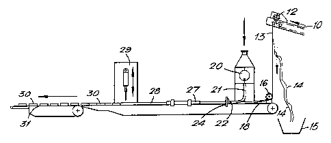
Figure 1
represents a side plan view of a machine according to the
invention
Figure 2
represents a top plan view of the machine of Figure 1.
Iv ~ X388
6
Figure 3
represents a side plan view of part of the machine
according to Figure 1 showing more detail,
Figure 4
represents a sectional view along the line B-B in Figure 3
ZO looking in the direction of the arrows,
Figure 5
represents a sectional view along the line C-C in Figure 3
looking in the direction of the arrows,
Figure- 6
represents a side view of a forming ring and filling
nozzle, and
Figure 7
represents a sectional view along the line A-A in Figure 6
looking in the direction of the arrows.
Referring to the drawings, the machine comprises a cooling
conveyor 10 transporting a blanched, cooled pasta strand
11, having a width of 30 cm.
Positioned above the cooling conveyor 10 at its downstream
end are four rotating circular knives 12 for cutting the
pasta strand 11 longitudinally into three central strips 13
and two scrap strips 14 one from each edge of the strand 11
which fall into a container 15.
' ~-~~1~8~
Three convex preforming rollers 16, around which the
central strips 13 may be trained to form curved strips 17,
are positioned above the upstream end of a cannelloni-
forming conveyor belt 18. The preforming rollers 16 are
rovided with side
p guides 19. Downstream of the preforming
rollers 16 is a filling pump 20 fitted with three filling
nozzles 21 each having an opening 22 containing filling 23
and downstream of the filling nozzles are three forming
rings 24 for forming closed tubes 25 each having an overlap
seam 26 from the curved strips 17.
A pair of ploughs 27 is provided for guiding the three
closed<tubes 25 into contact with each other to form a
continuous cannelloni strip 28 above which is a guillotine
cutter 29 for cutting the strip 28 into individual
cannelloni pieces 30. Beyond the downstream end of the
conveyor belt 18 is an acceleration belt 31.
In operation, the blanched, cooled pasta strand 11 is cut
longitudinally by the knives 12 into three central strips
13 from which the cannelloni is made and two scrap strips
14 from the edges which fall into the container 15. The
pasta strips 13 are trained around the convex preforming
rollers 16 which cause the longitudinal edges of the strips
to bend to form curved strips 17 which are transported on
the cannelloni-forming conveyor belt 18 to the filling pump
20. Each filling nozzle 21 is bent so that the end part
lies parallel to the conveyor belt partially surrounded by
the sides of the curved strips 17. The opening 22 of each
filling nozzle is positioned just upstream of each final
forming ring 24 and the curved strips 17 are raised above
the conveyor belt 18 as they are transported to pass
through the forming rings where they are formed into closed
tubes 25 while simultaneously the filling 23 is deposited
into the curved strips 17 from the openings 22 of the
filling nozzles 21 to form three closed tubes 25 each with
~.~~ ~~~(~~
8
an overlap seam 26 having a width half the diameter of the
cannelloni and containing filling 23.
The closed tubes are transported past the ploughs 27 where
the are
y guided to contact one another and form a
continuous cannelloni strip 28 which is then cut by the
guillotine cutter 29 into individual cannelloni pieces 30.
The cannelloni pieces 30 are then transferred from the
downstream end of the conveyor belt 18 onto an accelerator
belt 31 which separates the pieces 30 from. one another for
further processing.
The whflle process is electronically controlled by a
computer.
20