Sélection de la langue

Search

Sommaire du brevet 2128392 

Énoncé de désistement de responsabilité concernant l'information provenant de tiers

Une partie des informations de ce site Web a été fournie par des sources externes. Le gouvernement du Canada n'assume aucune responsabilité concernant la précision, l'actualité ou la fiabilité des informations fournies par les sources externes. Les utilisateurs qui désirent employer cette information devraient consulter directement la source des informations. Le contenu fourni par les sources externes n'est pas assujetti aux exigences sur les langues officielles, la protection des renseignements personnels et l'accessibilité.

Disponibilité de l'Abrégé et des Revendications

L'apparition de différences dans le texte et l'image des Revendications et de l'Abrégé dépend du moment auquel le document est publié. Les textes des Revendications et de l'Abrégé sont affichés :

  • lorsque la demande peut être examinée par le public;
  • lorsque le brevet est émis (délivrance).
(12) Demande de brevet: (11) CA 2128392
(54) Titre français: RACCORD POUR CONDUIT ELECTRIQUE MUNI D'UNE MISE A LA TERRE INTEGREE
(54) Titre anglais: ELECTRICAL PIPE FITTING WITH INTEGRAL GROUNDING FIXTURE
Statut: Réputée abandonnée et au-delà du délai pour le rétablissement - en attente de la réponse à l’avis de communication rejetée
Données bibliographiques
(51) Classification internationale des brevets (CIB):
  • H02G 3/06 (2006.01)
(72) Inventeurs :
  • LUU, LU VINH (Hong Kong, Chine)
(73) Titulaires :
  • PACOMEX CO. LTD.
(71) Demandeurs :
  • PACOMEX CO. LTD. (Hong Kong, Chine)
(74) Agent: MCCARTHY TETRAULT LLP
(74) Co-agent:
(45) Délivré:
(22) Date de dépôt: 1994-07-19
(41) Mise à la disponibilité du public: 1995-01-22
Requête d'examen: 2001-06-28
Licence disponible: S.O.
Cédé au domaine public: S.O.
(25) Langue des documents déposés: Anglais

Traité de coopération en matière de brevets (PCT): Non

(30) Données de priorité de la demande:
Numéro de la demande Pays / territoire Date
08/094,213 (Etats-Unis d'Amérique) 1993-07-21
08/270,211 (Etats-Unis d'Amérique) 1994-07-07

Abrégés

Abrégé anglais


ELECTRICAL PIPE FITTING WITH INTEGRAL GROUNDING FIXTURE
ABSTRACT OF THE DISCLOSURE
An electrical pipe fitting with integral grounding
fixture for securing a grounding wire. Each electrical pipe
fitting includes a hollow metal tubular member for receiving
electrical wire. The tubular member is adapted to be coupled as
an intermediate section of a grounded electrical pipe. The
tubular member has a first end and a second end. The first end
is adapted to be coupled to a section of the electrical pipe.
The second end includes threads which mate with threads on a
collar to secure the fitting to the receptacle box. A raised
portion extends from the tubular member and includes an aperture
for receiving and securing a grounding wire, whereby a ground
path is established between the grounding wire and the electrical
pipe. The raised portion can be formed integrally with the
tubular member or provided on a separate sleeve which extends
over the tubular member. The electrical pipe fitting can be
either a straight section, or alternatively, can include an
angled corner. A removable cover is provided to cover the
opening formed by the angled corner to allow access to the
electrical wire. A frictional lock is provided to prevent
unintentional dislodging of the cover.

Revendications

Note : Les revendications sont présentées dans la langue officielle dans laquelle elles ont été soumises.


- 9 -
WE CLAIM:
1. An electrical pipe fitting, comprising:
a hollow metal tubular member for receiving
electrical wire, said hollow tubular member adapted to be
coupled as an intermediate section of a grounded
electrical pipe; and
a raised portion formed integrally with and
extending from said hollow tubular member, said raised
portion having an aperture therethrough for receiving and
securing a grounding wire, whereby a ground path is
established between said grounding wire and said
electrical pipe.
2. An electrical pipe fitting as recited in
claim 1, wherein said hollow tubular member has a first
end and a second end, the first end having ridges adapted
to secure a section of said electrical pipe received over
said first end, the second end being provided with
external threads.
3. An electrical pipe fitting as recited in
claim 1, further comprising a screw which extends into
said aperture of said raised portion and presses an
uninsulated portion of said grounding wire against a wall
of said aperture.
4. An electrical pipe fitting as recited in
claim 3, further comprising a clamp disposed adjacent

- 10 -
said aperture of said raised portion for securing an
insulated portion of said grounding wire against hollow
tubular member.
5. An electrical pipe fitting as recited in
claim 1, wherein said hollow tubular member includes an
angled corner, such that said first and second ends are
perpendicular to each other.
6. An electrical pipe fitting as recited in
claim 5, further comprising a removable cover on said
angled corner.
7. An electrical pipe fitting as recited in
claim 6, wherein locking means is provided to prevent
unintentional displacement of said removable cover.
8. An electrical pipe fitting, comprising:
a hollow metal tubular member for receiving
electrical wire, said tubular member having a first end
and a second end, said tubular member being adapted to be
coupled to a grounded electrical pipe at said first end,
said tubular member also being adapted to be removably
connected to an electrical receptacle box at said second
end;
means for attaching a section of the electrical
pipe to the fitting;
means for securing the fitting to the
receptacle box;

- 11 -
a raised portion extending from said tubular
member, said raised portion having an aperture for
receiving and securing a grounding wire, whereby a ground
path is established between the grounding wire and the
electrical pipe; and
means for securing the grounding wire within
the aperture of said raised portion.
9. The electrical pipe fitting as recited in
claim 8, wherein said means for securing the grounding
wire comprises a screw which extends into said aperture
of said raised portion and presses an uninsulated portion
of the grounding wire against said hollow tubular member.
10. The electrical pipe fitting as recited in
claim 9, wherein said means for securing the grounding
wire further comprises a clamp disposed adjacent said
aperture for securing the uninsulated portion of the
grounding wire.
11. The electrical pipe fitting as recited in
claim 8, wherein the raised portion is formed integrally
with said tubular member.
12. The electrical pipe fitting as recited in
claim 8, further comprising a sleeve, said tubular member
extending through the sleeve, and said raised portion
being formed integrally with and extending from said
sleeve.

- 12 -
13. The electrical pipe fitting as recited in
claim 8, wherein said tubular member includes an angled
corner, such that said first and second ends are
perpendicular to each other.
14. The electrical pipe fitting as recited in
claim 13, further comprising a removable cover disposed
on said angled corner.
15. The electrical pipe fitting assembly as
recited in claim 14, further comprising locking means for
preventing unintentional displacement of said removable
cover from said angled corner.
16. The electrical pipe fitting as recited in
claim 8, wherein the section of electrical pipe is
received over said first end and said means for attaching
the section of electrical pipe comprises a plurality of
ridges on said first end of said tubular member.
17. The electrical pipe fitting as recited in
claim 8, wherein the section of electrical pipe is
received within said first end and said means for
attaching the section of electrical pipe comprises an
aperture in the first end of said tubular member and a
screw extending through the aperture to secure the
section within the first end.

Description

Note : Les descriptions sont présentées dans la langue officielle dans laquelle elles ont été soumises.

212~9~
ELECTRICAL PIPE FITTING WITH INTEGRAL GROUNDING FIXTURE
The present invention relates to an electrical
pipe fitting and, more particularly, to an electrical
pipe fitting with an integral fixture for securing a
grounding wire such as a bonding jumper.
Electrical pipe is often used for routing ~ :
electrical wires in commercial and residential
installations. In order to meet present day municipal
code requirements, the electrical pipe must be grounded, .
and fixtures must be provided to electrically connect
grounding wires to the ground~ed electrical pipe. ~-
As shown in Fig. 1, the typical solution is
to provide a clamp-on fixture consisting of a base 2 and
~ a U-shaped pipe clamp bracket 4 which are secured around :~ ;
: a pipe using screws 6~and 8.: A portion 10 of the base 2 :~
: receives a grounding wire 11 which is held in grounded :~
: : 20 ~ ~onnection with the~base by screw 12. A section 14 of
the~base~may be used to secure a wire clamping bracket 16
ovçr the;grounding wire;:~11 using screws 18 and 20.
: The~clamp-on fixture illustrated in Fig. 1
`su~fers from se~eral setbacks, including: (l) the ground -~.
25~ connection is subject~to failure,~or example, if the
clamp-on fixture~should:become loose; (2) the fixture
adds e~pense and~physical~bulk to any given installation,
: reguiring separate pieces of hardware which must ~e
purchased, kept~in stock and secured around the pipe or
.
~ ~ '

23L28~9Z ~ ~
- 2 - ;
connector; (3) the clamp-on fixture adds to the time
involved and increases the chance of error during the
installation, involving several steps in order to secure
and apply the grounding connection; and (4) the clamp may
cause the electrical pipe, or conduit, to crimp.
Although U.S. Patent No. 4,106, B32 to Burns - :-
discloses an electrical qround fixture including a pipe
section with ~n integral clamp, it is designed to
electrically couple a grounding wire to a grounded water
pipe sy-item of a building. Significantly, the fixture of
the Burns patent is not designed to provide a grounding -
connection for an elertrical pipe system to meet today's
building and electrical codes.
: .
The present invention improves upon the prior ~ ~
art by providing an electrical pipe fitting having an ~ -
integral grounding fixture which is specifically designed
to be used in an electrical conduit system to bring such
a system into compliance with municipal code
requirements.
The electrical pipe! fitting of the present ;
invention includes a hollow metal tubular member for
receiving electrical wire, the hollow tubular member
- being specifically~designed to be coupled as an
intermediate section of a qrounded electrical pipe. In
; this connection, one end of the hollow tubular member has
ridges for securing a section of electrical pipe and a
second end with external threadsO The tubular member is
: : ~' ~'.
:: : ~ ,
..: . -~ .

2~2~3~
-- 3
adapted to be removably connected to an electrical
receptacle box at the second end.
A raised portion extends from the hollow
tubular member and has an aperture for receiving and
securing a grounding wire.
Preferably, a screw is used to secure the
grounding wire within the aperture. The screw extends
into the iaperture of the raised portion of the fitting
and presses an uninsulated portion of the grsund wire
against a wall of the aperture to establish a ground path
between the grounding wire and the electrical pipe.
Additionally, a clamp is preferably disposed adjacent the
aperture for securing an insulated portion of the ground
wire against the hollow tubular member.
The raised portion can be formed integral with
the tubular member or integral with a sleeve which
extends over the tubular member.
The electrical pipe ~itting can either be a
straight section or, alternatively, can include an angled
corner, such that the ends of the fitting are
perpendicular to each other. A removable cover is
preferably provided in the embodiment of the invention
with the angled corner to facilitate access to the
electrical wire. A frictional lock is provided to
prevent unintentional dislodging of the removable cover.
Advantageously, the fixture of the present
invention is simple, economical, easily installed and
provides secure grounding at the point of connection.
" ': :''
.
9~

Z~28392
- 4 -
Other features and advantages of the present
invention will become apparent from the following
description of the invention which refers to the
accompanying drawings.
Fig. 1 illustrates a known clamp-on type
grounding fixture.
Fig. 2 is a first embodiment of the electrical
pipe fitting of the present invention having an integral
grounding fixture.
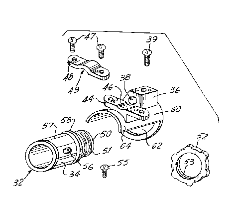
Fig. 3 is a second embodiment of the electrical
pipe fitti~g having a sleeve with an integral grounding ~ ;~
fixture.
Fig. 4 is another embodiment of the electrical
pipe fitting of the present invention having an integral
grounding fixture. ~ ;
Fig. 5 is a fourth embodiment of the pipe
fitting having an angled corner.
Fig. 6 is a back view of the pipe fitting of
Fig. 5.
Fig. 7 illustrates a slidable cover used over
the angled corn~r of the fitting of Fig. 5.
Fig. 8 is a perspective view o~ an electrical
; ~ ~ receptacle box with the removable elsctrical pipe fitting
2~ of Fig. 2~
Fig. 9 illustrates a receptacle box with the
electrical pipe fitting of Fig. 3.
:: :
. .
.:. . ~
. .
: '
::

~ 2~2839~
- 5 -
Fig. 10 illustrates the receptacle box with the
electrical pipe fitting of Fig. 4.
Fig. 11 is a perspective view of a receptacle
box with the pipe fitting of Fig. 5.
::
Referring to Fig. 2, the present invention
relates to an electrical pipe fitting in the form o~ a
hollow tubular member 34 for receiving electrical wire.
A raised portion 36 extending from tubular
member 34 has an aperture 38 for receiving a grounding
wire. A screw 39 extends into the aperture and presses
an uninsulated portion of a grounding wire against a wall
of aperture 38.
The hollow tubular member 34 is adapted to be
coupled as an intermediate section of a grounded
electrical pipe. Tubular member 34 has a first end 40
which fits snugly inside the end of a pisce of electrical
pipe or conduit. A number of small ridges 41 extend at
least partially circum~erentially around the end 40 to
assist in securing the end inside the conduit. When the
end 40 is inserted fully, the conduit end comes to rest
against a collar 42 on the tubular member 34. The collar
42 has raised bumps 43 which~afford a better grip on
tubular member 34.
A plat~orm 44 disposed adjacent raised portion ~ -
36 extends laterally with respect to the tubular member
and includes a U-shaped~recess 46 for receiving the
grounding wire. A wire clamp bracket 48 with an opposing
. -

2~ ~8392
-
- 6 -
U-shaped recess 44 is secured onto platform 44 with
screws 47, the wire being held in place between recesses
46 and 49. ~ -~
The tubular member 34 is also adapted to be ;
removably connected to an electrical receptacle bsx. As ~ -
shown in Fig. 8, a second end 50 of tubular member 34 can :~
be inserted through an opening 29 in the receptacle box : :
25. The receptacle box 25 has a plurality of removable
disc-shaped covers 26, each of which can be easily
punched out to provide an aperture for receiving the
second end 50 of tubular member 34. The second end 50 of :. :
tubular member 34 includes threads 51 which mate with ~ - -
threads 53 of a collar 52 to secure the fitting within
the receptacle box. The electrical receptacle box also
includes threaded tabs 27 for securing a face plate, and
apertures 28 for receiving screws to secure the :
receptacle box within a wall or other desired structure.
A second embodiment of the invention is shown
in Figs. 3 and 9, wherein like reference numerals are
used to d~signate like elements in Figs. 2 and 8. In the - :
second embodiment, the raised portion 36 and platform 44
are disposed on a separate metal sleeve 60, a portion of : :~
which, identified by reference number 64, extends over --
tubular member 34. Sleeve 60 has a hollow collar
:portion, perpendicular to portion 64, through which the
second end 50 of tubular member 34 is inserted, prior to
being inserted within the receptacle box. Thus, when
~: tubular member 34 is secured to the receptacle box by - ~.
tightening ~hreaded collar 53 onto the threads 51 of the .~.~
1;~` '' i I ' ', :
::: .
., ,. .:.
'' ;,~,
~";

~ ~8392
- 7 -
second end 50 of tubular member 34, sleeve 60 is secured
against the receptacle box by a raised circumferential
ridge 58 on tubular member 34.
The second embodiment of the invention shown in
Figs. 3 and 9 also differs from the first embodiment in
that electrical pipe fitting 32 comprises a straight
tubular member 34 for accommodating electrical wire, but
does not include a male end 40 extending therefrom which
fits into another section of electrical pipe. Rather,
tubular member 34 is a female piece and receives a
section of electrical pipe. A screw 55 extends through
an aperture 56 in tubular member 34 for securing the
fitting to the section of electrical pipe inserted
therein. Tubular member 34 includes ridges 57 spaced ~
axially around its periphery to facilitate gripping of ~ -
the fixture.
A third embodiment shown in Figs. 4 and 10 is
similar to the embodiment of Figs. 3 and 9, except that
raised portion 36 and platform 44 are formed integral `
with tubular member 34, rather than on a separate sIeeve.
A fourth embodiment of the invention, shown in
Figs. 5-7 and llo is similar to the embo~iment of Fig. 2,
with the exception that tubular memher 34 is formed with
an angled corner 66 which accommodates various installa-
tion configurations.
A removable cover 68 is provided to facilitate ~ -
installation and threading of electriaal wires through
the angled corner of the fitting. Removable cover 68
.. .
:'' ' ~'
' "' "

2~ 339Z ~-
-` . .
- B -
fits over an opening 67 in the angled corner 66, as shown
in Fig. 6. ~ :
Referring to Figs. ~ and 7, a locking mechanism
is provided to removably secure the cover 68 onto angled
S corner 66. As shown in Fig. 6, tracks 70 are provided on . :~.
opposite sides of opening 67. The tracks are equipped
with stops 72. As shown in Fig. 7, hooked projections 74 : :
are provided on opposite edges extsnding from the inner
surface 69 of cover 68. Removable co~er 68 also includes .
a small ramp 76 at one end disposed midway between hooked
projections 74. To install cover 68, hooked projections .
74 are slidably engaged over tracks 70, and the cover 68
is slid forward until projections 74 come to rest against
stops 72, at which point the removable cover fully
occludes the opening. Inadvertent opening of cover 68 is
impeded by ramp 76 which frictionally engages an edge of
the opening.
Although ths present invention has been `~
described in relation to par1:icular embodiments thereof,
many other variations and modifications and other uses
will become apparent to those skilled in the art. It i5 ~ ::
preferred, therefore, that the present invention be .
limited not by the specific disclosure herein, but only
: by the appended claims. .
:: :
~: :
~: ::

Dessin représentatif
Une figure unique qui représente un dessin illustrant l'invention.
États administratifs

2024-08-01 : Dans le cadre de la transition vers les Brevets de nouvelle génération (BNG), la base de données sur les brevets canadiens (BDBC) contient désormais un Historique d'événement plus détaillé, qui reproduit le Journal des événements de notre nouvelle solution interne.

Veuillez noter que les événements débutant par « Inactive : » se réfèrent à des événements qui ne sont plus utilisés dans notre nouvelle solution interne.

Pour une meilleure compréhension de l'état de la demande ou brevet qui figure sur cette page, la rubrique Mise en garde , et les descriptions de Brevet , Historique d'événement , Taxes périodiques et Historique des paiements devraient être consultées.

Historique d'événement

Description Date
Le délai pour l'annulation est expiré 2004-07-19
Demande non rétablie avant l'échéance 2004-07-19
Réputée abandonnée - omission de répondre à un avis sur les taxes pour le maintien en état 2003-07-21
Modification reçue - modification volontaire 2001-09-05
Lettre envoyée 2001-07-31
Inactive : Dem. traitée sur TS dès date d'ent. journal 2001-07-31
Inactive : Renseign. sur l'état - Complets dès date d'ent. journ. 2001-07-31
Exigences pour une requête d'examen - jugée conforme 2001-06-28
Toutes les exigences pour l'examen - jugée conforme 2001-06-28
Demande publiée (accessible au public) 1995-01-22

Historique d'abandonnement

Date d'abandonnement Raison Date de rétablissement
2003-07-21

Taxes périodiques

Le dernier paiement a été reçu le 2002-07-03

Avis : Si le paiement en totalité n'a pas été reçu au plus tard à la date indiquée, une taxe supplémentaire peut être imposée, soit une des taxes suivantes :

  • taxe de rétablissement ;
  • taxe pour paiement en souffrance ; ou
  • taxe additionnelle pour le renversement d'une péremption réputée.

Veuillez vous référer à la page web des taxes sur les brevets de l'OPIC pour voir tous les montants actuels des taxes.

Historique des taxes

Type de taxes Anniversaire Échéance Date payée
TM (demande, 3e anniv.) - petite 03 1997-07-21 1997-07-17
TM (demande, 4e anniv.) - petite 04 1998-07-20 1998-07-08
TM (demande, 5e anniv.) - petite 05 1999-07-19 1999-07-07
TM (demande, 6e anniv.) - petite 06 2000-07-19 2000-07-18
TM (demande, 7e anniv.) - petite 07 2001-07-19 2001-06-28
Requête d'examen - petite 2001-06-28
TM (demande, 8e anniv.) - petite 08 2002-07-19 2002-07-03
Titulaires au dossier

Les titulaires actuels et antérieures au dossier sont affichés en ordre alphabétique.

Titulaires actuels au dossier
PACOMEX CO. LTD.
Titulaires antérieures au dossier
LU VINH LUU
Les propriétaires antérieurs qui ne figurent pas dans la liste des « Propriétaires au dossier » apparaîtront dans d'autres documents au dossier.
Documents

Pour visionner les fichiers sélectionnés, entrer le code reCAPTCHA :


Pour visualiser une image, cliquer sur un lien dans la colonne description du document. Pour télécharger l'image (les images), cliquer l'une ou plusieurs cases à cocher dans la première colonne et ensuite cliquer sur le bouton "Télécharger sélection en format PDF (archive Zip)" ou le bouton "Télécharger sélection (en un fichier PDF fusionné)".

Liste des documents de brevet publiés et non publiés sur la BDBC .

Si vous avez des difficultés à accéder au contenu, veuillez communiquer avec le Centre de services à la clientèle au 1-866-997-1936, ou envoyer un courriel au Centre de service à la clientèle de l'OPIC.


Description du
Document 
Date
(aaaa-mm-jj) 
Nombre de pages   Taille de l'image (Ko) 
Dessin représentatif 1999-10-21 1 19
Dessins 2001-08-08 8 260
Page couverture 1995-04-08 1 121
Abrégé 1995-04-08 1 60
Dessins 1995-04-08 8 642
Revendications 1995-04-08 4 294
Description 1995-04-08 8 604
Rappel - requête d'examen 2001-03-20 1 118
Accusé de réception de la requête d'examen 2001-07-31 1 179
Courtoisie - Lettre d'abandon (taxe de maintien en état) 2003-08-18 1 176
Correspondance 1994-10-24 9 261
Taxes 1998-07-08 1 36
Taxes 2001-06-28 1 36
Taxes 2002-07-03 1 40
Taxes 1997-07-17 1 43
Taxes 1999-07-07 1 37
Taxes 2000-07-18 1 35
Taxes 1996-06-20 1 50