Note : Les descriptions sont présentées dans la langue officielle dans laquelle elles ont été soumises.
'~'0 94/08193 2 1 2 9 0 0 6 PC~r/US93/08977
~ --1--
METHOD AND APPARATUS FOR UPGRADING CARBONACEOUS FUEL
BACKGROUND OF THE INVENTION
The presenl invention is particularly applicable, but not necessarily restrictedto methods of processing c ~6OIlaceous materials under high pressures to increase
the BTU value of the carbonaceous material. Typical of the methods to which the
~ 5 presenl invention is applicable is the treating of various naturally occurring
ca,L onAceolJs ",aler;als, such as wood, peat or sub-bituminous coal, to render them
more suitable as solid fuel.
A number of invenlions relating to upgrading carbonaceous fuel have
herelofore been used or proposed so as to render the carbonaceous fuel more
suitable as a solid fuel. Many problems such as eAIensive costs, both in
manufacturing and operating carbonaceous fuel upgrading systems difficult and
complex cGnt, ols for enabling the operalion of carbonaceous fuel upgradillg systems
on a continuous basis, and a general lack of flexibility and versalilil~ of suchequipment for aclP~rt~;on for the processing of other ",alerials at cJirrere"l
temperatures and/or pressures are cG"""on.
The ",etl,ods and appafaluses of the p,esenl invention overcG"~e many of the
pr~tle."s and disad~anlages ~-~so~;~'ed with prior art equipment and techniques by
providing units which are of simple design, durable construction, ver~dlile in use and
readily ~dapl~ble for processing di~erenl feed ",alerials under varying temperatures
and/or pressures. The apparaluses of the plesen H nvention are further characterized
as being simple to control and e~ficianl in the utilization of heat energy, thereby
providing for econGmical operalion and a conservation of resources.
SUMMARY OF THE INVENTION
The ber,~6ts and advantages of the ~,resent invention are achieved by the
h ~w;ng Illelhocls and apparal-Jses in which carbonAGeous ",alerials are charged into
a heat exchanging apparat,Js cG,nprising at least one internal tube surrounded by an
outer casing under atmospheric conditions. After the carbonaceous material is
chaoged into the heat exchanging appa,dlus, the carbonaceous ,nalerial is injected
with a pressurized gas. In one embodiment of the present invention, a heat exchange
medium having a te""~e,dlure of between approAi,"dlely 250~F to about 1200~F andgenerally about 750~F is circulated throughout the casing such that the heat exchange
medium is in cGnla~1 with the outer periphery of the internal tube(s). The heat
eAchange medium enters the casing through a first valve located proAi,nale to the top
WO 94/08193 2 1 2 9 0 0 6 PCr/US93/089
- 2 -
of the heat e~cchanger and exits the casing through a second valve located proximate
to the bottom of the heat exchanger. The temperature remains elevated for a
co~ d period of time to effect an increase in the BTU value of the carbonaceous
")alerial. Water and other by-products such as tar and gases which have been
driven from the ca,l,Gnaceous ",alerial are recovered through a valve located at the
bottom of the heat exchanger. At the conclusion of the heat exchange step the
ca,l,on~ceous ",alerial is l,ansrer,ed to one or more containment vessels where the
ca,Lonaceous ",ale,ial is stored until it can be l,ansfer,ed to an extruder for
pEl'~ti~ing.
In a second embodiment carbonaceous material is charged into a heat
exchanger having at least one internal tube which is surrounded by an outer casing.
The outer casing is provided with four inleVoutlet valves through which the heatexchange medium enters and exits the casing. The first valve is located proximate to
the top of the heat exchanger the second valve is positioned below the first valve
approAi",alely one-third the length of the heat exchanger the third valve is positioned
belowthe second valve appro,~i",~t. ly two-thirds the length of the heat exchanger and
the fourth valve is located below the third valve proxi",ate to the bottom of the heat
exchanger. In this embodiment, the heat eAchange medium is introduced through the
first valve and is circulated down the heat exchanger within the outer casing until the
heat exchan~e medium reaches the second valve which is opened to allow the heat
e,~change medium to be circulated back through a furnace where it is reheated. Once
the heat exchange medium has been reheated it is recirculated back through the first
valve. After subs~,)lially all of the water has been driven down below the level of the
second valve the second valve is closed and the third valve is opened causing the
water to vaporize and condense on the coal contained below the level of the second
valve. This process of opening and closing valves is continued until substantially all
of the water has been driven down to the bottom of the heat exchanger where it is
~o"~tqd and drained off. Again it is cGnle,nplaled that the heat exchange mediumwill have a temperature of betvJeen about 250~F to about 12~F and a system
pressure of bctweon about 2 PSIG to about 3000 PSIG.
A third embodiment of the preser,l invention co""~rises an outer casing into
which the carbonaceous ,nalefial is charged for upgrading. The outer casing includes
a plurality of ho,i~olltally aligned tubes located within the casing which contain the
heat excha"ge medium. The heat exchange medium is circulated downward in
succession throughout the ho, i~ontally aligned tubes while an inert gas is in~e ~d into
~0 94/08193 2 12 9 0 ~ 6 Pcr/US93/08977
~_ - 3 -
the casing. The te-"pe,at-lre of the heat exchan5~e medium will be between about250~F to about 1 200~F and the pressure will be bet~scn about 2 PSIG and 3000 PSIG.
A fourth embodiment of the p~senl invention cG,nprises an outer casing into
which ca,l,ol,Aceous .. aterial is cha(ged for upgrading, and a plurality of vertically
aligned tubes extending down into the casing. A heat exchange medium is circulated
throughout the vertically aligned tubes and inert gas is in,e_ted into the outer casing
to facilitate upgrading of the ca,bonAceolJs .nalerial. Hereto, the temperature of the
heat exchange medium will be be~/ on about 250~F and 1200~F and the system
pressure will be betv,~eon about 2 PSIG to about 3000 PSIG.
BRIEF DESCRIPTION OF THE DRAWINGS
Additional benefits and advanlayes of the prese..l invention will become
appalenl from a reading of the desc.iption of the preferred embodiments taken inconjunction with the specific examples provided and the drawings, in which:
Figure 1 is a h. .- tional sch6llldtic view of a batch type heat exchanger-basedfuel upgrading system zr-anged in accordance with the principles of the prese"l
invention;
Figure 2 is a f~,n~tional sche..,atic view of a continuous type heat exchanger-
based fuel upgrading system a,.d.)ged in accordance with the principles of the
present invention;
Figure 3 is a side elevation view of a second heat exchanger embodiment
having a plurality of inlet/outlet valves al,anged in acco(dance with the principles of
the p(esenl invention; and
Figure 4 is a side elevation view of a third heat exchanger embodiment having
an outer casing which holds the ca.~naceolJs .-.alarial and a plurality of ho.i~o.,lally
aligned tubes contained within the outer casing through which heat exchange medium
is circulated in accoldance with the principles of the prese"l invention.
Figure 5 is a side elevation view of a fourth heat exchanger embodiment
having an outer casing which holds carbonaceous ,.,alerial and a plurality of vertically
aligned tubes which extend into the outer casing through which heat exchange
~ medium is circulated in accorciance with the principles of the presel ~t invention.
Figure 6 is a cross-se~tional viewtaken along lines 5-5 sho,r:ing the tubes usedto circulate a heat ex,:hanye medium.
WO 94/08193 PCT/US93/08~'7
2~L2900~ 4
DETAILED DESCRIPTION
The presen~ invention is applicable for upgrading carbonaceolJs ,I,alefials
including, but not limited to, ground coal, lignite and sub-bituminous coals of the type
broadly ranging beh~een wood, peat and bituminous coals which are found in the
deposit~ similar to higher grade coals. CarbGnACeOIJS materials as mined generally
contain from about 20% up to about 8096 moisture and can often be directly employed
without any preliminary l.t,db"ent other than granulating the ca,Lonaceous material
to the desired size. The particle size of the carbonaceous ",alerial in large part
determines the time necsssAry to u~yfade the carbonaceous ,nalefial to the desired
level. In general, the larger the particle the more time it takes to upgrade thec~rL.on~Geous fuel.
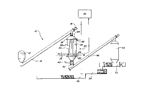
~th le~.rence to Figure 1, a batch type fuel upgrading system 10 is disclosed
as having a heat exchanger 20 which co,oprises a chamber having an inlet 24 at one
end and an outlet 26 at the other end, a plurality of tubes 28 extending the length of
the cha,nber and an outer casing 30 which surrounds the plurality of tubes 28.
Car~onAceous ",alt7rial is lldns~cGIlad from a bin 12 via conveyor 14 to the inlet end
24 Of the heat exchanger 20. Valves 16 and 18 located at the top of the heat
exchanger are opened to allow the carbon~Aceous r"alerial to be charged within tubes
28. A valve 41 provided near the bottom of the heat eAcl-anger 20 is closed prior to
filling the tubes 28 with c~,~onAceous ",aterial. After the tubes 28 have been filled,
the valves 16 and 18 are closed to contain the carbol-aceous ",alerial wHhin the tubes
28. An inert gas 34, such as nitrogen or another gas such as carbon dioxide, is then
inje~ted through valves 35 into the tubes 28 to fill the spaces bet~veen the
ca- l,onaceous pa, 'ic e s and raise the pressure wHhin the tubes. The nitrogen or other
inert gas is under pressure such that when the flow is activated the gas readily flows
into tubes 28 which are at at",ospheric pressure. When the pressure within the tubes
is raised to the desired level, the flow of gas is turned off.
A heat excl)ange medium, such as heated gas, moHen saH or prelerably an oil,
having a te" ,pe,ralure of bet~een about 250~F and 1200~F and pre~ra~ly about 750~F
jS continuously circulated throughout the casing 30 by e"lering the casing through
valve 46 and exiting valve 44. The heat excl~ange medium which exHs valve 44 is
passed through a furnace 36 which reheats it prior to roint,oductiQn of the medium
into casing 30. The inner wall of the casing 30 is provided with a plurality of
svccess;Je open-ended inwardly extending flanges 22 over which the heat eAcl-ange
medium flows in a step-like .. anner downward through casing 30. The inert gas or
wo 94/08193 PCr/US93/08977
'~ 212900~
- 5 -
carbon dioxide gas acts as a heat l,al,s~er carrier by coming into conlact with the
inner wall of the tubes 28 absorbing heat and driving the heat into the carL on~ceous
")alefial.
In the event that the ca, L on~ eous malerial contained within the tubes 28 has
a sulfur co,ltenl above a desired level, h~ ogen can be i" e ted into the tubes 28
along with the inert gas or carbon dioxide gas to drive e~cessive suHur out of the
ca,L.onaceous ",alerial. Generally, the amount of hyd~ogen needed is directly
propo,tional to the percentage of sulfur to be removed.
Moisture contained in the ca,L,onAceous n,dlerial is driven downward within the
tubes 28 as a result of the cJo~ d flow of the hot heat G,~change medium around
the tubes. At a sufficiently high temperature the moisture contained in the
c I lJonA~olJs ",dt~rial vapGri~es and condenses on the cooler carbol)aceous material
located toward the bottom of the tubes 28. Eventually, subsla"lially all of the water
along with other by-products such as tar and gases, is ~ ~1 e ted at the outlet 26 of the
1 5 heat exchanger 20. A valve 40 located at the bottom of the heat exchanyer 20 can
be opened to drain the water and other by-products from the heat exchanyer.
The amount of time the c~,l,GnAceous ",dlefial must remain within the tubes
28 will vary depending upon the size of the granules, the te"~peralure at which the
system is operated, the pressure of the gas injected into the tubes and the heating
value that is desired. Typically, the amount of time ranges from about 5 minutes to
about 30 minutes. The amount of time required generally decreases as the
t~",pef~ture and pressure in the heat exchanger increase. Conversely, the amountof time required incfdases when lower tel"p~ res and pressures are used.
The process utilizing system 10 can be carried out at temperatures ranging
from approAi",ately 250~F to 1200DF and at pressures ranging from approxi")dtely 2
to about 3000 PSIG. The most consisl~nt results for upgrading the car~,onaceous
".alerial tend to occur when the te""~erature at which the heat exchange medium
circulates throughout the system is allowed to reach on the order of about 750~F.
At the conclusion of the heat excl ,anging and upgrading step, the pressure is
(~13~ed by opening the control valve 41. The tubes 28 located within the outer
casing 30 are em~tied by opening valve 41 and then valve 42 lo~lçd at the bottomof the heat excl-anger. The c~rLonAceous r"al~rial is then t.ans~er,ed upon a
conveyor 48 to a secor~l bin 50 where it is tenlpofa,ily stored. Extending from the
bottom of the second bin 50 is an extruder 52 which pelletizes the ca,bon~ceous
",al6rial and ~ans~er~ it to a cooler 54. After the carl,on~ceous n,ale,ial has cooled
WO 94/08193 .; ~ PCr/US93/08977
2129006 6 -
sufficiently, the .,.al~rial is lransfe"ed to a second extruder 56 which l,ari~fers the
pellets to a alorage site.
With reference to Figure 2, a continuous type fuel upgrading system 21 0 is
shown. The continuous fuel upgrading system includes a pair of containment bins
212a and 212b, otl.erv~se ref~,rred to herein as lock hopper~ which store the
ca.L,G.)AceolJs ",alerial to be upy,aded. The carbonaceous ".alerial is cleposited on
a conveyor 214 which leads to the top of the heat exchanger 220. Bottom valve 241
is closed, then the carbonAceo-Js .,-al~lial is passed through a valve 218 provided at
the top of the heat eAcl)anger and into tubes 228 contained within outer casing 230.
The process is r~ndered continuous, since one of the lock hopper 21 2a or 21 2b can
be refilled while the other one is being emptied via conveyor 21 4.
Once the tubes 228 are full, the valve 21 8 is closed and an inert gas such as
nitrogen or anoU.er gas such as carbon dioxide is injected into the tubes 228 under
pressure. The inert gas 234 or other gas such as carbon dioxide is under pressure
such that when the flow is activated the gas readily flows into tubes 228 which are at
db.,ospheric pressure. When the pressure within the tubes is raised to the desired
level, the gas flow is turned off. The inert gas or other gas such as carbon dioxide
raises the pressure of the system to betvJeen about 2 PSIG to about 3000 PSIG, and
p,e~rably will raise the pressure of the system to about 800 PSIG. After the tubes
have been pressurized, the len,peralure of the carLGnAceous ",dle,ial is raised by
continuously circulating a heat exchange medium throughout the casing 230 as
desc,il~ed with f~ele.ence to heat eAcl)anger 20 in Figure 1. Again, becAuse of the
do~ d flow of the heat eAchange medium, substarltially all of the moisture
contained in the ca,l,onaceous ,nalerial is driven to the bottom of the heat exchanger
220, where it can be c o"~ct~d and drained off through valve 240 along with any by-
products such as tar or other gases, which are driven off. The heat exchange medium
exits the casing 230 via valve 239 and is circulated through a furnace 236 prior to
being r~int,~Juced through valve 238. It is conle",plaled that the temperature of the
heat eAchange medium will be l~tv:een about 250~F to about 1 200~F and preferably
will be about 750~F.
The r.it~en 234 or other inert gas serves as a heat l,ansler carrier by
cGnt~cting the inner wall of the tubes 228, picking off the heat and lransfer,ing it into
the carLonAceous n.~t~,.ial. Once the heat eAchanging and upgrading process is
completed, valves 241 and 242 are opened at the bottom of the heat exchanger 220allowing the pressure to be reduced to at nospl)eric pressure and the carbonAr,eous
WO 94/08193 2 1 2 y o ~ ~ Pcr/US93/08977
- 7 -
.,.alerial to drop onto a conveyor 248 which l-ansft,rs the malerial to a pair of output
lock hopper:i 250 and 252. A valve 254 is opened on the first lock hopper 250
allowing the ca.l.o,.aceous ...ale.ial to be deposiled therein. Once the first hopper
~ 250 is full, the valve 254 is closed and the valve 256 pos~ioned on the top of the
second lock hopper 252 is opened so that the c~l,on~eeo~ls .,.alerial can flow into
it. Both lock hoppe.s 250 and ~ are provided with extruders 258 and 260
resp6cti~ely, pelletize the ca.Lonaceous .-,ale,ial and which l.~ns~er~ it to a cooler
262. After suffici~nt cooling the c~l,onA-~ous mdl~lial is l-ansft7r,ed to a second
extruder 264 which l.anspGIt~ the carbon~ceous ll,alerial to a slorage facility.Figure 3 shows a second embodiment ot a heat eAchanger 1 20 which can be
used with the batch type system of Figure 1 in accor.Jance with the present invention.
In this embodiment the heat exchanger 120 includes an inlet 124 and outlet 126 for
the carL,on~ceous r ,a~3. ial located at opposi"g ends of exehanger 120, a plurality of
tubes 128 into which the c~bon?.ceous ",al~rial is charged for upgrading an upper
valve 118 and a lower valve 141 to maintain the ca,l,oo~reous "~ale,ial under
pressure within the tubes 1 28 and an outer c~ing 130 which surrounds the plurality
of tubes and inlet valves 1 35 for injecting an inert gas 1 34 or another gas such as
carbon dioxide into the tubes. The inert g~ or carbon dioxide g~ is under pressure
such that when the flow is activated the gas readily flows into tubes 1 28 which are at
atmospheric pressure. When the pressure within the tubes is raised to the desired
level the gas flow is tumed off. Generally, the inert gas will raise the pressure of the
system to t~etv:aen about 2 PSIG and 3000 PSIG and pre~erably to about 800 PSIG
The outer c~ing 130 includes four inleVoutlet valves 144147 through which heat
excl1ange medium is circulated. The first valve 144 is located proAi",ale to the top of
the heat exchanger just below the valve 118. The second valve 1 45 is located down
about one-third the length of the heat exchar,ger 120 below the first valve 1 44. The
third valve 146 is located down about two-thirds the length of the heat exchanger 120
below both the first and secor.d valves and the fourth valve 1 47 is located proxi" ,ale
to the bottom of the heat exchanger 120 above valve 141. Extending from the inner
wall of the casing 130 are a number of open-ended flanges 122 ar,anged in an
alter.,d~ing step-wise fashion overwhich the heat excl1al1ge medium flows downwardly
within casing 1 30.
After valve 1 41 has been dosed, the carl,ol1~ous .-,al~rial has been cl.arged
into the tubes 128 and the valve 118 has been closed and the inert gas or carbondioxide has been injected into the tubes 128 a heat exchange medium is continuously
2 1 2g 0 ~) g ~ Pcr/US93/08977
- 8 -
circulated throughout the casing 130 to increase the temperature of the carbonaceous."aterial contained within the tubes 128. The heat exchanye medium which has been
heated by a furnace 149 to a te..,perat.lre sutficient to vapo.i~e the moisture contained
within the ca,bonaceous r..dte.ial. Typically the heat exchange medium is heated to
' ehueen about 250~F and about 1200~F and is prefarably heated to about 75~F. The
heat exchange medium is introduGed into casing 130 through the first valve 144. With
valves 144 and 147 open and valves 145 and 146 closed initially, heat exchange
medium is allowed to fill the casing 130. Once the casing is filled, valve 147 is closed
and valve 145 is opened so that the heat exchange medium circulates mainly through
the upper one third of the casing. As the heat exchange medium flows to the end of
the uppermost flange 122, the heat exchange medium flows down to the next flange122. This back and forth d~ d flow continues until the heat exchange medium
,eacl)es the second valve 145 where it flows out through the second valve 145 and
is circulated back through the fumace 149 for reheating. During the process of
circulating a heat exchar.ye medium throughout the casing 130, moisture which iscontained in the ca.LonAceovs ...at~.ial vapG.i~es and condenses on the cooler
c~L Gn~ceous ,-,alerial located below the level of the heat excl1anger where the heat
e,.cl ,ange medium is being circulated. After suLslantially all of the moisture contained
in the ca-l,ol-Aceous ..-alerial located in the top one-third of the tubes 128 has been
driven down below the level of the second valve 145, the second valve 145 is closed
and the third valve 146 is opene.l while the fourth valve 147 remains closed. This now
allows the heat GAchanye medium to circulate throughout the top two-thirds of the
casing until essentially all of the moisture vapGri~es and condenses on the
carLGnaceolJs ..,alerial located below the level of the third valve 146~ When
sul.~lantially all the moisture is contained below the level of the third valve 146, the
third valve 146 is closed while the second valve 145 remains closed and the fourth
valve 147 is opened. Eventually, su~lantially all of the moisture which was ~.esenl
in the charge of ca.l,onAceous ...ale.ial is driven below the level of the fourth valve
147 where it is co"sc~ed and drained from the heat exchanger through valve 140
along with other by-products, such as tar and other gases, which come off the charge.
After the upgrading process is complete, the charge is fed to extruder 150 for
,~"Eti~ing.
Figure 4 shows a third embodiment ot a heat exchanger 320 which ,~re~erably
is used with the batch type sysbm of Figure 1 in accGrdal)ce with the presenl
invention. In this embodiment, the heat exchanger 320 includes an inlet 324 and an
~O 94/08193 2 1 2 9 o ~ ~ Pcr/US93/08977
g
outlet 326 located at opposit~ ends of the heat e~changer a plurality of horkonlally
aligned tubes 344(a-d) through which heat exchange medium is circulated to heat the
ca"Lonaceovs n,ate,ial and an outer casing into which the ca,bonaceous ma~erial is
- cl,aryed. The carLGnaoeou.s ."dt~rial is ~llopped onto one of two axially aligned
augers ~ which rotate outwardly to distribute the carLonAceolJs ",alefial throughout
the casing 330. Valve 336 is closed prior to charging the carbons.ceous material into
the outer casing 330. Once the ca",onAreo~s ~nale.ial has been charged into the
outer casing 330, valve 334 is also closed and an inert gas such as nit.Ggen 338 or
some other gas such as carbon dioxide is in e. 'ed into the casing 330. The inert gas
is under pressure such that when the flow is activated the gas readily flows into
casing 330 which are at at-..os~,he.ic pressure. When the pressure within the tubes
is raised to the desired level, the gas flow is turned off. It is desirable to raise the
pressure of the system to between about 2 PSIG and about 3000 PSIG with the
preferred pressure being about 800 PSIG. The outer casing 330 includes a plurality
of horiLonlally aligned tubes 344(a-d) having inleVoutlet valves 342(a-h) through which
heat exchar.ge medium is circulated. Initially the heat exchange medium enters the
hGriLo.ltally aligned tubes 344(a) through the first valve 342(a). The heat eAchange
medium travels through the first tube 344(a) until it .eacl)es the trailing end of the first
tube and passes through valve 342(b). At that point the heat exchange medium is
I.an;-~rl~d to a second ho-i~ontally aligned tube 344(b) via a coupling member 346.
The heat exchange medium enters the tubes 344(b) through valve 342(c) whereby the
direction of flow is oppos-ite that of the first hGriLGIllally aligned tube 344(a). This
".eU,od of circulating the heat excl.ange medium throughout the hGr;~OnlaIIY aligned
tubes 344(a-d) and valves 342(a-h) continues until the heat exchange medium exits
tubes 344(d). Once the heat eAchange medium passes out of tube 344(d) through
valve 342(h), the heat e~cl ,anye medium is passed through a furnace 360 where it is
fehedtad prior to being roi. Itroduced through the first inlet valve 342(a). Generally it
is necessary to heat the system to betv:~en about 250~F and about 1200~F and
preferably to about 750~F to vapo.i~e the moisture contained within the carl,onaceous
"~aterial. Again, this m~thod of circulating the heat e~change medium back and forth
in a ~ n;.a~d direction causes suL,starltially all of the moisture contained within the
carbonaceo-Js ...aterial to be driven out of the charge along with any other
by-products such as tar and other gases, where it is celle_ted off at valves 350located at the bottom of the heat exchanger. After the upgrading process has been
completed, a second pair of augers 340 ~ a.~sh3r the upgraded carLon~ceolJs ,.. alerial
. ~,TIUS 9 3 / o 8 9 i
~~3 Rec d p(~'T P f~ 2 9 ~UG t994
to the outlet 326. A blanket of insulation 352, shown partially cut away, is provided
around the periphery of the casing to assist in maintaining the heat exchange medium
at a relatively conslan~ temperature. Also provided along the outer casing 330 are a
plurality of hatches 346(a-d) which allow access to the tubes 344(a~) whenever
~iLhd.awe' of the tubes 344(a-d) is necessAry.
Figures 5 and 6 de,non~tldte a fourth embodiment of a heat exchanger 420
useful with the prese.,l invenlion. In this embodiment, the heat exchanger includes
an inlet 424 and an outlet 426 located at opposiie ends of the heat exchanger, a tube
428 for directing the carL,oneceous .-,al~riai down into the heat exc1)an~er, a plurality
of vertically aligned tubes 444 extending from a plate ma..~ber 440 which separates
the heat exch~-ge medium from the carl,on~oeous n.aterial and an outer casing 430
into which the ca.Lonaceous ~.,dteriai is ch&~3ec-i. To utilke the heat e~changer, valve
442 located proAin,~t~ to the outiet 426 is ciosed and the c~bon~ceous material is
deposited into the outer casin~ 430 through inlet 424, vaive 418 and inlet tube 428.
Valve 418 is then ciosed and an inert gas such as nitrogen or some other gas such
as carbon dioxide is in,e ted through an inlet 447 into the outer casing 430 to raise
the pressure of the system. Typically, this inert gas will raise the pressure of the
system to betwoen about 2 PSIG and about 3000 PSIG and pref~rably to about 800
PSIG. When the pressure inside the outer casing reaches the desired level the gas
flow is tumed off.
Heat e~;hL~e medium i8 continuously circulated throughout the vertically alignedtubes 444 to raise the le.l,perature ot the c~bonaceou~ ,nat~rial. To assist in the
circulaUon, preca99 sha~ts 456 extend ~nto each of the verticaiiy aiigned tubes 444.
As the heat 6xehan~er medium col l~,~ the shafts 456, the heat exchange medium
tends to swirl within the tubes 444 due to the turbulent flow. The heat exchangemedhJm enters the heat oxch er throu~h valve 446, travels up and down through
each of the vertically aligned tubes 444 into open area 448 and out vaive 450 where
it passes throu~h a hrnace 460, and reintroduco~ through vaive 446. Ideally, thetemperature of the heat exol~ange medium will be b~tween about 250~F and about
1200~ and preI~rabl~r will be about 750~F. The moisture and other by products such
as tar and other gases, are col'c ~ed at the outlet 454 prior to collecting the
cart,on~ceous Illaterial by opening valve 442.
To reduce the operating times under the embodiments ~ sclosed in Figures 1 ~, the
inert gas which is passed through the system can be p,ehealed to a ten,peral-lre~pproad~ing the optimai operational te",pe,atures of the heat eAchange medium.
AMENDED SHEEr
S ~ ~ / o 8 9 7 7
2 ~ n~ T~t~ ~ g ~UG ~ 4
Desirable reductions in the overall operalion time of the system have been obtained
~or example, when the inert gas ~ei"per~ture has been prehealed to approxi",ately
50 F below the te",,cerature of the heated carlJonA--eous ",alerial.
In the event that the carl,on~ceolJs ll.at6rial contains an undesi(ably high level
of sulfur the ca,LGn~oQow ",aterial can be treated either before or after the heat
exchange and upgrading step is carried out. Prior to upgrading the carLonaceous
fuel the amount of H2S that is generated duriny the up~rading process can be limited
to a desired amount by adding flne amounts of a wlL.6nt .nalerial such as limestone
to the charye of ca,~oneoeous ",aterial. Due to the te"~perature and pressure over
time the sGrb6rlt will adsorb most of the H2S ~enerated. This p(c~Y~ eliminates the
need for additiGnai costly equipment. The finished product can then be passed over
a vibrdting sueen which separales the wl l~nl m~terial from the upgraded
ca,i~onPoeous ,ndte,ial priortothe extrusion and pelletizing steps. Additionaliy before
the c&rl,Gne~ous Illal6rial is extruded and r9 ~t~i~e~ fresh sGrt~enl can be added on
a mai percent basis of sulfur to caidum ~uch that when the c~l,oneceous n,alerial
is bumed up to 96% of the S~x can be captured before K enters the atmosphere.
In order to further illustrate the ,cr~nt Invenffon, the f~ ~w;ny specific
examples are prof;ded. It will be ul~de~t~xl that the~e examples are provided asbeing illustrative of usable v~ in the time, te"-pe,ature and pressure
rel~tionships employed in the ~nvenffon and ue not ~nbnded to Umit the scope of the
invention as here~n Jes~iL~ and as set forth in the subjoining claims.
iExamDle 1
Wyoming wbbituminous coal having an as mined moisture conlsnl of 31.0~6
by weight and a ineating vaiue of 7,776 BTU per pound was charged into the
containment tubes ot the heat exc;l ~)~er o~ Fi~ure 1. The top vaive was then closed
off and nrtro~en was introduced ~nto the tubes eontain~ng the svbbituminous coal.
The pressure inside the tubes was maintained at aoo psig while the te"~per~t.lre of the
heat e~chan~a medlum wa~ maintained at 750DF. The te",peralure of the
ca, Lonaceous ,- .~terial contained within the tubes reached 66gF. The fuel upgrading
proeess was carried out for 20 minutes. At the eompletion of the upgrading process
a valve located at the bottom of the heat e~ er was opened and the charge was
removed. After the upgrading process was completed, the c~ ~ona~ous m aterial had
an i, ~cre~6J heaUng value of 12,834 BTU per pound on a moisture free basis.
AMR~DED ~HEEt
WO 94/081 93 PCI /US93/0897'
29006 -12 -
Example 2
North Dakota lignite having an as mined moisture conl~nl of 37.6g% by weight
and a heating value of 6,784 BTU per pound was charged into the containment tubes
of the heat excha"ger of Figure 1. The top valve was then closed off and nitrogen
was introducisd into the tubes containing the lignite. The pressure inside the tubes
was maintained at 900 psig while the temperature of the heat exchange medium wasmaintained at 750~F. The t6",p6ral.Jre of the ca,bonA~ceous ",alefial contained within
the tubes reached 656~F. Ths fuel upgrading process was carried out for 19 minutes.
At the completion of the upgrading process, a valve located at the bottom of the heat
eAcllan~~er was opened and the charge was removed. After the upgrading process
was completed, the ca, bonAceous .nalefial had an increased l)eali,-g value of 12 266
BTU per pound on a moisture free basis.
ExamPle 3
Canaclian peat having an as mined moisture cor,le,lt of 67.2% by weight and
a heating value of 2,854 BTU per pound was charged into the containment tubes ofthe heat exchanger of Figure 1. The top valve was then closed off and nitrogen was
introduced into the tubes containing the Canadian peat. The pressure inside the
tubes was maintained at 1,000 psig while the ~",pe,~t.lre of the heat eAchange
medium was maintained at 750~F. The te"~p~alLIre of the carbonaceous material
contained within the tubes reached 680~F. The fuel upgrading process was carriedout for 20 minutes. At the completion of the upgrading process, a valve located at the
bottom of the heat eAcl,anger was opened and the charge was removed. After the
upgrading process was completed, the c~L.on~ceolJs ",alerial had an increased
heating value of 13,535 BTU per pound on a moisture free basis.
E~cample 4
I larc;~:~ 2 d having an as mined moisture cGn~enl of 70.40% by weight and a
heating value of 2,421 BTU per pound was cl ,a(ged into the containment tubes of heat
exchanger of Figure 1. The top valve was then closed off and nitrogen was
introduced into the tubes containing the hardwood. The pressure inside the tubeswas maintained at 800 psig while the te",peralure of the heat eAchange medium was
maintained at 750~F. The ~""~eral.lre of the carbGn~ceous ",ale, ial contained within
the tubes reached 646~F. The fuel upgrading process was carried out for 7 minutes.
At the completion of the upgrading process, a valve located at the bottom of the heat
eAchangQr was Gpenecl and the charge was removed. After the upgrading process
~vo 94/08193 2 1 2 9 ~) o ~ ~ Pcr/usg3/08977
~ ,,
- 13 -
was completed, the ca,l.onereous ",ale,ial had an i,lcreased heating value of 11 414
BTU per pound on a moisture free basis.
The various embodiments of the present invention can also be utilized to
- ~ans~or,., relatively useless bio-mass materials into activated carbon which is useful
in making high purity charcoal. For example the bio-mass .. ,ale.ial is charged into
the containment tubes of the heat excl)ar,ger of Figure 1 while the tubes are
continuously swept with ~rehedled inert gas providing the system with a pressurewhich ranges from ~et~oen 2 PSIG to about 3000 PSIG depending on the actual
cG"~position of the bio-mass. The system temperature ranges from between about
250'F to about 1 500DF. In one test run (see Table 1 below) the containment tubes
were swept with Nitrogen flowing at 10 square fee per hour (SCFH) the average
t~l "per~iure was maintained at approAi, na~ely 750~F and the pressure was maintained
at appro,.i".~tely 20 PSIG.
nme SystemTemp. of Temp. of Pressur~ Pressure Nitrogen
(m~n) Temp. Tubes' Tubes' within Outside Flow
(~F) Outside Inside Tubes Tubes (SCFH)
Diameter Diameter (PSIG) (PSIG)
0 756 749 770 0 0 0
0:01 _ _ _ _ _ 10
1 :30 - 740 227 21.0 20.5 10
2:00 -- 740 188 20.1 19.5 10
3:00 741 743 169 20.0 19.4 10
4:00 749 753 159 20.1 19.5 10
5:00 757 763 156 19.9 19.2 10
6:00 761 769 160 19.9 19.3 10
7:00 760 771 181 20.1 19.5 10
8:00 760 771 252 20.1 19.5 10
9:00 758 768 442 20.0 19.4 10
10:00 758 766 599 19.9 19.2 10
11 :00 758 764 657 20.1 19.6 10
12:00 760 763 659 20.1 19.6 10
13:00 764 765 650 20.1 19.7 10
14:00 768 767 638 20.3 19.7 10
15:00 m 770 628 20.3 20.0 0
WO 94/08193 PCI /US93/08977
212900~
- 14 -
After 15 minutes within the heat e,.changer the Nitrogen sweep was discoutinued and
the bio-mass was sub~tarltially dried and cooled for approAi."al~ly 20 minutes. The
process l,a":.for..,ed the bio-mass r.,aterial into raw activated charcoal having a
hedting value of 12,949 btu on a moisture free basis.
While it will be appar~nl that the prefe.. ed embodiments of the invention
~Ji~closed are well calculated to fulfill the objects stated, it will be apprecialed that the
invention is susceptible to n,od;~;on ~,a.ialion and change without departing from
the spirit thereof.