Note : Les descriptions sont présentées dans la langue officielle dans laquelle elles ont été soumises.
wo g3~ls977 ' 2 1 2 ~ 3 ~ ~ PCT/~93J000~6
A tubular con~ainer provided at one end with a ftrst cap,
which has both a seallng ~unction and a plunger ~unction,
and at the oth~r end wlth a second cap with a spout.
The present invention relates to a container with a~ least one
closure means according to the preamble of claim 1.
The invention is particularly concerned with lubricant cartridges
and caps for sealing same.
Today, consciousness towards the en~ironment is greater than in the
past and containers must ~ulfill high safety demands, particularly
for substances which are detrimental to the environment.
Ne~ertheless, such containers should be simple and easy to produce
at l~w costs an~ their handling should also be easy and simple,
both as to filling, preferably fu~ly automatic sealing as well as
repeated ~ealing at great and m~intained safety, even after
repeated op~ning an~ closing operations. The closure means should
even be able to resist out~r and interior strain up to a certain
level, so that leakage may be avoided with comparatively great
secuxi~y. Furthermore, the contents of such a container must be fed
out in a simple and reliable way.
.
The previously known containers and their closure means do not
fulfill these demands, at least not in combination.
Caps which are pre~iously known in this ~echnical field, serve as
sealin~ means for a cartridge or the like between ~ts filling and
use. When using ~he: cartridge, the cap is normally remo~ed and
thrown away and has, therefore no further function to fulfill.
Beyond this limited function, previously known caps suf~ex often
from the drawback, that they do not seal the container sufficiently
safely. Leaksge may thus occur easily and fre~uently and of~en a
~ull contalner an~ maybe even adjacent containers, the contents of
which has leaked out, are thrown away, as it can be rather
unplea~ant to get hands, clothes etc polluted.
:,i
Apart from possible leakage, the previously known caps are never-
theless hard to remove, particularly caps which are not designed as
- ~ '
,.
.,
W093/15977 PCT/SE93/0~096
2 lC~ 9 3 ~
~crewcaps. If the caps are designed as screwcaps, i.a. increased
material thic~ness is required as well as extra means to provide
the cap with interior t~reads and furthermore extra means to
pro~ide khe one cartridge end with ou~er threads.
By US-A-4 934 570, there is previously known a cap for sealing one
end of a container for fast food in accordance wi~h the preamble of
present claim l. This cap is, in the middle of an nterior collar,
furnished with a circumferential incision, which is torn apart,
when a plunger is pushed against the cap bottomt whereupon said
bottom with app. half the axial length of the interiQr ~ollar
serves as plunger disk for ieeding out fast food. Such a design
shows drawbacks, as it may be very difficult and ~uite remarkable
forces may be needed to make the collar crack within the area of
th~ incision, where the collar continues ~n both sides in a
straight way with the incision at righ~ anyle in relation thex~to.
For this reason, as clear~y revealed by fig. 8, a need has occurred
to incre se su~stantially the ~hickness of the interior collar
above the incisiont in which way obviously the upp~r part of the
in~erior col~ar and the outer collar should be prsvented from
following ~he plunger disk, in case the incision does not crack in
spite of high pressure. Furthermorel this cap is not fixedly
secured a~ the container in any ~way and pressures arising within
the latter, e.g. when s~ueezlng the container, would immediately
ad to ~liding of the cap away from the container. E~en the
feeding out of ~he~con~en~s of the conta:iner has to be regarded
disadvantageous, ~s~ that part o~ the interior collar which forms
part the plunger~disk undergoes a change of shape from a posi~ion
of rest with a converging shape towards the contents of the
container to a paralleI positîon at applied plunger pressure,
whereby some of t~he contents of the container most probably will
en~er between the înkerior collar and the container wall thus
preventing a normal plunger function sr Ieaking out backward~ along
the free edge of the interîor co~lar~ Fi~ally, the remainder of the
interior collar and the outer collar left behind on the container
end are no~ secured in any way. These parts may be dislodged
unintentionally at any time and do thus constitute a waste problem.
WO93/15977 2 ~ 2 9 3 ~ ^~ PCr/SE93/0~6
Such a closure means may, to a limited extend, be tolerated for
harmless substances~ e~g. fast food. It is/ however, undoubtedly
unsuitable for substances which are detrimental to the environment,
as lubricants and the like.
One objective of the present invention is ther~fore to provide an
ad~antageous container with likewise advantageous closure means
which, avoiding or counteracting the above-mentioned draw~acks,
fulfill the above-mentioned demands in combination.
Another objective of ~he in~ention is to improve previously known
containers and their closure means in various respects,
particularly as to facilitating application of caps, guarantee ~he
applied position of the caps in spite of considerable outer and/or
interior strain, such as pressure, and to make possible a fast,
easy and simple removal of said caps when so desired.
Furthermore, there should be material sa~ing, and a fast, simple
and safe transition to a plunger function of the on~ cap without
damage on said cap ox other parts o~ ~he container, which should be
safeguarded. The cap par~ remaining in ce.rtain cases at the
container aft~r ~eparation of the plunger should be secured against
unin~ended r~lease. ~he ~ransi~ion of the cap from sealing to
plunger func~ion should be achievable in a simple way a~bitrarily
manuall~, e.g.~by tearing off an outer collar, or mechanically/
automatically by placing ~thç container in~o e.g. a pistol like
tool. There should be means for safe con~rol/ guiding~sealing of
the plunger and the line of fraction in the c~p with plunger
function shall permit r~latively easy desired separation and great
,
safety against undesired ~eparation. Furthermore, the choice of
this region should positively affect both separability and
subsequen~ guiding, con~rol and sealin~. Relevan~ parts of these
properties should also prevail at an optional cap sealing the other
container end and having solely sealing function and the container
as such should be designed to further such properties in a far-
reaching way, whereby e.g. tolerances, shrinking etc shall be
controlled.
,
WO93~15977 PCT/SE93/0~96
~9 ~
These objectives are achieved according to the invention by a
conkainer and at least one closure means, respectively, of the
initially described kind being shaped substan~ially as defined in
the characterizing clause of claim 1.
Further characteristics of and advantages with the invention are
revealed by the -following detailed specification with reference to
the accompanying drawings, which in a partly schematic way show
preferred embo~iments. In the drawings:
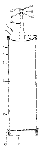
fig~ 1 is a diametrical axial sectional view sf a first embodiment
of a container according to the invention consisting of
circular cylindric tube and two caps sealing same,
fig. 2 is a par~ial diame~rical axial sectional view of a second
embodiment of a closuxe means according to the invention
similar to the one of fig. 1 but with 3 modified cap,
figs. 3 and 4 are partial diametrical axial sectional views of a
circular cylindrical ~ube according to the invention
s~aled at the one end by a cap similar to the one shown in
fig. ~ and at ~he other end by a ~hird ~mbodiment of a cap
according to the lnvention,
fig. 5 is a side elevational view of ~he container shown in fig. l,
: fig. 6 is a side elevatlonal view of the tube shown in figs. 1 and
5,
fig. 7 is a diame~rical axial sectional view of a tube shown in
'~ figs.1, 5 and 6, ~
fig. 8 is a: magnified sec~ional view of the one end profile of a
: tube according to fig. 7,
'~ fig. 9 is a side elevational view similar to the one of fiyA 5 Qf
a modified e~bodiment;
fig. lO is a diametrical axial sectional view of a container
~ according ~o fig, 9,
; flg. 11 is a side elevational view similar to the one of fig. 5 of
a further:modi~ied embodiment,
fig~ 12 is a diametrical axial sectional view of the container
according to fig. 11,
; fig. 13 is a magnified diametrical axial sectivnal view of a
. plunger C?p according to figs. 1, 4, 5 and 9 - 12,
., .
WO93J15977 212 9 3 ~1 ~ PC~/SE93/0~6
fig. 14 îs a magnified view of the upper part of fîg. 12,
figs. 15 - 18 show the plunger cap accordîn~ to fig. 13 in a
perspective view from above as well as a top plan vîew, a
side elevational view and an underneath plan view,
fig. 19 is a perspective view from above of a modified c~p simîlar
to the one of figs. 15 - 18,
figs. 20 - 22 show the cap according to fig. 14 seen from below,
from the slde and in a perspective vîew from above, and
figs. 23 - 26 show the spout cap of fig. lO seen from below, from
the side, from above and in a perspective fxom above.
A container according to the inventîon îs designated in its
entire~y by l. ~his container comprises a pre~erably circular
cylindric tube 2, which preferably îs made of plastic materîal ~y
înjection molding. ~Ae other part of the con~ainer~ which is
optional, is a cap 3, which is at Ieast partially matching in
shape. ~he ~ube is~prefera~ly made of polyethylene HD 7028 and the
cap of polyethylene~LD + HD.
~ ~ :
Characterizing for the tu~e 2 may be a flange 5, which p~eferably
surrounds;~the o~e ~tu~be end 4. :In accordance with~ a preferred
:embodimen~, this ~flange extends radially both inwardly and
outwardly from the respective~cylindrical sur~aces 7 and 8 of ~he
ube wall~6 to::form~an~interior flange 9 and an exterior flange 10.
;In accordance with~;a~preferxed embodiment, the in~erior flange 9
pro~e~ts longer rom;the~adjacent cylin~rical surface 7 ~han the
ou~er f~lange~ lO~:doe~:~from~its adjacent~surface 9. Typically, t~e
int~rior flange may~project 1~- 3 mm, preferably app. 2 m~,
wh~ile:the exterior flange may project 0.5 - 2.5 mm, prefera~ly app.
1 mm. Thi~s makes the:interior flange~creating a greater retaining
forc~e in:rela~ian~:to~the:cap 3 than the exterior flange. In ~his
way,:a cap at~ached to the tube may resist comp~ratively great
strain; particularly such strain which arises when the contents of
the:container is ~ub~ected to squeezing propagating a pressure on
the cap from the inside, e.g. when a ~ube falls down or is harshly
grasped. At ~he same time, it is nevertheless relatively easy to
,
. WO93/15977 PCT/SE93/0~96
,93~ 6
remove the cap e.g. ~emporarily, as for this the free exterior edge
of t~e cap outside the tube is grasped and heeled over and away
from tube end 4 with the radially shorter exterior flange offering
less resistance.
The int0rior flange 9 and the exterior flange l0 do suitably share
a common upper de}imitation surface ll forming the free axial end
surface of tube end 4.
In accordance wi~h a preferred embodiment, the interior flange 9 is
shorter in axial direc~ion than the exterior flange l0. Typically,
the interior flange can be 1 - 3, preferably approximately 2 mm
long, while the exterior flange can measure 2 - 4, pref~rably
approximately 2.~ mm in axial dir~ction, whereby an interior
~ealing surface 12 and an exterior sealing surface 14 are formed,
which preferably are situated within cylindrical, mutually coaxisl
~urfaces. While the exterior flange l0 is ~erminated at its axial
end which is turned away from surface l1 by a shoulder 15, which is
preferably situated within a radial plane, the intexior flange is
terminated within a corxesponding region preferably as an under-
cut surface 13, which may be straigh~ or concave ~o form a pointed
annular edge 18 J the purpose of which is to exert an extra sealing
e fec~ in r~lation t~ cap 3. The angle included between surfaces 12
and 13 amounts ~o:30 - 85, preferably; approximately 70. Even
another angle than 90 between surface~ l:l and 12 is conceivab~e,
nam~ly a larger angle ~han g0, ~.g. 90: - l30~ preferably app.
ll0~. It is also possible to provide at the outer par~ of surface
12 a bevel or curve to facilitate pu~hing o~ a cap onto the tube.
The cap 3 itself is~partially matching the shape of tube end 4 as
shown and described.:Accordingly~ the ~ap shows situated within a
radial plane, a ring part 16, which inwardly connects to a circular
cylindric ring part~ 17, which is closed by ~a bottom l9, which
preferably is slightly concave seen from outside. These three par~s
16, 17 and l9 ~how e.g. app. same material thickness, e~g. app. l
mm. Outwardly, ring part 16 connects to an outer circular cylindric
ring part 20, which is equally long as or somewhat longer in axial
~:
WO93/l5977 212 ~ 3 4 ~ PCT/SE93/0~6
direction than the interior ring part 17, measured from ring part
~6~
Parts 16, 17 and 20 define an annular groove 21 for receiving and
arresting tube end 4. To this purpose, parts 17 and 20 are provided
with circumferential shoulders, bulges or the like 24 and 28,
respectively, which are facing each other but are offset somewhat
in axial direction in relation to one another corresponding to the
previously described and shown difference in axial extension
between interior and exterior flange. With a cap firmly applied,
said shoulders, bulges or the like 24 and 28 are pro~ided directly
below surfaces 13 and 15, so that the cap may not be remo~ed
without considerable stretching away from tube end 4.
The free axial half 27 of ring part 20 may optionally be bent out-
wardly somewhat or provided:::with a circumfereQtial interior bevel
29 for facilitating pushing the cap onto the ~uhe end. For the same
purpose, that half of ring part 17, which connects to bottom 19,
may be provided with:a bevel 25.
As the outer: ring part~ 20 does not have to deYelop ~imilar resis-
tance~properties as to unintended rel~ase o~ the cap and the cap
`furthermore to a certain~ex~end should be removable inte~tionally,
this ring part is~:suitabl~:shaped somewhat thinn2r, e.g. 0.7 mm
thlck,~while the other~two:~parts and~even the ~ot~om may be shaped
app~ l mm thick:,: al~ in accordance with one non limiting
embodimen~
Beyond the effects~_describe~ hereinbefore, ~he closure means
accQrding to the~ invention is characteriæed by following
propertiesO Ih:~he normal s~aled position according to fig. 1,
excellent sealing is~achie~ed~around~the:entire periphery of both
inside, endside and outside of the tube. If so desired, ring groove
21 may be ~urnished ~with a sealing agent, e.g. silicon, in
connection with:the~filling and sealing of the tu~e at a factory~
In this way, ~extra great ~afety against leakage during ha~dling
:onward to the user is achieved.
WO93/15977 PCT/SE93/0~6
93 ~ 8
If a fill~d ~ube sealed by a cap as described and shown is exposed
to interior pressure for a reason as described before, such
pressure will affect primarily the cap bottom, which is pushed up-
wards to attain a more flat shape, whereby ring part 17 is pressed
against or ~owards the tube wall within the conne~ting region
between this part and ~he bottom and will inrease the sealing
pressure of the shoulder, bulg0 or the like 24 against and around
ring edge 18. Th~ pointed shap~ of the lat$~r guarantees in a far-
reaching way, that the cap may not be released at minor or medium
size pressures from the inside.
When applying pressure from the outside on e.g. ~he cap bottom in
axial direction, parts 16 and 20 and particularly the shoulder,
bulge or the lik~ 28 will resist such pressures to a practically
unlimi~ed extent. The shoulder, bulge or ~he like 28 functions here
as some kind of heeling stop, which preven~s in co~bination with
shoulder 15, that the peripheral channel part of the cap may
"glide" inwardly around tube end 4.
On the other hand, i~ i~ is desired to remove ~he cap, possibly
only temporarily, :this may be achieved comparati~ely simply and
easily by grasping from outside the cap part 27 at any place and
pulling and bending that place upwardly in fig. 2, so ~hat the
shoulder, bulge or t~e like 28 may pass ~eyon~ shoulder 15. This is
facllitated hy shaping ring part 20 somewhat thinner in combination
with manufacturing the cap in general of flexible plastic material
and/or of materlal which is less flexible per se but flexible due
to material thickness chosen. At continued pulling away of the cap,
the shoulder, bulge or the like 24 glides along and e~entually
b~yond ring edga 18, un*il the cap is entirely remo~ed.
If desired tv seal the tube again, the cap is attached loosely to
tube end 4 and is then pushed until the shoulder~ or bulges of the
cap have glided past the shoulders of the tube end, with elasti-
cally deforming the cap parts concerned and eventually have snapped
behind the tube shoulders or bulges and arrest the cap in this
position.
.
W093/15977 212 9 3 ~ ~. PCT/SE93/~96
As can be seen, the 0mbodiment accoxding ~o figs. 1 and 2 ~iffers
from the one shown in fig. 3 only in that the shoulders 2~. and 28
have been replaced by bulges and by shaping the bevels 25 and 29 in
a more reduced way.
Figs. 3 and 4 show an at least principally preferred embodiment of
a tube according to th~ invention pro~ided with two different
closure means, one at each end. The one cap and the one tube end
are suitably identically with or similar to the ~pper part of fig.
1 or fig. 2, while the other closure means differs there from and
is designa~ed in its entirety by 30. The latter me~ns comprises a
cap 31 having a preferably flat bottom 32 which substantially fills
the interior of the tube, and which centrally may be provided with
a circular recess 33 with a central protrusion 34 and a peripheral
annular groove 3~. Parts 33 - 35 are provided to be abutted by a
plunger rvd of e.g. a grease gun and/or may these parts be removed
by pushing away this central bo~tom par~ which/ however, remains
connected to the surrounding bottom part via a small radial bridge
63, which ia not shown in fig. 4 but in figs. 15 - 19. In the so
formed hole/ a spou~: of som~ kind, e.g. similar to the one shown in
fig. 1/ may be inser~ed.
.
The bot~om 32~ which is provided inserted into tube 2 i~ surrounded
by an lnterior collar 36, which reaches up to and somewhat beyond
the respective tube end 50 and is, at this ~nd, provided with an
annular groove 38, which cross-sectionally sui~ably is wedge-shaped
open1ng outwardly in~ pre~era~ly axial direction, and which is
provided in a bridge part 39 abutting said tube end 50 in a butt
way. Said bridge part connects~immediately ou~side of said tube end
to an exterior collar 40 abutting said tube end from the outside
and showing, app. in the middle of its ax~al extent, an annular
bulge 41 abutting said tube end and being provided to grasp around
and beyond an annular bulge 43 at ~his ~ube end, which latter bulge
in its turn forms an annular groove 51 on the in~ide of the tube,
into which interior groove the interior collar 36 is inserted with
a circumferen~ial~bulge 37. The free end part of the exterior
collar 40 may be bent somewhat outwardly and/or form an interisr
.
W093/15977 PCT/SE93/0~6
'l.~93~ lo
bevel 42 for facilitating pushing of the cap onto this tube end.
The latter cap is even a plunger to its func~ion, ~he exterior
collar 40 being pro~ided to be torn away or may ~he bottom with the
interior collar be sheared away without pxeceding tea~ing away of
the extexior collar, which i5 facilitated by the substantially
reduced thickness of the bottom of the annular groove 38 and in
that the bo~tom o~ the ~nnular groove is placed directly ayainst
the interior edge o~ the tube end concerned, which edge normally is
relatively sharp, and in that the bridge part 39 is placed butt
against said tube end, whereupon a plunger rod of a grease gun (not
shown~ may push the ~o formed plunger part of ~he cap longer in~o
the tube overcoming the r~taining foxce created by bulges and
grooves 37, 43 and 51, the retaining force of the bulge 41 of the
outer collar possibly having been eliminated before by tearing away
the outer collar.
With remained outer collar on the tube, the collar does partly not
have to be provided with a special ~earing means and is partly
secured in its position after separation from the interior collar
and the botto~ in that the bridge part even after separation will
abut the r~specti~e tube end from the one direction and the collar
bulge 41 will grasp around the tube bulge 43 from the opposite
direction. ~urthermore~ when separating the plunger c~nstituted by
bottom and in~erior collar with ~he outer collar remaining in
positlon, this wi11~render the advantage, ~ha~ the bulge 37 of the
interior collar will be retained in the in~erior groove of the
tube, until a certain pressure has developedO with which the
plunger rod ac~s upon_the cap bo~tom. Wh~n exceeding this pressure,
bulge 37 is released in a snap-like way out of groove 51!and the
actual pressure level will then have a sudden impact on the bottom
of the annular groove 38~and shear off the ~hin bo~tom agains~ the
underlying in~erior edge of the tube end. In this way, a high
threshold is achieved against unintended breakaway of this closure
means at the same time creating a desirably very limited region for
intended breaking up.
WO93/15977 212 9 3 4 1 PCT/SE93/~96
11
The spout 44 according to figs. 1, 5, 9, 10 and 23 - 26 may be an
outwardly conically converging pipe haYing an annular bulge 45 at
its free end, which bulge is intended to be surrounded by a small
cap 46 with a bot~om 47 and a sleeve wall 48, on the inside of
which there is an interior annular bulge 49. The spou~ is prefer-
ably integrated with the cap according to figs. 2, 3, 9, 10 or 23 -
26.
The cap 3 shown in figs. 2 and 3 by way of two different embodi-
ments is shown, in figs. 9 - 12, 14 and 20 - 26, in a third,
preferr~d embodiment. ~he ring part or flange 16 of cap 3 does
preferably not project radially bsyond tube flange 10 but
terminates somewha~ before reaching ~he latter s outer edge.
Figs. 21 and 24 reveal clearly, how the bulge 24 projects from the
lateral wall of the cap. B~yond the bulge, the cap begins two
incline obliquely inwardly for connecting to a bowl-like bottom 19.
Within the region for such a cap, tube 2 is either shaped to follow
the outside of the cap corresponding to the shape of tube end 50 or
is shaped as shown in figs. 10, 12 and 14. This shape prevent~ the
contents of the cartridge from being spilt and keeps the cap
securely fixed. The ~ttachment of the cap is facilitated and its
unin~ended removal i~ count~racted in ~ha~ the bulge downwardly
forms a longer ~evel with a minor angle, e.gO 30 - 45, in
relation to lateral wall 17, while the remainder upwardly is
xounded at a minor radius with an angle of e~g. 45 - 90 close to
the sidewall.
Fig. 22 shows the cap seen ~bliquely from above disclosing an
almos~ triangular gripping handle 52, which is intended to fac~
ta~e removal of the cap. The ~ripping handle i~ shaped in one piece
with the cap and i~ connected to a spok-like region uppermost at
sidewall 17 via a small ~ongue 53 forming a ~ran~ition in~o the
upper i~side of the flange of the cap. The wide upper flange
preYents the cap from being pushed into the tube. The cap is
preferably manufactured as one homogeneous piece, e.g. by injection
molding, preferably of PVC.
WO 93/15g77 PCI/SE!~3/~N196
9~ 12
A combination of figs. 22 and 14 makes obvious that, when pulling
the handle 52 thanks to the la~ter s posi~ion within the upper
cavity 54 of the cap and the spotlike connection to side wall 17,
the applied pulling force will have a direction substantially in
line with the upper curving of bulge 23. Consequently; an initial
spot-like removal of the bulge and of the cap from the interior
groove 51 of the tube are facilitated, which spot-like "cracking"
of the connection cap/tube then will continue fast along ~he entire
interior groove, until the cap is totally removed. If the cap is
provIded with a spout, a handle is preferably omitted.
A cap 3 is, however, suitably provided at a container end according
to figs. 2, 3 or preferably uppexmost in figs. 1, 6, 7 and 8 where,
like in fig. 14, the profile of this tube end is shown clearly.
This profile shows parts 6 - 15 and 18 similar to corresponding
parts in figs. 2 and 3. The extension of interior flange 9 inwardly
may, howev~r, ~e less, while the undercut surface 13 may be more
vigorously shaped by an acuk~ angle o~ e.g. app. 30 in relakion to
a radial plane.
The ring edge 18 is shaped as a pointed lip, which projects
bliquely downwardly and inwardly from surface 12 and includes with
its upper side 55 an angle of 100 - 160, preferably app. 140,
while the radial le~gth from surface 12 in a practical example may
be 0.5 - 5 m~,~preferably app. 1 mm. Fig. 14 shows clearlyf how lip
18 w~th its edge ent~rs into the angled region between wall 17 and
bulge 24 of the cap. The lip, which is flexible at least thanks to
itS 5hape, will thereby easily follow certain deYia~ions and
movements and ~crordingly wilL easily compensate for e.g. material
shrinking, even in combina~ion with the cap. The lip contributes
even ko pressing and ke2ping ~he cap in place and increases the
efficiency of such a sealing arrangement bvth at arisin~ interior
pressures with expansion of the cap bottom in accordance with
previous description~ and initially, when removing the cap, by
elastically following all movements. The lip enters even thanks to
its pointed shape somewhat into the cap material and increases the
sealins effect even more. By showing a bevel 56 uppermost in the
., .
W093/15977 212 9 3 4 J~ PCT/SE93/~96
13
tr~nsitional region be~ween surfaces 5 an~ 12, t~le profile facili-
tates insertion o~ particularly a cap 3, particularly in combi-
nation with a cap bottom bevel 25.
Fig. 19 shows a modified plunger cap embodiment having a maximum of
possible features~ of which all but the ring gxooYe in the bridge
may be dispensed with.
At preferably one location, the outer collar 40 is cut apart or
slit by an axial cut 57, which may lack wid~h or form a gap of e.g.
app. 1 mm width. This cut extends radially at least through ~he
major part, preferably the entire outer collar and even through the
bridge 39. It is, however, conceivable that the cut does not
penetrate the outer collar entirely in radial direction but leaves
a ~hin skin 58, which preferably is situated a~ the inside of the
out~r collar, i.e. makes tha~ the outer co~lar extends uninterrupt-
edly around the outside of the cap or contributes to an unintex-
rupted outside of the cap, the importance of which will be
explained more explici~ly below. Within the region of the bridge,
the cut may possibly be enlarg~d from an axial to a peripheral
extension connectin~ to groo~e 3B, in which way a tearing-off-means
may be provlded, which will be explained more explicitly below.
.
Conn~cting to cut 57, there projects from the outer collar 40
either in ~he same direction as the collar or within a radîal plane
a t:ongue 59, which at its free end on the upper ~ide is provided
with a protrusion ~O servlng as gripping means. By gripping the
tongue and its protrusion and pulling them outwardly, one can tear
off ~he outer collar, whereby~the thin bot*om of groove 3~ will be
torn apart, whereby preferably a thin and poin~ed circumferenkial
lip forms the remainder of ~he groove bottom in radial direction at
the axially and radially outermost situated part of the in~erior
collar.
In parallel relation ~o cut 57, there may possibly be similar cuts
or khe like 61 leaving a flap 62 of some millimeters width of the
outer collar. ~ereby it is conceiva~le, tha~ the ~ongue 59
W~93~15977 P~/SE93/~96
2~ 14
alternatively may be attached to or commçnce from said flap or may
the impor~an e of one or several extra cuts or the like, which
possibly may be distributed along the periphery of the outer
collar, reside in that in this way a certain expansion of the outer
collar will easily be possible, when the cap is applie~ to one end
of e.g. a lubricant cartridge, which end will enter into an annular
gap 63 formed b~tween the outer collar 40, the interior collar 36
and the bridge 3g as bottom limitation. Hereby, it is conceivable,
when attaching such a cap, to introduce simultaneously a bonding
agent, whlch possibly is applied to the inside of the outer collar
and/or ~he bridge, whereby an extra safety against leakage will be
achieved. The other end of e.g. a lubricant cartridge may possibly
as an alternative ~o a cap 3 be sealed by a bonded skin or a
laminate of pl~stic ma~erial and/or me~allic foil and/or cardboard,
which skin or ~he like easily may be pierced by e.g. a pointed part
of a SpoutJ out of which lubricant is to be fed.
A lubrican~ cartridge or ~he like sealed by a cap according to the
inven~ion of.fers great security against leakage, as th~ interior
collar will s~al against the inside of the car~ridge along a
substantial axial extent, while ~he bridge effects further sealing
within a radial plane and the outer collar finall~ will render an
extra sealing even: on~the outside of a lubricant cartridge along a
substantial part of i~s ~actual length. The attachment of a cap
according to the invention is a simple procedure~ which rapidly may
be performed by means; of conventional machines. In fur~her
raspects, this plunger cap has been described hereinbefore and
shown in e.g. figs. 4 and 13.
When e.g. a lubricant is to be fed out of a tube, said tongue is
grasped and rapidly~and simply the outer collar is torn away, so
that vnly the bottom 32 with the interior collar and a pointed
minor part of the bridge remains at the free end of the interior
collar, which parts all are situa~ed within the tube, wher the
remainder of ~he cap now advantageously may be used as plunger for
feeding out the contents. Hereby, a plunger rod or the like is
brought against the outside of the cap bottom, possibly with the
WOg3/15~77 ~ PCT/SE~3/0oO~6
2 ~ 2~ 9 ~ 4 i~r ~
~ J .
projections 35 as localiza~ion and centering means, and can the so
formed plunger be displaced by means of a plunger rod along the
entire cartridge~ until its contents has been completely fed out.
Hereby, it may be advantageous, if the interior collar runs
slightly divergingly away from bottom 32, so that the ~ree edge and
said lip of the interior collar abut with certain tension the
inside of a tube. Here~y is safeguarded, that the contents is
pres~ed sol~ly forwardly and can not penetrate in between th~
interior collar and the wall of the ~ube.
~n annular bulge or the .like 37 at the outside of the interior
collar may be a further ~eans acting upon the tube wall, either in
combination with only said lip-shaped remainde~ of the interior
collar or even with the transitional region between cap bottom and
interior collar, which parts accordingly may be aligned depending
on the above-mentioned designing po~sibilities.
The present invention offers accordingly a very advantageous and
practical double function of a cap and the entire lubricant
handlin~ may ~hanks ~o the invention be free of spillage and much
more simple and sensitive to the environment and even cost saving.
The invention is not limited to ~he embodiments shown and described
hereinbefore, which may be msdified and completed within the frame-
work o the in~en~ive idea and followlng claims.
,.i .:
z