Sélection de la langue

Search

Sommaire du brevet 2130026 

Énoncé de désistement de responsabilité concernant l'information provenant de tiers

Une partie des informations de ce site Web a été fournie par des sources externes. Le gouvernement du Canada n'assume aucune responsabilité concernant la précision, l'actualité ou la fiabilité des informations fournies par les sources externes. Les utilisateurs qui désirent employer cette information devraient consulter directement la source des informations. Le contenu fourni par les sources externes n'est pas assujetti aux exigences sur les langues officielles, la protection des renseignements personnels et l'accessibilité.

Disponibilité de l'Abrégé et des Revendications

L'apparition de différences dans le texte et l'image des Revendications et de l'Abrégé dépend du moment auquel le document est publié. Les textes des Revendications et de l'Abrégé sont affichés :

  • lorsque la demande peut être examinée par le public;
  • lorsque le brevet est émis (délivrance).
(12) Brevet: (11) CA 2130026
(54) Titre français: POMME DE DOUCHE AMELIOREE
(54) Titre anglais: IMPROVED DOUCHE NOZZLE
Statut: Périmé et au-delà du délai pour l’annulation
Données bibliographiques
(51) Classification internationale des brevets (CIB):
  • A61M 3/02 (2006.01)
(72) Inventeurs :
  • PRITCHARD, ROBERT W. (Etats-Unis d'Amérique)
  • STUPPI, LAWRENCE J. (Etats-Unis d'Amérique)
(73) Titulaires :
  • MEDTECH PRODUCTS, INC.
(71) Demandeurs :
  • MEDTECH PRODUCTS, INC. (Etats-Unis d'Amérique)
(74) Agent: GOWLING WLG (CANADA) LLPGOWLING WLG (CANADA) LLP
(74) Co-agent:
(45) Délivré: 2004-10-05
(22) Date de dépôt: 1994-08-12
(41) Mise à la disponibilité du public: 1995-02-20
Requête d'examen: 2001-08-02
Licence disponible: S.O.
Cédé au domaine public: S.O.
(25) Langue des documents déposés: Anglais

Traité de coopération en matière de brevets (PCT): Non

(30) Données de priorité de la demande:
Numéro de la demande Pays / territoire Date
08/109,178 (Etats-Unis d'Amérique) 1993-08-19

Abrégés

Abrégé français

Une pomme de douche possède un dispositif de cloisonnement interne pour réguler l'écoulement du liquide sortant de la pomme. La pomme peut être fournie avec des rainures espacées sur sa surface extérieure s'étendant de l'extrémité distale de la pomme vers et à travers une base ouverte à filetage interne.


Abrégé anglais

A douche nozzle has an internal baffle member. for regulating the flow of liquid exiting the nozzle. The nozzle may be provided with spaced apart grooves on its exterior surface extending from the distal end of the nozzle to and across an internally threaded open base.

Revendications

Note : Les revendications sont présentées dans la langue officielle dans laquelle elles ont été soumises.


CLAIMS
1. A douche nozzle, comprising an elongated hollow
tubular body having an open proximal end and a distal end, a
plurality of apertures through said tubular body adjacent said
distal end to permit liquid flowing through the interior of said
tubular body toward said distal end to exit said nozzle, and an
elongated baffle member arranged inside said tubular body
adjacent said apertures for regulating the flow of liquid exiting
said nozzle.
2. The nozzle according to claim 1, wherein said
tubular body has an inner wall, said baffle member has opposed
proximal and distal ends, and said proximal end of said baffle
member sealingly engages said inner wall.
3. The nozzle according to claim 2, wherein said
baffle member has a liquid permeable porous body, a bore
extending through said body from said proximal end to said distal
end, said proximal end of said baffle member having an opening
into said bore to permit liquid to flow into said baffle member
via said bore, said porous body being constructed to permit a
regulated flow of liquid therethrough.
4. The nozzle according to claim 3, wherein said
distal end of said baffle member is closed.
5. The nozzle according to claim 2, wherein said
nozzle has a retaining means projecting into the interior of said
nozzle upstream of the proximal end of said baffle member for
8

preventing said baffle member from exiting said nozzle through
said open proximal end of said nozzle.
6. The nozzle according to claim 5, wherein said
retaining means is at least one rib transverse to the
longitudinal axis of said nozzle and projecting into the interior
of said nozzle.
7. The nozzle according to claim 1, wherein a
plurality of spaced-apart grooves are formed on the exterior of
said tubular body extending longitudinally from said proximal end
of said nozzle to said distal end of said nozzle.
8. The nozzle according to claim 7, wherein said
apertures are located within said grooves.
9. A douche vaginal nozzle, comprising an elongated
hollow body having an open proximal end and a distal end, a
plurality of apertures through said tubular body adjacent said
distal end to permit liquid flowing, under initial pressure,
through the interior of said tubular body toward said distal
end to exit said nozzle, and an elongated baffle member,
comprising a liquid permeable porous body, arranged inside
said tubular body adjacent said apertures for regulating the
flow of liquid exiting said nozzle, wherein said porous body
comprises means to diffuse said flow of liquid, under said
initial pressure, with a reduced pressure, to a gently flowing
stream, and wherein said porous body comprises means to
minimize suckback of liquid exiting said nozzle, when the
initial pressure is released, said tubular body of said nozzle
having an internally threaded open base portion at said
proximal end for threaded attachment to a bottle filled with a
liquid douche, and a plurality of spaced-apart grooves are
formed on the exterior of said tubular body extending
longitudinally from said open proximal end, across said based
portion and to said distal end.
9

10. The nozzle according to claim 9, wherein said
apertures are formed within said grooves.
10

Description

Note : Les descriptions sont présentées dans la langue officielle dans laquelle elles ont été soumises.

IMPROVED DOUCHE NOZZLE
The present invention relates to a~douche nozzle for
use with a squeeze bottle filled with a liquid.
Disposable douche products are in widespread commercial
use. These products comprise a douche nozzle and a sealed
plastic squeeze bottle filled with a douching liquid. After the
bottle is opened, the douche nozzle is~fastened to the bottle and
the douching liquid is dispensed through the nozzle by squeezing
the bottle.
The present invention provides. an improved douche
nozzle that affords more convenient, comfortable and efficient
douching. In particular, the present invention provides a douche
nozzle that includes a baffle member for regulating the flow of
liquid dispensed by the douche nozzle.
Thus, the present invention provides a douche nozzle
for dispensing a liquid, comprising an elongated hollow tubular
body having an open proximal end and a distal end, a plurality of
apertures through the tubular body adjacent the distal end to
20, permit liquid flowing through the interior of the tubular body
toward the distal end to exit the nozzle, and an elongated baffle
member arranged inside the tubular body adjacent the apertures,
the baffle member being operable to regulate the flow of liquid
exiting the nozzle.
~~.25 In a preferred embodiment of the invention, the nozzle
has an internally threaded base portion for attachment to a

squeeze bottle, and plurality of grooves are formed in the
exterior of the nozzle extending longitudinally across the base
portion to the distal end of the nozzle.
The present invention 'is illustrated in terms of its
preferred embodiment in the accompanying drawings in which:
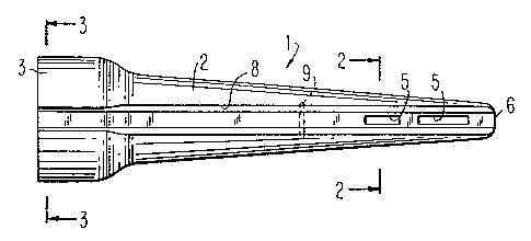
Fig. 1 is a side elevational view of the douche nozzle
of the invention:
Figs. 2 and 3 are views in section taken along lines
2-2 and 3-3, respectively, in Fig. 1:
Fig. 4 is a side elevational view of the baffle member
used in the present invention:
Figs. 5 and 6 are views in section taken along lines
5-5 and 6-6 in Fig. 4, respectively:
Fig. 7 is a side elevational view, in section, showing
the assembly of the baffle member in the nozzle
Fig. 8 is a view in section taken along lines 8-8 in
Fig. 7; and
Fig. 8A is a view similar to Fig. 8 of another
embodiment of the invention.
Referring to Fig. 1, the douche nozzle 1 is in the form
of an elongated tubular body 2 having an open proximal end 3
formed with internal threads 4 (Fig. 7) for attaching the nozzle
2

2~.~~~~~
1 to a conventional squeeze bottle (not shown). Alternatively,
the end 3 may be provided with an internal groove (not shown) for
snap fitting the nozzle 1 onto the squeeze bottle.
A plurality of slots 5 are arranged adjacent the distal
end 6 to permit liquid flowing through the passageway 7 (Fig. 7)
to exit the nozzle 1. The exterior of the tubular body 2 is
provided with four longitudinally extending recessed grooves 8,
the slots 5 being provided within the grooves 8. Grooves 8
extend from the distal end 6, across the body 2 and.across the
internally threaded proximal end or base 3.
The baffle member 10 (Fig. 4) has an elongated tubular
porous body 11 having an open proximal end or base 12 and a
closed distal end 13. Tubular porous body 11 is. preferably
tapered so as to readily fit into the tapered tubular body 2 of
nozzle 1. However, porous body 11 need not be tapered so long as
it fits within body 2. Further, body 2, while preferably
tapered, can be of uniform cross-section. If desired, the baffle
member may be contoured to the shape of nozzle 1.
Baffle. member l0 is provided with an internal
passageway 14 through which liquid may flow from the base at the
proximal end 12 to the distal end 13. Liquid escapes from
passageway 14 through the voids and channels of the porous body
11 and, to some extent, through the porous closed distal end 13.
Liquid flowing out of baffle member 10 in turn escapes from the
nozzle 1 through slots 5.
3

~~ ~~~2a
Baffle member 10 is prevented from. sliding to the right
as viewed in Fig. 7 because the distal end 13 contacts the
internal wall 2a of the distal end 6 of nozzle 1. Ribs 9 (Fig.
8) in the internal 2a wall of nozzle 1 prevent porous insert 10
from sliding to the left. Preferably, the base 12 of baffle
member 10 has the same cross-section as and sealingly contacts
inner wall 2a of the nozzle 1 so that liquid flowing through
passageway 7 cannot bypass the passageway 14 in baffle~member 10.
In this way, all of the liquid flowing through nozzle 1 must pass
through and be regulated by baffle member 10 before escaping via
slots 5.
While nozzle l is shown with a generally square cross-
section where the base 12 engages the inner wall 2a, other cross-
sections are possible. For example, Fig. 8A shows an alternative
embodiment of the invention where the baffle member 10 has a base
12a with a circular cross=section that sealingly engages the
inner wall 2a, which is likewise of circular cross-section. In
Fig. 8A the retaining rib 9a is in the form of a ring, rather
than as spaced-apart ribs.
The nozzle 1 and baffle member 10 are assembled by
sliding the member 10 through passageway 7 until base 12 passes
beyond the ribs 9. Nozzle 1 as thus assembled is used in a
conventional manner by attaching nozzle 1 to a squeeze bottle by
means of threads 4. Liquid is dispensed from the bottle in a
conventional manner by squeezing the bottle to expel the
contents. Since base 12 of member 10 sealingly engages the inner
4

wall 2a of nozzle 1, liquid flows through passageway 7 into
passageway 14, thence diffuses through the porous body 11 of
insert 10 and thence escapes in a regulated manner from nozzle 1
via slots 5.
Baffle member 10 accomplishes several purposes. Thus,
member 10 diffuses the liquid before the liquid exits the nozzle,
to ensure that the liquid exits the nozzle as gently flowing
stream, even if excessive squeezing forces are exerted on the
bottle. In the past, such excessive squeezing forces could
result in a powerful spray. Baffle member 10 also acts as a
barrier to minimize suckback of liquid into the nozzle from the
vagina when the squeezing forces on the bottle are released.
Baffle member 10 may also be used to deliver a desired
active agent along with the douching liquid. For example, member
10 may be impregnated with an active agent that is released into
the douching liquid flowing through the baffle member. Suitable
active agents may be introduced into the baffle member by
impregnating the baffle member with a solution of the active
agent followed by drying the baffle member. Alternatively, the
baffle member may be impregnated with a solution of the active
agent, the thus-impregnated member may be assembled into the
nozzle, and the assembly enclosed within a hermetically sealed
package to prevent the solution from drying out. Such techniques
are known in the art of tampons, contraceptive sponges and other
vaginal devices. See, e.g., U.S. Patents 4,186,742, 4,613,497
and 5,070,889. A wide variety of active agents may be
5

~~ ~J'3 ~~
impregnated into the baffle member, such as antibiotics, anti-
fungal agents, estrogenic steroids, progestational agents, and
the like.
It is presently preferred that the nozzle 1 be provided
with recessed grooves or channels 8 extending across the base or
proximal end 3 to the distal end 6 of nozzle f to ensure that the
douching liquid may readily drain out of the vagina.
Nozzle 1 may be made of any material suitable for
forming to the desired shape, such as polyethylene, polypropylene
l0 or the like. It is presently preferred to use transparent low-
density polyethylene to form nozzle 1, so that the consumer can
see baffle member 10.
Baffle member 10 may be made from any porous material
suitable for forming to the desired shape, such as porous plastic
foams, porous cellulosic materials and the like. It is presently
preferred to use a porous, rigid foam to form porous baffle
member 10. However, flexible, soft foams can also be used.
To ensure that baffle member 10 is sealingly engaged in
the nozzle 1, the base 12 sealingly engages inner wa11,2a of
nozzle 1. Accordingly, base l2 may be of slightly greater cross-
section as inner wall 2a, so that the base is slightly compressed
as it is forced into the nozzle 1 and beyond ribs 9. In this
manner, whether the member 10 is made from a rigid or flexible
foam, the base 12 will be urged into sealing engagement with
inner wall 2a.
6

2 ~. 3 ~ ~')
Nozzle 1 and baffle member 10 may be of any suitable
length. For example, nozzle 1 may suitably have an overall
length of about 5 inches and may suitably be provided with a
baffle member 10 of about 2 to about 2; inches. Alternatively,
nozzle 1 may have an overall length of about 3; inches and may be
provided with a baffle member of about 1 to about 1~ inches. The
selection of the length and diameter of the nozzle is not
critical. The dimensions and porosity~of the baffle member l0
will be empirically determined to provide the consumer with a
nozzle and baffle member that will permit easy and convenient
dispensing of the liquid from the squeeze bottle. The member 10
must not provide too much resistance to the flow of liquid
therethrough as to require excessive squeezing forces on the
bottle to dispense the liquid. A suitable baffle member 10 may
be a sintered, high density polyethylene foam having pore sizes
from about 5 to about 200 microns, preferably from about 80 to
about 120 microns, and a void volume greater than about 40%,
preferably from about 47 to about 53%.
7

Dessin représentatif
Une figure unique qui représente un dessin illustrant l'invention.
États administratifs

2024-08-01 : Dans le cadre de la transition vers les Brevets de nouvelle génération (BNG), la base de données sur les brevets canadiens (BDBC) contient désormais un Historique d'événement plus détaillé, qui reproduit le Journal des événements de notre nouvelle solution interne.

Veuillez noter que les événements débutant par « Inactive : » se réfèrent à des événements qui ne sont plus utilisés dans notre nouvelle solution interne.

Pour une meilleure compréhension de l'état de la demande ou brevet qui figure sur cette page, la rubrique Mise en garde , et les descriptions de Brevet , Historique d'événement , Taxes périodiques et Historique des paiements devraient être consultées.

Historique d'événement

Description Date
Le délai pour l'annulation est expiré 2014-08-12
Lettre envoyée 2013-08-12
Inactive : TME en retard traitée 2012-08-15
Lettre envoyée 2012-08-13
Lettre envoyée 2012-07-24
Inactive : Correspondance - Transfert 2012-05-10
Inactive : Lettre officielle 2012-04-04
Inactive : CIB désactivée 2011-07-27
Lettre envoyée 2010-06-22
Inactive : CIB de MCD 2006-03-11
Inactive : CIB dérivée en 1re pos. est < 2006-03-11
Accordé par délivrance 2004-10-05
Inactive : Page couverture publiée 2004-10-04
Préoctroi 2004-06-11
Inactive : Taxe finale reçue 2004-06-11
Lettre envoyée 2004-03-31
Un avis d'acceptation est envoyé 2004-03-31
Inactive : Approuvée aux fins d'acceptation (AFA) 2004-03-22
Modification reçue - modification volontaire 2004-01-20
Inactive : Dem. de l'examinateur par.30(2) Règles 2003-07-21
Inactive : Renseign. sur l'état - Complets dès date d'ent. journ. 2001-09-05
Lettre envoyée 2001-09-05
Inactive : Dem. traitée sur TS dès date d'ent. journal 2001-09-05
Toutes les exigences pour l'examen - jugée conforme 2001-08-02
Exigences pour une requête d'examen - jugée conforme 2001-08-02
Demande publiée (accessible au public) 1995-02-20

Historique d'abandonnement

Il n'y a pas d'historique d'abandonnement

Taxes périodiques

Le dernier paiement a été reçu le 2004-07-13

Avis : Si le paiement en totalité n'a pas été reçu au plus tard à la date indiquée, une taxe supplémentaire peut être imposée, soit une des taxes suivantes :

  • taxe de rétablissement ;
  • taxe pour paiement en souffrance ; ou
  • taxe additionnelle pour le renversement d'une péremption réputée.

Veuillez vous référer à la page web des taxes sur les brevets de l'OPIC pour voir tous les montants actuels des taxes.

Titulaires au dossier

Les titulaires actuels et antérieures au dossier sont affichés en ordre alphabétique.

Titulaires actuels au dossier
MEDTECH PRODUCTS, INC.
Titulaires antérieures au dossier
LAWRENCE J. STUPPI
ROBERT W. PRITCHARD
Les propriétaires antérieurs qui ne figurent pas dans la liste des « Propriétaires au dossier » apparaîtront dans d'autres documents au dossier.
Documents

Pour visionner les fichiers sélectionnés, entrer le code reCAPTCHA :


Pour visualiser une image, cliquer sur un lien dans la colonne description du document. Pour télécharger l'image (les images), cliquer l'une ou plusieurs cases à cocher dans la première colonne et ensuite cliquer sur le bouton "Télécharger sélection en format PDF (archive Zip)" ou le bouton "Télécharger sélection (en un fichier PDF fusionné)".

Liste des documents de brevet publiés et non publiés sur la BDBC .

Si vous avez des difficultés à accéder au contenu, veuillez communiquer avec le Centre de services à la clientèle au 1-866-997-1936, ou envoyer un courriel au Centre de service à la clientèle de l'OPIC.


Description du
Document 
Date
(aaaa-mm-jj) 
Nombre de pages   Taille de l'image (Ko) 
Dessin représentatif 1998-06-30 1 9
Page couverture 1995-07-15 1 109
Revendications 1995-07-15 2 161
Description 2004-01-20 3 96
Dessin représentatif 2004-03-24 1 8
Description 1995-07-15 7 206
Dessins 1995-07-15 2 32
Abrégé 1995-07-15 1 8
Page couverture 2004-08-31 1 30
Rappel - requête d'examen 2001-04-17 1 117
Accusé de réception de la requête d'examen 2001-09-05 1 194
Avis du commissaire - Demande jugée acceptable 2004-03-31 1 161
Courtoisie - Certificat d'enregistrement (document(s) connexe(s)) 2012-07-24 1 125
Avis concernant la taxe de maintien 2012-08-15 1 170
Quittance d'un paiement en retard 2012-08-15 1 163
Avis concernant la taxe de maintien 2013-09-23 1 170
Correspondance 2004-06-11 1 33
Correspondance 2010-06-03 4 268
Correspondance 2012-04-04 1 16
Taxes 1996-06-26 1 93