Sélection de la langue

Search

Sommaire du brevet 2130777 

Énoncé de désistement de responsabilité concernant l'information provenant de tiers

Une partie des informations de ce site Web a été fournie par des sources externes. Le gouvernement du Canada n'assume aucune responsabilité concernant la précision, l'actualité ou la fiabilité des informations fournies par les sources externes. Les utilisateurs qui désirent employer cette information devraient consulter directement la source des informations. Le contenu fourni par les sources externes n'est pas assujetti aux exigences sur les langues officielles, la protection des renseignements personnels et l'accessibilité.

Disponibilité de l'Abrégé et des Revendications

L'apparition de différences dans le texte et l'image des Revendications et de l'Abrégé dépend du moment auquel le document est publié. Les textes des Revendications et de l'Abrégé sont affichés :

  • lorsque la demande peut être examinée par le public;
  • lorsque le brevet est émis (délivrance).
(12) Brevet: (11) CA 2130777
(54) Titre français: JOINT MECANIQUE DE TUYAU
(54) Titre anglais: MECHANICAL PIPE JOINT
Statut: Durée expirée - au-delà du délai suivant l'octroi
Données bibliographiques
(51) Classification internationale des brevets (CIB):
  • F16L 23/024 (2006.01)
  • F16L 21/04 (2006.01)
  • F16L 21/08 (2006.01)
(72) Inventeurs :
  • HUNTER, THOMAS D. (Etats-Unis d'Amérique)
  • JACKSON, OLIN I. (Etats-Unis d'Amérique)
  • PANNELL, MINOR W. (Etats-Unis d'Amérique)
(73) Titulaires :
  • TYLER PIPE INDUSTRIES
(71) Demandeurs :
  • TYLER PIPE INDUSTRIES (Etats-Unis d'Amérique)
(74) Agent: KIRBY EADES GALE BAKER
(74) Co-agent:
(45) Délivré: 1998-09-22
(22) Date de dépôt: 1994-08-24
(41) Mise à la disponibilité du public: 1995-05-17
Requête d'examen: 1995-11-30
Licence disponible: S.O.
Cédé au domaine public: S.O.
(25) Langue des documents déposés: Anglais

Traité de coopération en matière de brevets (PCT): Non

(30) Données de priorité de la demande:
Numéro de la demande Pays / territoire Date
152,237 (Etats-Unis d'Amérique) 1993-11-16

Abrégés

Abrégé français

Cette invention concerne un joint mécanique amélioré pour l'assemblage de tuyaux à emboîtement ordinaires. Le joint comprend un fouloir dans la cavité conique de laquelle se loge une bague fendue crénelée qui comprime radialement le bout uni du tuyau et s'y accroche à mesure le fouloir est serré contre le bout évasé du tuyau adjacent. L'étanchéité est réalisée par un joint compressible placé entre la bague fendue et le bout évasé. Le fouloir comprend en outre un épaulement radiale qui s'appuie contre la bague fendue et empêche le fouloir de la dépasser à l'assemblage.


Abrégé anglais


An improved mechanical pipe joint for use in a bell
and plain pipe end assembly. The joint includes a gland
having a conical cavity for receiving a toothed split ring
that coaxially compresses and grips the plain pipe end as
the gland is tightened to the bell. The joint is sealed by
a compressible gasket positioned between the split ring and
the bell. The gland further includes an integrally formed,
radially extending shelf for abutting against the split
ring and mechanically stopping the gland from being pulled
over the split ring during joint assembly.

Revendications

Note : Les revendications sont présentées dans la langue officielle dans laquelle elles ont été soumises.


- 10 -
Claims:
1. A mechanical joint for use in a bell and plain
pipe end assembly, comprising:
a plain pipe end;
a gasket encircling the plain pipe end;
a bell including a peripheral flange and an opening
for receiving the plain pipe end, said opening further
defining a cavity for seating the gasket;
a split ring with a conical external surface; and
a gland including a peripheral flange and an opening
for encircling the plain pipe end, said opening further
having a conical shape complementing the conical external
surface of the split ring and defining a conical cavity
for seating a front edge of the split ring in a position
abutting against the gasket, said conical cavity tapering
from a front end also abutting against the gasket to a
rear end, said gland further including an integrally
formed, radially extending shelf positioned at the rear
end of the gland for abutting against a rear edge of the
split ring seated in the conical cavity when the front
end of the gland abuts against the gasket.
2. A mechanical joint for use in a bell and plain pipe
end assembly, comprising:
a plain pipe end;
a gasket encircling the plain pipe end and having a
conical external surface;

- 11 -
a bell including a peripheral flange and an opening
for receiving the plain pipe end, said opening further
having a conical shape complementing the conical external
surface of the gasket and defining a conical cavity for
seating the gasket;
a split ring encircling the plain pipe end and
having a conical external surface;
a gland including a peripheral flange and an opening
for encircling the plain pipe end, said opening further
having a conical shape complementing the conical external
surface of the split ring and defining a conical cavity
for seating the split ring, said conical cavity tapering
from a front end to a rear end, said gland further
including an integrally formed, radially extending shelf
positioned at the rear end of the gland for preventing
the split ring from becoming over-compressed during
tightening of the mechanical joint; and
wherein, when the mechanical joint is assembled and
tightened, a front edge of the split ring is positioned
abutting against the gasket, the front end of the gland
is positioned also abutting against the gasket, and the
integrally formed, radially extending shelf is positioned
abutting against a rear edge of the split ring.

Description

Note : Les descriptions sont présentées dans la langue officielle dans laquelle elles ont été soumises.

21 3~777
88880-124 PATENT
-- 1 --
IMPROVED MECHANICAL PIPE JOINT
TECHNICAL FIELD
The present invention relates to mechanical pipe
joints and, in particular, to mechanical pipe joints
including a gripping ring and a compressible gasket
positioned between the pipe bell and the gland.

21 3~7~7
BACKGROUND OF THE INVENTION
Mechanical joints for securing bell and plain pipe end
assemblies are well known in the art. One standard
mechanical joint includes a compressible gasket slipped
around the plain pipe end and positioned between the pipe
bell and the gland. Tightening of included joint securing
bolts forces the gland towards the pipe bell compressing
the gasket in a conical cavity formed in the bell and
securing the joint. The standard mechanical joint,
however, ineffectively secures the bell and plain pipe end
in instances where the pipe is internally exposed to
varying hydraulic pressures. Such pressures tend to cause
axial movement along the joint which may result in leaking
around the gasket and/or releasing of the joint.
To address the deficiencies of the standard mechanical
joint, the prior art further teaches the use of a toothed
split ring slipped around the plain pipe end and positioned
in a conical cavity formed in the gland. The tightening of
securing bolts forces the gland towards the pipe bell
compressing the gasket to seal the joint, with the conical
cavity of the gland coaxially compressing the split ring
such that the included teeth grip the plain pipe end to
secure the joint. The gripping action of the toothed split
ring secures the joint by resisting axial movement in the
joint when the pipe is exposed to varying internal
hydraulic pressures. However, over-tightening of the

,~ 3Q777
securing bolts and/or improper initial assembly alignment
may cause the split ring to become overly-compressed during
assembly resulting in a deformation of the plain pipe end
and destruction of the joint. In fact, in some instances,
the gland may be pulled completely over the split ring
during incorrect or improper assembly.

~3~7~7
SUMMARY OF THE INVENTION
The present invention is an improved mechanical pipe
joint for use in a bell and plain pipe end assembly,
comprising a gland encircling the plain pipe end having a
conical cavity for receiving a toothed split ring, the ring
having a complementary conically shaped outer surface.
Tightening of the gland to the bell causes the split ring
to coaxially compress within the conical cavity and grip
the plain pipe end. The gland further includes an
integrally formed, radially extending shelf positioned at
a narrow end of the conical cavity for abutting against an
end of the split ring. As the gland is tightened to the
bell, the shelf acts as a mechanical stop to certain
excessive movement of the gland with respect to the
coaxially compressing split ring. The shelf thus minimizes
the likelihood of an over-compression of the split ring
resulting in possible deformation of the pipe and
destruction of the joint. The joint is sealed during
tightening by a compressible gasket positioned between the
split ring and the bell and received in a conical cavity of
the bell.

777
BRIEF DESCRIPTION OF THE DRAWINGS
A more complete understanding of the improved
mechanical pipe joint of the present invention may be had
by reference to the following Detailed Description when
taken in conjunction with the accompanying Drawings
wherein:
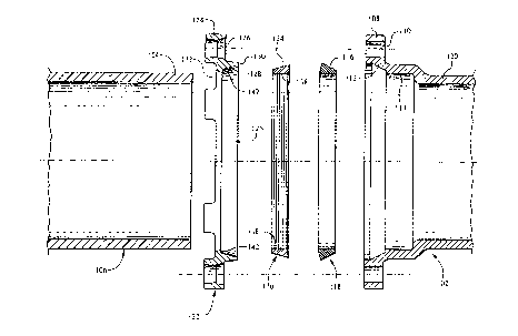
FIGURE 1 is an exploded cross-sectional view of the
improved mechanical pipe joint of the present invention;
and
FIGURE 2 is an assembled cross-sectional view of the
components of the improved mechanical pipe joint shown in
FIGURE 1.

21 ~77
DETAILED DESCRIPTION OF THE PREFERRED EMBODIMENT
Referring now to FIGURE 1, there is shown an exploded
cross-sectional view of the improved mechanical pipe joint
of the present invention for securing a conventional bell
102 to the end 104 of a conventional plain pipe 106. The
bell 102 includes a peripheral flange 108 having a
plurality of apertures 110 for receiving standard securing
bolts (not shown, see FIGURE 2) in a manner to be
described. The bell 102 further includes a conical cavity
112 narrowing in diameter from the peripheral flange 108 to
a recess portion 114 connected to a bell pipe 120 having
substantially the same diameter as the plain pipe 106. The
conical cavity 112 of the bell 102 is shaped to complement
the outer conically shaped surface 116 of a compressible
gasket 118. The diameter of the bell 102 at the recess
portion 114 is selected to receive the plain pipe end 104
in a manner to be described.
The mechanical joint further includes a gland 122 with
a peripheral flange 124 having an opening 125 for
encircling the plain pipe 106 and a plurality of peripheral
apertures 126 equal in number and capable of alignment with
the apertures 110 of the bell 102. The gland 122 further
includes a conical cavity 128 associated with the opening
125 narrowing in diameter from a forward end 130 to a
rearward end 132 of the gland. The conical cavity 128 of
the gland 122 is shaped to complement the outer conically

2 ~ 3 ~ ~ 7 j~ -i
shaped surface 134 of a split ring 136. The split ring 136
includes a plurality of circumferential teeth 138 on an
inner cylindrical surface thereof, and also includes a well
known gap or split (not shown) for facilitating a coaxial
~ / 5 compression of split ring within the conical cavity 128 and
gripping of the plain pipe end 104 with joint assembly.
The gland 122 further includes a radially extending and
integrally formed shelf 142 positioned adjacent the
rearward end 132 for abutting against the narrow end of the
split ring 136 when the split ring is seated in the conical
cavity 128.
With reference now to FIGURES 1 and 2, assembly of the
joint of the present invention will be described. The
gland 122 is first slipped onto the end 104 of the plain
pipe 106 with the forward end 130 of the gland facing the
plain pipe end. The split ring 136 is then slipped onto
the plain pipe end 104 with its narrow end facing the gland
122 for subsequent insertion into the conical cavity 128.
The compressible gasket 118 is then slipped onto the plain
pipe 106 and positioned a predetermined distance away from
the plain pipe end 104. The pipe 106 is then inserted into
the recess portion 114 of the bell 102 with the conical
cavity 112 of the bell 102 receiving the positioned gasket
118. The split ring 136 is then pushed against the gasket
118 and the gland 122 is pushed against the split ring such
that the ring is received in the conical cavity 128.

~ 3 n 77 7
-8-
Standard securing bolts 140 are then inserted through the
aligned apertures 110 and 126 of the bell 102 and gland
122, respectively, and tightened to draw the gland toward
the bell. As the joint is tightened, the split ring 136 is
coaxially compressed within the conical cavity 128 of the
gland 122, with the circumferential teeth 138 engaging the
outer surface of the plain pipe 106 to resist subsequent
axial pipe movement. In this connection, the radial shelf
142 abuts against the split ring 136 and functions as a
mechanical stop to certain excessive movement of the gland
122 with respect to the split ring. In particular, the
self 142 resists the excessive movement of the gland 122
over the split ring 136 which is likely to cause over-
compression of the split ring. The shelf 142 thus
functions to save the plain pipe end 104 from deformation
and the joint from destruction resulting from ring 136
over-compression. Furthermore, the radial shelf 142 abuts
against the narrow end of the split ring 136 pushing the
split ring against the gasket 118, and compressing the
gasket into the conical cavity 112 of the bell 102 to seal
the joint. At the same time, the forward end 130 of the
gland 122 is placed in contact with and compresses the
gasket 118 further sealing the joint.
Although a preferred embodiment of the improved
mechanical joint of the present invention has been
illustrated in the accompanying Drawings and described in
the foregoing Detailed Description, it will be understood
that the invention is not limited to the embodiment

~ 1 3~i7~7
disclosed, but may be modified without departing from the
spirit of the invention as set forth and defined by the
following claims.

Dessin représentatif
Une figure unique qui représente un dessin illustrant l'invention.
États administratifs

2024-08-01 : Dans le cadre de la transition vers les Brevets de nouvelle génération (BNG), la base de données sur les brevets canadiens (BDBC) contient désormais un Historique d'événement plus détaillé, qui reproduit le Journal des événements de notre nouvelle solution interne.

Veuillez noter que les événements débutant par « Inactive : » se réfèrent à des événements qui ne sont plus utilisés dans notre nouvelle solution interne.

Pour une meilleure compréhension de l'état de la demande ou brevet qui figure sur cette page, la rubrique Mise en garde , et les descriptions de Brevet , Historique d'événement , Taxes périodiques et Historique des paiements devraient être consultées.

Historique d'événement

Description Date
Inactive : Périmé (brevet - nouvelle loi) 2014-08-24
Inactive : CIB de MCD 2006-03-11
Inactive : TME en retard traitée 2005-09-01
Lettre envoyée 2005-08-24
Lettre envoyée 2004-12-01
Lettre envoyée 2001-09-07
Accordé par délivrance 1998-09-22
Préoctroi 1998-04-14
Inactive : Taxe finale reçue 1998-04-14
Lettre envoyée 1997-10-15
Un avis d'acceptation est envoyé 1997-10-15
Inactive : Renseign. sur l'état - Complets dès date d'ent. journ. 1997-10-09
Inactive : Dem. traitée sur TS dès date d'ent. journal 1997-10-09
Inactive : CIB enlevée 1997-08-22
Inactive : CIB en 1re position 1997-08-22
Inactive : CIB attribuée 1997-08-22
Inactive : Approuvée aux fins d'acceptation (AFA) 1997-08-13
Toutes les exigences pour l'examen - jugée conforme 1995-11-30
Exigences pour une requête d'examen - jugée conforme 1995-11-30
Demande publiée (accessible au public) 1995-05-17

Historique d'abandonnement

Il n'y a pas d'historique d'abandonnement

Taxes périodiques

Le dernier paiement a été reçu le 1998-08-17

Avis : Si le paiement en totalité n'a pas été reçu au plus tard à la date indiquée, une taxe supplémentaire peut être imposée, soit une des taxes suivantes :

  • taxe de rétablissement ;
  • taxe pour paiement en souffrance ; ou
  • taxe additionnelle pour le renversement d'une péremption réputée.

Les taxes sur les brevets sont ajustées au 1er janvier de chaque année. Les montants ci-dessus sont les montants actuels s'ils sont reçus au plus tard le 31 décembre de l'année en cours.
Veuillez vous référer à la page web des taxes sur les brevets de l'OPIC pour voir tous les montants actuels des taxes.

Titulaires au dossier

Les titulaires actuels et antérieures au dossier sont affichés en ordre alphabétique.

Titulaires actuels au dossier
TYLER PIPE INDUSTRIES
Titulaires antérieures au dossier
MINOR W. PANNELL
OLIN I. JACKSON
THOMAS D. HUNTER
Les propriétaires antérieurs qui ne figurent pas dans la liste des « Propriétaires au dossier » apparaîtront dans d'autres documents au dossier.
Documents

Pour visionner les fichiers sélectionnés, entrer le code reCAPTCHA :


Pour visualiser une image, cliquer sur un lien dans la colonne description du document. Pour télécharger l'image (les images), cliquer l'une ou plusieurs cases à cocher dans la première colonne et ensuite cliquer sur le bouton "Télécharger sélection en format PDF (archive Zip)" ou le bouton "Télécharger sélection (en un fichier PDF fusionné)".

Liste des documents de brevet publiés et non publiés sur la BDBC .

Si vous avez des difficultés à accéder au contenu, veuillez communiquer avec le Centre de services à la clientèle au 1-866-997-1936, ou envoyer un courriel au Centre de service à la clientèle de l'OPIC.


Description du
Document 
Date
(aaaa-mm-jj) 
Nombre de pages   Taille de l'image (Ko) 
Description 1997-07-15 9 213
Revendications 1997-07-15 2 66
Dessins 1997-07-15 2 51
Description 1995-10-27 9 545
Revendications 1995-10-27 2 139
Abrégé 1995-10-27 1 96
Dessins 1995-10-27 2 129
Dessin représentatif 1998-08-31 1 15
Avis du commissaire - Demande jugée acceptable 1997-10-14 1 165
Avis concernant la taxe de maintien 2005-09-12 1 172
Quittance d'un paiement en retard 2005-09-12 1 165
Correspondance 2001-09-06 4 112
Correspondance 1998-04-13 1 41
Correspondance 2004-11-30 1 16
Taxes 1996-08-11 1 63
Correspondance de la poursuite 1994-08-23 8 267
Correspondance de la poursuite 1994-11-20 1 53
Correspondance de la poursuite 1997-06-15 1 38
Correspondance de la poursuite 1995-11-29 2 54
Courtoisie - Lettre du bureau 1996-01-03 1 49