Note : Les descriptions sont présentées dans la langue officielle dans laquelle elles ont été soumises.
~ 2131343
MODULAR CONV~:YOK TRACR CONN~!CTION
Background of the Invention
This invention relates to improvements in the
installation and joining of end-to-end track sections of
industrial conveyor systems employing track sections of low
tolerance construction and, in particular, to a modular track
configuration employing end connections which ensure proper
alignment of the running surfaces of the end-to-end sections.
Conventional power and free conveyor systems utilize a
track formed by end-to-end straight, curved, dip and special
track sections that are typically joined by flange couplings at
their abutting ends which must be welded together to form a
permanent joint. In an overhead power and free conveyor, for
example, the power track is provided by a steel I-beam mounted
above and coextensive with a pair of opposed channel iron
members. The I-beam, often referred to as the power rail,
supports the drive trolleys and drive chain with the opposed
channel members forming a track which supports the free trolleys
and associated load-bearing carrier assemblies. In a typical
installation these track sections are suspended from overlying
main beams of the superstructure of the building in which the
conveyor is installed as, for example, disclosed in U. S. patent
No. 4,635,558.
Both the I-beams and the channel members providing the
power track and the free track, respectively, are formed from hot
rolled steel with manufacturing tolerances on the order of +/-
1/8 inch. Accordingly, it is often difficult to precisely align
~131343
_ -2
the running surfaces of the track sections at a joint and, once
alignment is achieved, hold the sections in proper alignment.
As a result, the conventional installation techni~ue employs
coupling flanges at the joints which are initially bolted
together to hold the track members once they are aligned,
followed by welding the coupling flanges together to preclude
movement (and attendant misalignment) that could otherwise occur
due to vibration of the tracks during operation of the conveyor
system. Therefore, installation heretofore has been very labor
intensive due to the need to adjust for misalignment caused by
wide manufacturing tolerances and the expense of welding the
bolted flanges at the track joints.
summarY of the Invention
It is, therefore, the primary object of the present
invention to provide a track connection for the track sections of
conveyor systems which ensures alignment of the running surfaces
of the track and provides a secure, weldless connection.
As a corollary to the foregoing object, it is an
important aim of this invention to enable modular track
construction in industrial conveyor systems by providing track
sections with compatible end connections.
Another important object of this invention is to
provide the ends of such track sections with an alignment device
which, in installing the track sections, will automatically
establish correct alignment of the running surfaces of the end-
to-end sections so that variation in track section configuration,
21~13~3
-3
caused by low manufacturing tolerances, will not create an
irregularity in the running surface.
Still another important object of this invention is to
provide an alignment device as aforesaid located closely adjacent
the running surfaces of the track sections so that movement of
the running surfaces to a misaligned condition is precluded
without the need to weld the track sections together.
Yet another important object of the invention is to
provide such an alignment device in cooperation with a flange
coupling at the abutting ends of the track sections to secure the
track sections in end-to-end relationship without the need to
weld the coupling flanges together.
Furthermore, it is an important object of this
invention to provide such an alignment device that employs
tubular elements on respective abutting ends which, when brought
into axial registration, establish correct alignment of the
running surfaces, such alignment being maintained by insertion of
a pin through the elements to unite the same in register.
Additionally, particularly in power and free conveyor
systems, it is an object of this invention to locate the
alignment elements out of interference with a moving trolley but
closely adjacent to the internal running surfaces presented by
the rail flanges of the I-beam and channel member tracks of the
system, such as on the lower surface of the I-beam flange or the
proximal end of the channel flange.
-3(a)-
In a broad aspect, then, the present invention relates
to a conveyor system, in which is provided a pair of end-to-
end track sections presenting abutting ends, each of said
S sections having a rail flange presenting an upwardly facing,
internal running surface for a moveable component of the
conveyor system and an adjacent external surface out of
running contact with said component, an alignment element
rigidly affixed on the abutting end of each of said sections
respectively; said elements being located on the external
surfaces of respective flanges at predetermined relative
positions and having means establishing correct alignment of
the running surfaces of the sections when the elements are
united in register with each other; a mating connector
engaging said elements at said relative positions thereof to
unite the elements in register and hold the running surfaces
in correct alignment; and coupling means interconnecting
said sections at said abutting ends to secure the sections
in end-to-end relationship with said united elements
maintaining said alignment of the running surfaces.
In another broad aspect, the present invention relates
to a power and free conveyor system, in which is provided a
power track for carrying power trolleys of the conveyor
system; a free track for carrying free trolleys of the
conveyor system; structure securing said power and free
tracks in vertically spaced relationship; said tracks
- 3(b) -
including end-to-end track sections presenting abutting
ends, each of said sections having a rail flange presenting
an upwardly facing, internal running surface for a trolley
of the conveyor system and an adjacent external surface out
of running contact with said trolley; alignment elements
rigidly affixed to the abutting ends of said track sections;
said elements being located on the external surfaces of said
flanges at predetermined relative positions and having means
establishing correct alignment of the running surfaces of
the track sections when each pair of said elements on the
abutting ends of adjacent sections is united in register;
mating connectors engaging corresponding pairs of said
elements at said relative positions thereof to unit the
elements in register and hold the respective running
surfaces in correct alignment; and coupling means
interconnecting said track sections at said abutting ends
thereof to secure the sections in end-to-end relationship
with said united elements maintaining said alignment of the
running surfaces.
-4- ~131343
Other objects will become apparent as the detailed
description proceeds.
Brief Description of the Drawings
Fig. 1 is a perspective view of a portion of a track
section of a power and free conveyor system, showing the end of
the section in the foreground prior to connection with an
adjacent track section.
Fig. 2 is a perspective view of the track section shown
in Fig. 1, looking at the end of the section seen in the
foreground in Fig. 1 and revealing the alignment bushings and
coupling flanges.
Fig. 3 is an enlarged, exploded, detail view showing
two alignment bushings in register and illustrating the pin that
unites the bushings.
Fig. 4 is a fragmentary, exploded, perspective view
showing the abutting ends of track sections that are to be
joined.
Fig. 5 is a fragmentary, elevational view of the
interconnected track sections on a reduced scale and illustrates
a power and free conveyor thereon.
Fig. 6 is a detail at the joint circumscribed by the
broken line circle in Fig. 5.
~ ~1313~3
Detailed Description
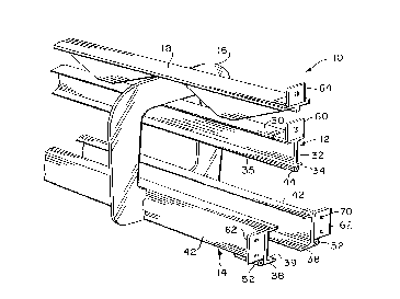
Fig. 1 shows a portion of a track section 10 of an
overhead power and free conveyor, section 10 and a second track
section 10' (Figs. 4 and 5) having a configuration known in the
art and described in detail in the aforesaid patent
No. 4,635,558. Track sections 10, 10' are representative of long
span sections of uniform length (approximately 30 feet or 9
meters) that are joined in end-to-end relationship to provide the
power and free tracks of a particular conveyor system.
The conventional components of track section 10, it
being understood that section 10' is identical thereto, comprise
an I-beam power rail 12, a free trolley track 14, a yoke plate 16
suspending the free track 14 below the power rail 12, and a
reenforcing rail cap 18 of the type disclosed in patent
No. 4,635,558. It will be understood that the views herein are
fragmentary and that, therefore, there are a plurality of yoke
plates 16 spaced longitudinally along each track section.
The power rail 12 provides a track for the power
trolleys 20 (Fig. 5) of the conveyor system, trolleys 20 carrying
a conveyor chain 22 from which pusher dogs 24 depend for
engagement with free trolleys 26 on the free track 14 in the
usual manner. Fig. 5 illustrates a load-bearing carrier bar 28
extending from the front trolley 26 to the rear free trolley 26
shown.
The I-beam power rail 12 has an upper flange 30, a
vertical web 32 and a lower flange 34, the latter providing a
~131343
--6--
horizontally projecting rail flange presenting upper surfaces 35
on both sides of web 32 upon which rollers 36 (Fig. 5) of the
power trolleys 20 run. Similarly, a pair of spaced, lower
horizontal flanges 38 of the free track 14 present running
surfaces 39 for the wheels 40 (Fig. 5) of free trolleys 26.
Flanges 38 are the lower flanges of a pair of confrontingly
aligned channel members 42 that comprise the free track 14.
When the track sections 10, 10' are joined in end-to-
end relationship to form a continuous piece of track, the
connections at the abutting ends of adjacent sections must both
rigidly interconnect the sections and maintain the running
surfaces 35, 35' and 39, 39' in correct, coplanar alignment. Any
misalignment causes an irregularity or bump which will be
encountered by the trolleys as they traverse a misaligned joint.
Proper alignment is ensured in the present invention by the use
of alignment elements and mating connectors as will be described,
in conjunction with coupling members that are bolted together to
form a weldless connection.
Pursuant to the teachings of the present invention, a
tubular bushing 44 is located on the downwardly facing, external
surface 46 of the lower flange 34 of I-beam 12 and is welded in
place at the center of the flange directly beneath the web 32.
The bushing 44 has an axial opening 48 therethrough (Fig. 3)
which extends in longitudinal alignment with the track section.
Likewise, track section 10' has an identical bushing 44' at the
abutting end of its I-beam 12', both of such bushings receiving a
-7- ~31343
spring pin 50 when the bushings 44, 44' are in register with each
other and the track ends are brought into engagement. This
condition is illustrated in Fig. 6 where it may be seen that the
pin 50 has been partially inserted.
In similar fashion, a pair of tubular bushings 52 are
located on respective external surfaces 54 of channel members 42
at the proximal ends of flanges 38 as best seen in Fig. 2. These
bushings 52 are also welded in place with their axes in
parallelism and aligned with the longitudinal run of the track
section. At the joint illustrated herein, bushings 52 are united
with corresponding bushings 52' on track section 10' by spring
pins 56 in the same manner as described above for bushings 44,
44'. Bushings 44 and 52, and pins 50 and 56 are identical except
for sizing as illustrated, and are also provided at the opposite
ends of sections 10, 10' not shown in the drawings.
It should be understood that special attention is given
to the placement of bushings 44, 52 during fabrication of the
track sections. As discussed hereinabove, the I-beams 12 and
channel members 42 may vary significantly in cross-sectional
dimension due to low manufacturing tolerances. Therefore, each
bushing 44, 52 is located on an individual track member at the
same position relative to the running surface 35 or 39 so that
any pair of fabricated track sections, when brought into end-to-
end relationship, will be in proper alignment when the pairs of
alignment bushings are in register.
~ 2131~43
--8--
Additionally, an angle member 60 is welded to the upper
flange 30 of I-beam 12 at the end thereof, it being understood
that an identical angle member is likewise welded at the opposite
end of track section 10 not shown in the drawings. A pair of
angle members 62 are welded to the respective channel members 42
just above the bushings 52, and an angle member 64 is welded to
the end of the rail cap 18. These angle members present coupling
flanges which are bolted together in the usual manner as
illustrated by the bolt/nut combinations 66 seen in Fig. 6
interconnecting an abutting pair of members 62, 62'.
The present invention provides a modular track
configuration in view of the end connections employed. Each of
the track sections 10, 10', etc. is interchangeable in assembly
since all of the end connections are compatible. Once two track
sections, such as 10 and 10' illustrated herein, are brought into
end-to-end relationship, insertion of the pins 50 and 56 into the
axially aligned bushings 44-44' and 52-52' automatically ensures
that the running surfaces 35, 35' and 39, 3g' will likewise be in
proper alignment. By locating the bushings on external surfaces
46 and 54 that are closely adjacent to the running surfaces, but
out of running contact with the trolleys, the running surfaces
are effectively held and resist any tendency to shift to a
misaligned condition.
Once the pins 50, 56 are in place, the bolts 62 that
interconnect the coupling flanges 60, 62 and 64 may be tightened
and the connection is complete. It should be understood that the
2131~43
g
bolt holes (such as seen at 70 in Fig. 2) are purposely enlarged
relative to the bolts so as to allow for proper positioning of
the aligned bushings and insertion of the pins before the bolts
are tightened to provide a permanent joint.